

Dimplex LVA231, LVA232 Operating And Maintenance Instructions Manual
08/35168/3 Issue 3
Model: LVA231
Model: LVA232
UK DE FR ES IT RUNL
The product complies with the European Safety Standards EN60335-2-30 and the European Standard Electromagnetic Compatibility (EMC)
EN55014, EN60555-2 and EN60555-3 These cover the essential requirements of EEC Directives 2006/95/EC and 2004/108/EC
2
3
1
1
2
3
500
235
* 959 - 1209
173
209
905
65
495
* 750 - 1000
‘a’
750
65
750
* 620 - 870
LVA 231
LVA 232
‘a’
A
B
‘x’
‘y’
1
2
3
4
‘a’
‘b’
x
y
z
x
y
z
x
B
A
C
7
5
4
6
Fig. 6
‘X’
‘Y’


UK ................................................. 1
DE ................................................. 3
NL ................................................. 5
FR ................................................. 7
ES ................................................. 9
IT ................................................. 11
RU ................................................. 13
Living Art Range
Model(s): LVA231 & LVA232
IMPORTANT: THESE INSTRUCTIONS SHOULD BE READ CAREFULLY AND RETAINED FOR FUTURE REFERENCE
Important Safety Advice
When using electrical appliances, basic precautions should
be followed to reduce the risk of fire, electric shock, and injury
to persons, including the following:
If the appliance is damaged, check immediately with the
supplier before installation and operation.
Do not use this appliance in the immediate surroundings of a
bath, shower or swimming pool.
Do not use outdoors.
WARNING: With the heat ‘On’ (indicated by red LED - see ‘y’
in detail A in Fig. 1) areas to the left and right of the glass
screen will become hot. However momentary contact with any
part of it should not cause injury.
WARNING: DO NOT OBSTRUCT AIR VENTS AT THE TOP AND
BOTTOM OF THE APPLIANCE AS CONSEQUENT
OVERHEATING CAN CAUSE DAMAGE
In the event of a fault switch off the appliance.
Switch off the appliance when not required for long periods.
This appliance is not intended for use by children or other
persons without assistance or supervision if their physical,
sensory or mental capabilities prevent them from using it
safely. Children should be supervised to ensure that they do
not play with the appliance.
If the supply cord is damaged it must be replaced by the
manufacturer or service agent or similarly qualified person
in order to avoid a hazard.
Electrical
WARNING – THIS APPLIANCE MUST BE EARTHED
This appliance must be used on an AC ~ supply only and the voltage
marked on the appliance must correspond to the supply voltage.
Do not switch the appliance on until properly installed. Please read
all the safety warnings and operating instructions.
General
Unpack the appliance carefully and retain the packaging for possible
future use, in the event of moving or returning the appliance to your
supplier.
Contents of Carton
• Living Art Range Model
• Wall fixing plate (attached to chassis for transit)
• Fixing screws and wall plugs
• Remote control and batteries (AAA type)
• Cable and plug
The appliance can be operated remotely or manually - see ‘Operation’.
General features of the remote control are:
• Selection of 8 different scenes.
• Sound effects relevant to your selected scene may be
activated and the volume increased or decreased.
• Switch off to Standby indicated by red LED on left - see ‘x’ in
detail A in Fig. 1.
• Heat On/Off red LED on right indicates heat ‘On’ - see ‘y’ in
detail A in Fig. 1.
Installation
Do not connect appliance until properly fixed to the wall and the
Instruction leaflet is read fully.
For installation of the appliance, care must be taken not to damage
any cables that may be concealed in the wall.
Please be careful while drilling the holes.
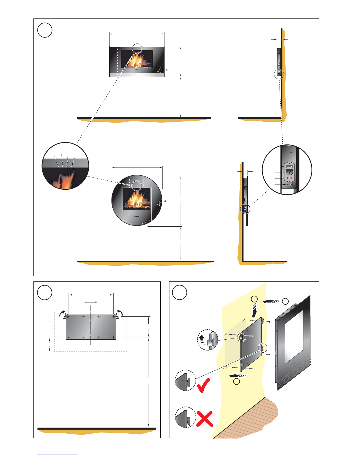
These models are designed to be permanently wall mounted - see
Fig. 1 for recommended fixing dimensions from floor to underside of
the appliance for optimum viewing of the display screen. The outline
of the chassis and the position of the electrical socket are shown as
dotted outlines in Fig. 1. Any dimensions indicated
‘*’
are recommended
dimensions.
The wall plate is secured to the chassis with 2 screws (see detail view
‘X’ in Fig. 4). To wall mount the appliance first remove the wall plate
from the chassis by removing the two screws and rotating the corner
hinges away from the chassis.
Note : Retain the two screws for future use.
Fix the wall plate to the wall using the wall plugs and screws provided.
(Note: Ensure that the wall is suitable for the screws & plugs provided).
Use the wall plate as a template to mark the hole positions for drilling
- see Fig. 2. Drill and fix the wall plate in position with one screw
initially to check the plate is level before marking and drilling the
remaining holes - see ‘1’ in Fig. 3. Ensure the wall plate is fitted the
correct way up i.e. the side hooks are pointed upwards - see Fig. 3.
The appliance can then be fitted to the wall plate by aligning the slots
on the chassis with the side hooks on the wall plate. This is best
achieved by positioning the appliance vertically above the plate (see ‘2’
in Fig. 3) and locating on the side hooks and sliding the chassis
downwards (see ‘3’ in Fig. 3).
The corner hinges on the wall plate may be used to secure the
appliance against inadvertent dislodgement. Simply rotate the hinges
upwards (see Fig. 2 and detail view in Fig. 3) to a position above the
chassis. They can then be screw fixed using the screws removed earlier
(see detail view ‘X’ in Fig. 4 of corner hinge rotated up and screw fixed
in position).
NOTE: The appliance should be ‘HARD’ wired to a fused switched
spur located behind the glass screen so as to be hidden from view see ‘a‘ in Fig. 1. The cable should be shortened as necessary in order
to remain concealed behind the glass display screen.
Please consult a qualified electrician for appropriate wiring requirements.
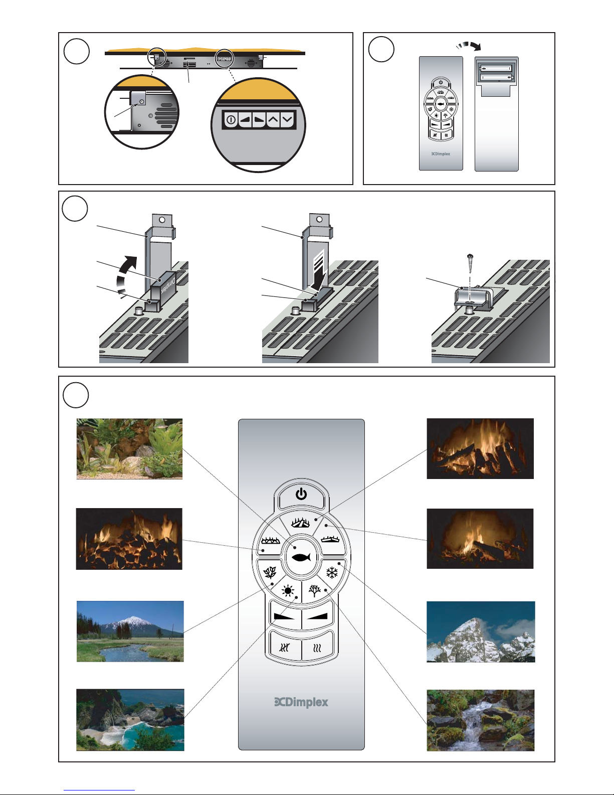
Operation
Plug in the connector from the electrical hard wiring outlet to the
appliance (see ‘2’ in detail B Fig. 1).
The illuminated power ‘On’ switch (see ‘3’ in detail B Fig. 1) must first
be switched ‘On’ to operate the appliance either manually or by remote
control.
The ‘Coal’ scene will automatically come on when the power ‘On’ switch
is switched on.
Switch the heat ‘On’ if required (see ‘4’ in detail B Fig. 1). Heat ‘On’
will be indicated by a red LED (see ‘Y’ in detail ‘A’ Fig. 1).
Note: The temperature of the glass will rise steadily up to a maximum
of approximately 60 degrees C when the heat is turned ‘on’.
The Memory Card (see ‘y’ in Fig. 6) as fitted is held in position by a
hinged cover (see ‘x’ in Fig. 6) which is screwed in place to provide
protection against damage in handling and for added security - see C
in Fig. 6.
If required the card can be removed by unscrewing and hinging back
the cover - see A in Fig. 6, and simply pressing down on the button
(see ‘z’ in Fig. 6) beside the card to eject it.
In replacing the card it should drop down into position before pressing
home – see B in Fig. 6 (force should not be used in fitting the card as
damage can result). Ensure the logo on the card is facing down when
inserting it, as shown in A in Fig. 6.
Important: Always switch off the appliance before removing the
card.
Failure to do so will result in a picture freeze. To restart, the appliance
must first be turned off at the illuminated power ‘On’ switch - see ‘3’ in
detail B in Fig. 1 and the card pressed into position, and then the
illuminated power ‘On’ switch turned on again.
UK
- 1 -
Manual Control Operation
The manual controls are located on top of the appliance behind the
glass screen (see detail view ‘Y’ in Fig. 4).
For description of manual button settings see below:
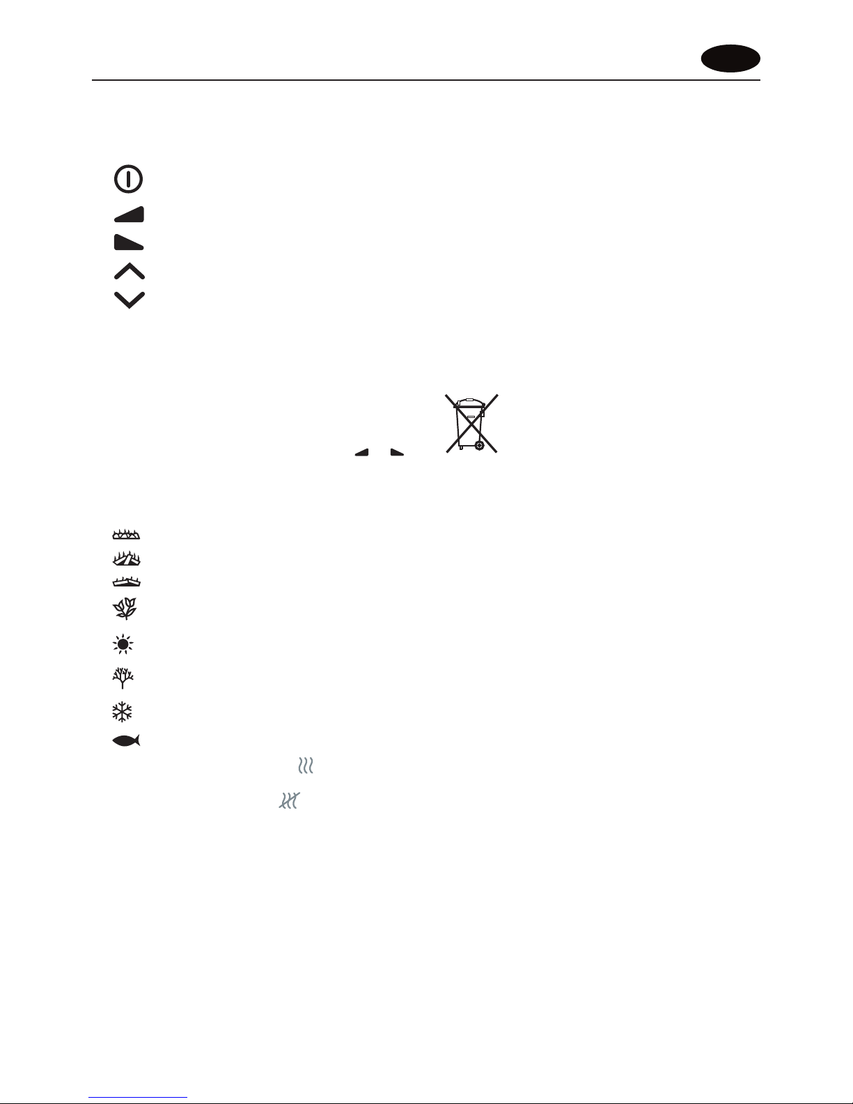
Standby Switch ‘On’ / ‘Off’
Audio volume ‘Down’
Audio volume ‘Up’
Scene selection ‘Up’
Scene selection ‘Down’
The manual Heat On/Off switch is located at the lower right side of the
appliance on Model LVA231 and at the lower left hand side of Model
LVA232 (see ‘4’ in detail B in Fig. 1).
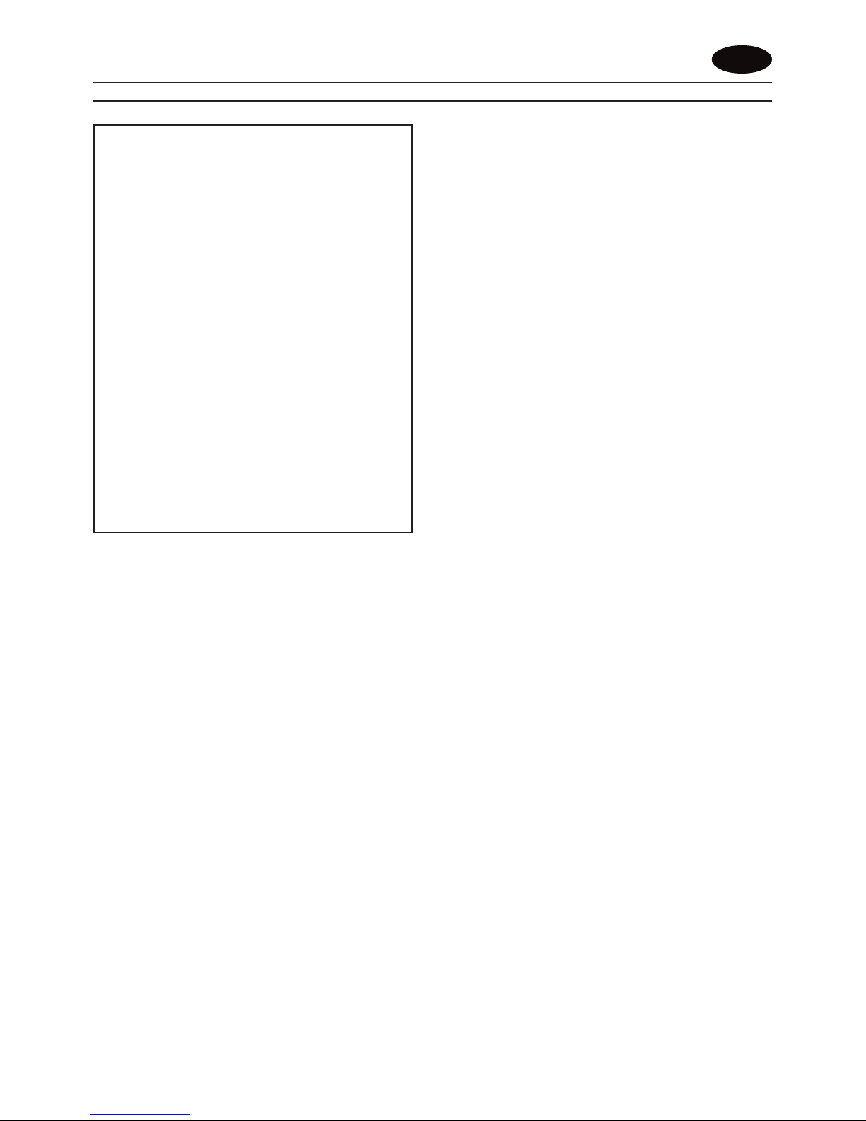
Remote Control Operation
The remote control may be operated once the appliance is switched
‘ON’. Select any one of eight scenes on your remote control - see
Fig. 7.
Each scene has it’s own particular sound effect which may be activated
and adjusted by pressing the audio volume control buttons ( and )
to the level required, while aiming the remote control at the IR sensors
(see ‘a’ and ‘b’ in detail A in Fig. 1).
See below for button settings on remote control for various scene
selections:
‘Coal’ Fire scene
‘Log’ Fire scene
‘Embers’ Fire scene
‘Spring’ scene
‘Summer’ scene
‘Autumn’ scene
‘Winter’ scene
‘Aquarium’ scene
The heat may be switched On by pressing button Heat ‘On’ is
indicated by red LED (see ‘y’ in detail A in Fig. 1).
The heat may be turned Off by pressing button.
The appliance may be switched into Standby mode by pressing the
Standby On/Off button (see ‘x’ in detail A in Fig. 1). Switching the
appliance back On using the Standby button will return to the scene
that was on the screen before turning it off. Alternatively any scene
selected may be switched on.
Note: When the appliance is switched into Standby mode the heat will
automatically be turned off, and if required when the appliance is
switched On again it must be independently switched on remotely or
manually as outlined in ‘Operation’.
Note: The user may notice a slight frame freeze lasting less than
0.5 seconds after a scene has run for approximately 5 minutes.
This is normal and should not be a cause for concern.
The user has an option of turning heat On in Standby mode without
having a scene selected.
Remote Control Assembly
Note: The remote control is packed separately in the carton.
1. Slide open the battery cover on the back of the remote
transmitter.
2. Install the AAA batteries into the remote control (see Fig. 5).
3. Replace battery cover.
Discard Leaking Batteries
Dispose of batteries in the proper manner according to Provincial and
local regulations. Any battery may leak electrolyte if mixed with a
different battery type, if inserted incorrectly, if all the batteries are not
replaced at the same time, if disposed of in a fire or if an attempt is
made to charge a battery not intended to be recharged.
Cleaning
WARNING – ALWAYS DISCONNECT FROM THE POWER SUPPLY
BEFORE CLEANING THE APPLIANCE.
For general cleaning use a soft clean duster – never use abrasive
cleaners. The glass viewing screen should be cleaned carefully with a
soft cloth. DO NOT use proprietary glass cleaners.
Recycling
For electrical products sold within the European Community.
At the end of the electrical product’s useful life it should
not be disposed of with household waste. Please recycle
where facilities exist. Check with your Local Authority or
retailer for recycling advice in your country.
After Sales Service
Should you require after sales service or should you need to purchase
any spares, please contact the retailer from whom the appliance was
purchased or contact the service number relevant to your country on
the warranty card.
Please do not return a faulty product to us in the first instance as this
may result in loss or damage and delay in providing you with a
satisfactory service.
Please retain your receipt as proof of purchase.
UK
- 2 -
Living Art Range
Modell(e): LVA231 & LVA232
WICHTIG: DIESE ANWEISUNGEN SORGFÄLTIG LESEN UND FÜR SPÄTERE REFERENZ AUFBEWAHREN
Wichtige Sicherheitshinweise
Beim Gebrauch von elektrischen Geräten sollten
grundlegende Sicherheitsmaßnahmen befolgt werden,
um das Risiko von Brandbildung, elektrischem Schock
und Verletzungen zu minimieren. Das schließt Folgendes
ein:
Wenn das Gerät beschädigt ist, umgehend die
Lieferfirma kontaktieren, bevor die Montage und
Inbetriebnahme des Geräts vorgenommen wird.
Dieses Gerät nicht in unmittelbarer Nähe von Bädern,
Duschen oder Schwimmbädern verwenden.
Nicht im Freien verwenden.
WARNUNG: Bei ‘Eingeschalteter’ Wärme (die rote LED - siehe
‘y’ in Detail A in Abb. 1 - brennt) werden die Bereiche links
und rechts neben der Glasscheide heiß. Eine sehr kurze
Berührung dieser Flächen führt in Normalfall jedoch nicht
zu Verbrennungen.
WARNUNG: DIE LÜFTUNGSÖFFNUNGEN OBEN UND UNTEN IM
GERÄTEGEHÄUSE NICHT ZUDECKEN ODER ZUSTELLEN;
SONST KANN ES ZU ÜBERHITZUNG UND SCHÄDEN AM GERÄT
KOMMEN
Bei einem Fehler das Gerät ausschalten.
Das Gerät auch ausschalten, wenn es für längere Zeit
nicht verwendet wird.
Dieses Gerät darf von Kindern oder anderen Personen
nicht unbeaufsichtigt bzw. ohne Hilfestellung verwendet
werden, wenn diese körperlich oder psychisch nicht in
der Lage sind, das Gerät gefahrlos zu benutzen. Kinder
müssen beaufsichtigt werden um sicherzustellen, dass
sie nicht mit dem Gerät spielen.
Wenn das Stromversorgungskabel beschädigt ist, muss
es durch den Hersteller bzw. einen
Kundendienstmitarbeiter oder eine entsprechend
qualifizierte Fachkraft ausgetauscht werden, um ein
Sicherheitsrisiko zu vermeiden.
Elektrik
WARNUNG - DIESES GERÄT MUSS GEERDET WERDEN
Dieses Gerät darf nur mit Wechselstrom betrieben werden, und die
am Gerät angegebene Spannung muss der eingespeisten Spannung
entsprechen.
Das Gerät darf nicht eingeschaltet werden, bevor es
ordnungsgemäß installiert ist. Bitte alle Sicherheitshinweise und
Betriebsanweisungen beachten.
Allgemeine Hinweise
Das Gerät vorsichtig auspacken und die Verpackung für zukünftige
Verwendungszwecke aufbewahren, z. B. im Falle eines Umzugs
oder falls das Gerät an die Lieferfirma zurückgeschickt werden
muss.
Inhalt des Lieferkartons
• Living Art Range Modell
• Platte zur Wandbefestigung (für den Transport am Gehäuse
befestigt)
• Befestigungsschrauben und Wanddübel
• Fernbedienung und Batterien (Typ AAA)
• Kabel mit Stecker
Das Gerät kann manuell oder über die Fernbedienung bedient werden
- siehe ‚Betrieb’.
Allgemeine Funktionen der Fernbedienung:
• Anwahl von 8 verschiedenen Szenen.
• Zur gewählten Szene gehörende Soundeffekte können
aktiviert und die Lautstärke angehoben oder abgesenkt
werden.
• Umschalten auf Standby-Betrieb, wird durch die rote LED
auf der linken Seite angezeigt - siehe ‘x’ in Detail A in Abb. 1.
• Wärme Ein/Aus rote LED auf der rechten Seite zeigt Wärme
‘Ein’ an - siehe ‘y’ in Detail A in Abb. 1.
Montageort
Das Gerät nicht an die Stromversorgung anschließen, bevor es
ordnungsgemäß an der Wand montiert ist, und die
Bedienungsanleitung vollständig gelesen wurde.
Bei der Montage des Geräts darauf achten, dass in der Wand verlegte
Kabel nicht beschädigt werden.
Vorsicht beim Bohren der Löcher.
Diese Modelle sind ausgelegt für ständige Wandmontage - für optimale
Sicht auf das Bild empfohlener Abstand vom Boden siehe Abb. 1. Die
Gehäuseumrisse und die Steckdose sind als gepunktete Linien in
Abb. 1 dargestellt. Alle mit
‘*’
angegebenen Abmessungen sind
Empfehlungswerte.
Die Wandbefestigungsplatte ist mit 2 Schrauben am Gehäuse
gesichert (siehe Detailansicht ‘X’ in Abb. 4). Für die Wandmontage
des Gerätes zuerst die beiden Schrauben am Gehäuse herausdrehen
und die die Eckgelenke vom Gerätegehäuse wegschwenken.
Hinweis: Die beiden Schrauben für künftige Verwendung aufheben.
Die Befestigungsplatte mit den mitgelieferten Dübeln und Schrauben
an der Wand anbringen. (Hinweis: Die Wand muss für die mitgelieferten
Dübel und Schrauben geeignet sein).
Mit der Befestigungsplatte als Schablone die Position der Löcher
anzeichnen - siehe Abb. 2. Zunächst ein Loch bohren und die
Befestigungsplatte mit einer Schraube anbringen, um zu prüfen, ob
die Platte waagerecht sitzt, dann die restlichen Löcher anzeichnen
und bohren - siehe ‘1’ in Abb. 3. Darauf achten, dass die
Wandbefestigungsplatte richtig herum angebracht ist, d.h. mit den
Seitenhaken nach oben - siehe Abb. 3.
Das Gerät wird dann in die Wandplatte eingehängt - dazu die Schlitze
im Gehäuse über die Seitenhaken der Wandplatte schieben. Dies geht
am einfachsten, indem das Gerät senkrecht über der Platte (siehe ‘2’
in Abb. 3) und die Seitenhaken angesetzt und dann nach unten
geschoben wird (siehe ‘3’ in Abb. 3).
Mit den Eckgelenken an der Wandplatte kann das Gerät vor
unbeabsichtigem Verschieben gesichert werden. Dazu einfach die
Gelenke nach oben (siehe Abb. 2 und Detailansicht in Abb. 3) in eine
Stellung über dem Gehäuse drehen. Dann können sie mit den vorher
herausgedrehten Schrauben festgeschraubt werden (siehe
Detailansicht ‘X’ in Abb. 4 des nach oben gedrehten und
festgeschraubten Eckgelenks).
HINWEIS: Das Gerät sollte sichtgeschützt hinter dem Glasschirm fest
an eine Stichleitung mit Sicherung und Schalter angeschlossen werden
- siehe ‘a‘ in Abb. 1. Dafür das Kabel so weit wie nötig kürzen, damit
es hinter dem Glasschirm verdeckt bleibt.
Bitte einen qualifizierten Elektriker für die erforderliche ordnungsgemäße
Verkabelung kontaktieren.
Betrieb
Den Stecker des Festanschlusses in das Gerät einstecken (siehe ‘2’
in Detail B Abb. 1).
Damit das Gerät von Hand oder über die Fernsteuerung bedient
werden kann, muss der Netzschalter (siehe ‘3’ in Detail B Abb. 1)
zuerst eingeschaltet werden.
Die Szene ‘Kohlen’ wird automatisch angezeigt, sobalt der Netzschalter
eingeschaltet ist.
Wenn gewünscht, die Wärme einschalten (siehe ‘4’ in Detail B Abb. 1).
Wärme Ein wird durch eine rote LED angezeigt (siehe ‘Y’ in Detail A
Abb. 1).
Hinweis: Wenn die Wärme eingeschaltet ist, steigt die Temperatur
des Glases allmählich auf bis zu etwa 60°C.
DE
- 3 -
 Loading...