

Page 1
Products comply with the European Safety Standard: EN 60335-2-30 and the European Standards for Electromagetic Compatibility (EMC) EN55014-1 / A2: 2002
and EN55014-2:2003 which cover the essential requirements of EEC directives 73/23 and 89/336 - Patents pending No. 05104792.6 and No. 05104794.2
08/19605/1 (UK) Issue 1
Model: LVA231
Living Art Range
Model: LVA232
Page 2
905
65
495
* 750 - 1000
‘a’
750
65
750
* 620 - 870
LVA 231
LVA 232
‘a’
A
B
‘x’
‘y’
1
2
3
4
‘a’
‘b’
2
3
1
1
2
3
500
235
* 959 - 1209
173
209
Page 3
x
y
z
x
y
z
x
B
A
C
7
5
4
6
Fig. 6
‘X’
‘Y
’
Page 4

Living Art Range
Model(s): LVA231 & LVA232
IMPORTANT: THESE INSTRUCTIONS SHOULD BE READ CAREFULLY AND RETAINED FOR FUTURE REFERENCE
Important Safety Advice
When using electrical appliances, basic precautions
should be followed to reduce the risk of fire, electric
shock, and injury to persons, including the following:
If the appliance is damaged, check immediately with
the supplier before installation and operation.
Do not use this appliance in the immediate surroundings
of a bath, shower or swimming pool.
Do not use outdoors.
WARNING: With the heat ‘On’ (indicated by red LED - see
‘y’ in detail A in Fig. 1) areas to the left and right of the
glass screen will become hot. However momentary
contact with any part of it should not cause injury.
WARNING: DO NOT OBSTRUCT AIR VENTS AT THE TOP
AND BOTTOM OF THE APPLIANCE AS CONSEQUENT
OVERHEATING CAN CAUSE DAMAGE
In the event of a fault switch off the appliance.
Switch off the appliance when not required for long
periods.
This appliance is not intended for use by children or
other persons without assistance or supervision if their
physical, sensory or mental capabilities prevent them
from using it safely. Children should be supervised to
ensure that they do not play with the appliance.
If the supply cord is damaged it must be replaced by
the manufacturer or service agent or similarly qualified
person in order to avoid a hazard.
Electrical
WARNING – THIS APPLIANCE MUST BE EARTHED
This appliance must be used on an AC ~ supply only and the
voltage marked on the appliance must correspond to the
supply voltage.
Do not switch the appliance on until properly installed. Please
read all the safety warnings and operating instructions.
General
Unpack the appliance carefully and retain the packaging for
possible future use, in the event of moving or returning the
appliance to your supplier.
Contents of Carton
• Living Art Range Model
• Wall fixing plate (attached to chassis for transit)
• Fixing screws and wall plugs
• Remote control and batteries (AAA type)
• Cable and plug
The appliance can be operated remotely or manually - see
‘Operation’.
General features of the remote control are:
• Selection of 8 different scenes.
• Sound effects relevant to your selected scene may be
activated and the volume increased or decreased.
• Switch off to Standby indicated by red LED on left see ‘x’ in detail A in Fig. 1.
• Heat On/Off red LED on right indicates heat ‘On’ see ‘y’ in detail A in Fig. 1.
Installation
Do not connect appliance until properly fixed to the wall
and the Instruction leaflet is read fully.
For installation of the appliance, care must be taken not to
damage any cables that may be concealed in the wall.
Please be careful while drilling the holes.
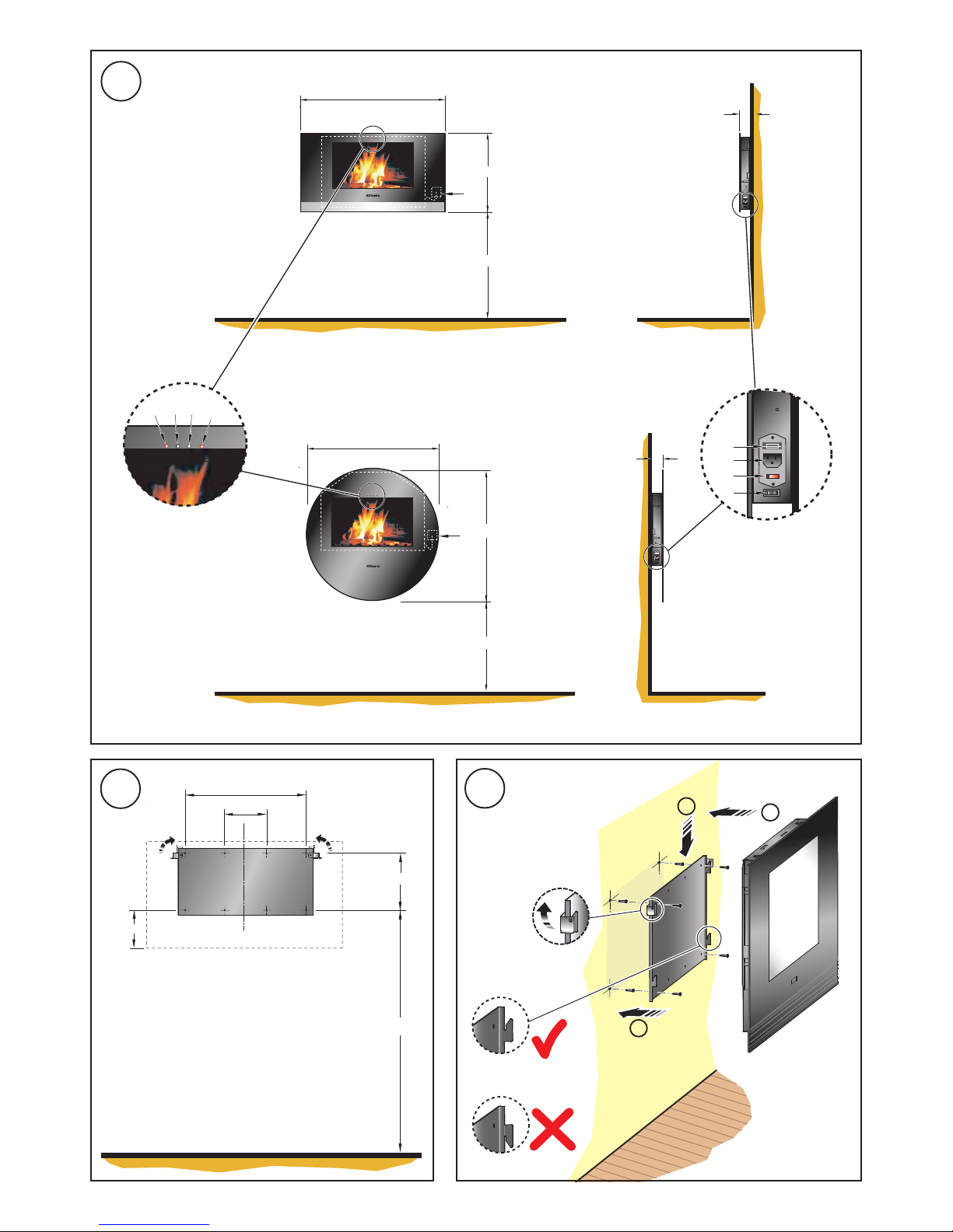
These models are designed to be permanently wall mounted
- see Fig. 1 for recommended fixing dimensions from floor to
underside of the appliance for optimum viewing of the display
screen. The outline of the chassis and the position of the
electrical socket are shown as dotted outlines in Fig. 1. Any
dimensions indicated
‘*’
are recommended dimensions.
The wall plate is secured to the chassis with 2 screws (see
detail view ‘X’ in Fig. 4). To wall mount the appliance first
remove the wall plate from the chassis by removing the two
screws and rotating the corner hinges away from the chassis.
Note : Retain the two screws for future use.
Fix the wall plate to the wall using the wall plugs and screws
provided. (Note: Ensure that the wall is suitable for the screws
& plugs provided).
Use the wall plate as a template to mark the hole positions
for drilling - see Fig. 2. Drill and fix the wall plate in position
with one screw initially to check the plate is level before
marking and drilling the remaining holes - see ‘1’ in Fig. 3.
Ensure the wall plate is fitted the correct way up i.e. the side
hooks are pointed upwards - see Fig. 3.
The appliance can then be fitted to the wall plate by aligning
the slots on the chassis with the side hooks on the wall
plate. This is best achieved by positioning the appliance
vertically above the plate (see ‘2’ in Fig. 3) and locating on the
side hooks and sliding the chassis downwards (see ‘3’ in
Fig. 3).
The corner hinges on the wall plate may be used to secure
the appliance against inadvertent dislodgement. Simply
rotate the hinges upwards (see Fig. 2 and detail view in Fig.
3) to a position above the chassis. They can then be screw
fixed using the screws removed earlier (see detail view ‘X’ in
Fig. 4 of corner hinge rotated up and screw fixed in position).
NOTE: The appliance should be ‘HARD’ wired to a fused
switched spur located behind the glass screen so as to be
hidden from view - see ‘a‘ in Fig. 1. The cable should be
shortened as necessary in order to remain concealed behind
the glass display screen.
Please consult a qualified electrician for appropriate wiring
requirements.
Page 5

Operation
Plug in the connector from the electrical hard wiring outlet to
the appliance (see ‘2’ in detail B Fig. 1).
The illuminated power ‘On’ switch (see ‘3’ in detail B Fig. 1)
must first be switched ‘On’ to operate the appliance either
manually or by remote control.
The ‘Coal’ scene will automatically come on when the power
‘On’ switch is switched on.
Switch the heat ‘On’ if required (see ‘4’ in detail B Fig. 1).
Heat ‘On’ will be indicated by a red LED (see ‘Y’ in detail ‘A’
Fig. 1).
Note: The temperature of the glass will rise steadily up to a
maximum of approximately 60 degrees C when the heat is
turned ‘on’.
The Memory Card (see ‘y’ in Fig. 6) as fitted is held in position
by a hinged cover (see ‘x’ in Fig. 6) which is screwed in place
to provide protection against damage in handling and for
added security - see C in Fig. 6.
If required the card can be removed by unscrewing and
hinging back the cover - see A in Fig. 6, and simply pre
ssing
down on the button (see ‘z’ in Fig. 6) beside the card to eject
it.
In replacing the card it should drop down into position before
pressing home – see B in Fig. 6 (force should not be used in
fitting the card as damage can result). Ensure the logo on
the card is facing down when inserting it, as shown in A in
Fig. 6.
Important: Always switch off the appliance before removing
the card.
Failure to do so will result in a picture freeze. To restart, the
appliance must first turned off at the illuminated power ‘On’
switch - see ‘3’ in detail B in Fig. 1 and the card pressed into
position, and then the illuminated power ‘On’ switch turned
on again.
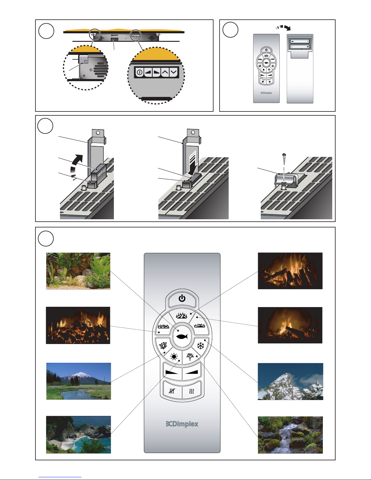
Manual Control Operation
The manual controls are located on top of the appliance
behind the glass screen (see detail view ‘Y’ in Fig. 4).
For description of manual button settings see below:
Standby Switch ‘On’ / ‘Off’
Audio volume ‘Down’
Audio volume ‘Up’
Scene selection ‘Up’
Scene selection ‘Down’
The manual Heat On/Off switch is located at the lower right
side of the appliance on Model LVA231 and at the lower left
hand side of Model LVA232 (see ‘4’ in detail B in Fig. 1).
Remote Control Operation
The remote control may be operated once the appliance is
switched ‘ON’. Select any one of eight scenes on your remote
control - see Fig. 7.
Each scene has it’s own particular sound effect which may
be activated and adjusted by pressing the audio volume
control buttons (
and ) to the level required, while
aiming the remote control at the IR sensors (see ‘a’ and ‘b’
in detail A in Fig. 1).
See below for button settings on remote control for various
scene selections:
‘Coal’ Fire scene
‘Log’ Fire scene
‘Embers’ Fire scene
‘Spring’ scene
‘Summer’ scene
‘Autumn’ scene
‘Winter’ scene
‘Aquarium’ scene
The heat may be switched On by pressing button (Heat
‘On’ is indicated by red LED (see ‘y’ in detail A in Fig. 1).
The heat may be turned Off by pressing button.
The appliance may be switched into Standby mode by
pressing the Standby On/Off button (see ‘x’ in detail A in
Fig. 1). Switching the appliance back On using the Standby
button will return to the scene that was on the screen before
turning it off. Alternatively any scene selected may be switched
on.
Note: When the appliance is switched into Standby mode the
heat will automatically be turned off, and if required when the
appliance is switched On again it must be independently
switched on remotely or manually as outlined in ‘Operation’.
Note: The user may notice a slight frame freeze lasting less
than 0.5 seconds after a scene has run for approximately 5
minutes.
This is normal and should not be a cause for concern.
The user has an option of turning heat On in Standby mode
without having a scene selected.
Remote Control Assembly
Note: The remote control is packed separately in the carton.
1. Slide open the battery cover on the back of the remote
transmitter.
2. Install the AAA batteries into the remote control (see
Fig. 5).
3. Replace battery cover.
Discard Leaking Batteries
Dispose of batteries in the proper manner according to
Provincial and local regulations. Any battery may leak
electrolyte if mixed with a different battery type, if inserted
incorrectly, if all the batteries are not replaced at the same
time, if disposed of in a fire or if an attempt is made to charge
a battery not intended to be recharged.
Page 6

Page 7

Recycling
For electrical products sold within the
European Community.
At the end of the electrical products useful
life it should not be disposed of with
household waste. Please recycle where
facilities exist. Check with your Local
Authority or retailer for recycling advice in
your country.
Cleaning
WARNING – ALWAYS DISCONNECT FROM THE POWER
SUPPLY BEFORE CLEANING THE APPLIANCE.
For general cleaning use a soft clean duster – never use
abrasive cleaners. The glass viewing screen should be
cleaned carefully with a soft cloth. DO NOT use proprietary
glass cleaners.
After Sales Service
Your product is guaranteed for one year from the date of
purchase.
Within this period, we undertake to repair or exchange this
product free of charge (subject to availability) provided it has
been installed and operated in accordance with these
instructions.
Your rights under this guarantee are additional to your statutory
rights, which in turn are not affected by this guarantee.
Should you require after sales service you should contact
our customer services help desk on 0870 727 0101. It would
assist us if you can quote the model number, series, date of
purchase, and nature of the fault at the time of your call. The
customer services help desk will also be able to advise you
should you need to purchase any spares.
Please do not return a faulty product to us in the first instance
as this may result in loss or damage and delay in providing
you with a satisfactory service.
Please retain your receipt as proof of purchase.
Page 8

Glen Dimplex UK Limited
Millbrook House
Grange Drive
Hedge End
Southampton
Hampshire. SO30 2DF
UK customer help line (8.00AM – 6.00PM Mon-Fri; 8.30AM-1.00PM Sat)
Customer Services: Tel. 0870 7270101
Fax. 0870 7270102
e-mail customer.services@glendimplex.com
Republic of Ireland Tel. 01 8424833
[c] Glen Dimplex UK Limited
All rights reserved. Material contained in this publication may not be reproduced in whole or in part, without prior permission in writing of Glen Dimplex UK Limited.
 Loading...