

Dimplex LST050, LST075, LST100, LST150 Operating Instructions Manual
These instructions should be read carefully and
retained for future use. Note also the information
presented on the appliance.
Low Surface
Temperature Heater
Models: LST050 / LST075 / LST100 / LST150
OPERATING
INSTRUCTIONS MANUAL
INDPUKP4RG ISSUE 2

IMPORTANT
These instructions should be read carefully and retained for future use.
Note also the information presented on the appliance.
IMPORTANT SAFETY ADVICE
When using electrical appliances, basic precautions should always be followed to reduce
the risk of fi re, electrical shock, and injury to persons, including the following:
IMPORTANT – The wall bracket supplied with the appliance must be used.
WARNING - DO NOT USE THIS HEATER IN THE IMMEDIATE SURROUNDINGS OF
A BATH, A SHOWER OR A SWIMMING POOL.
IMPORTANT – If the heater is installed in a room containing a bath or shower, it must be
so installed that switches and other controls cannot be touched by a person using a bath
or shower.
Do not use outdoors.
Do not locate the heater immediately below a fi xed socket outlet or connection box.
WARNING: In order to avoid overheating, do not cover the heater. Do not place material
or garments on the heater, or obstruct the air circulation around the heater, for instance
by curtains or furniture, as this could cause overheating and a fi re risk.
NEVER cover or obstruct in any way the heat outlet slots at the top of the heater or the air
inlet slots in the base of the heater.
The heater carries a warning ‘DO NOT COVER’ to alert the user to the risk of fi re that
exists if the heater is accidentally covered.
CAUTION - Some parts of this product can become very hot and cause burns. Particular
attention has to be given where children and vulnerable people are present. *
This appliance can be used by children aged from 8 years and above and by persons with
reduced physical, sensory or mental capabilities or lack of experience and knowledge if
they have been given supervision or instruction concerning use of the appliance in a safe
way and understand the hazards involved.
Children shall not play with the appliance. Cleaning and user maintenance shall not be
made by children without supervision.
Children of less than 3 years should be kept away unless continuously supervised.
Children aged from 3 years and less than 8 years shall only switch on/off the appliance
provided that it has been placed or installed in its intended normal operating position and
they have been given supervision or instruction concerning use of the appliance in a safe
way and understand the hazards involved. Children aged from 3 years and less than 8
years shall not plug in, regulate and clean the appliance or perform user maintenance.
Note that due care and consideration must be taken when using this heater in series
with a thermal control, a program controller, a timer or any other device that switches on
the heat automatically, since a fi re risk exists when the heater is accidentally covered or
displaced.
If the supply cord is damaged it must be replaced by the manufacturer or service agent or
a similarly qualifi ed person in order to avoid a hazard.
WARNING: Servicing and product repairs should only be undertaken by the manufacturers
approved service agent or a similarly qualifi ed person, using only exact manufacturer
approved spare parts.
*NOTE: In order to comply with European Standard 60335 we are obliged to include the
cautionary reference to surface temperature . However LST heaters are designed to meet
NHS Requirements for ‘Safe Hot Water and Surface temperatures’. LST surfaces do not
exceed 43C at 21C room temperature and therefore operate at signifi cantly lower surface
temperatures than allowable by the Standard.
2

WARNING – THIS APPLIANCE MUST BE EARTHED
The electrical installation must be carried out by a competent electrician, and be
in strict accordance with the current I.E.E. Regulations for Electrical Equipment in
Buildings. The wires in this mains lead are coloured in accordance with the following
code:
GREEN AND YELLOW: EARTH
BLUE:
NEUTRAL
BROWN
: LIVE
BLACK
PILOT WIRE
- see also ‘Pilot Wire Connection’.
The heater is fi tted with a length of fl exible cable type H05VV-F size 4 x 1.0mm
2
for
connection to the fi xed wiring of the premises through a suitable connection box
positioned adjacent to the heater.
A means for disconnection must be incorporated in the fi xed wiring of the premises
in accordance with the wiring rules. The supply circuit to the heater must incorporate
a double pole isolating switch having a contact separation of at least 3mm.
Pilot Wire Connection
The BLACK control wire is designed to carry a signal from a wall mounted Dimplex
programmer. If a programmer is not being used, the pilot wire should be isolated in
accordance with the current IEE Wiring Regulations.
IMPORTANT - DO NOT connect the BLACK pilot wire to earth. Care should be taken
with the installation of the pilot wire(s) as when switching to background (setback)
they become energised at 240V although only at a current of less than 100mA. In
every case a suitable means of isolation must be provided for the pilot wire and
marked to indicate that two sources of supply may be present at the heater. Where
pilot wires are installed separately from the heater fi nal sub-circuit they should be
protected, double insulated and carry their own integral earth continuity conductor.
Supplementary Earth Bonding
Should Equipotential Earth Bonding be required the earthing conductor in the supply
cord is deemed to provide the supplementary bonding connection (see Regulation
544.2.5, 17th Edition I.E.E. Wiring Regulations).
Please note that lit cigarettes, candles and oil burners, combined with the
convection effect of electric heaters can cause soot deposits to build up on the
surface directly above and to the sides of the heater. This is not a fault of the
heater. Extensive burning of candles or smoking in the operating environment of
this product can produce heavy discolouration within a few months of use.
3

General
The heater is designed for wall mounting using the wall bracket supplied.
It should only be operated when in the upright position as shown - see Fig. 3
and Fig. 4. All models are splash proof to IP24 standard and may be used in
bathrooms, however not in the immediate vicinity of baths, showers, water
connections, wash basins or swimming pools. Before connecting the heater
check that the supply voltage is the same as that stated on the heater.
Dimensions
Model(s) Watt (kW) A (mm)
LST050 0.5 kW 688
LST075 0.75 kW 688
LST100 1.0 kW 688
LST150 1.5 kW 860
see Fig. 3
Wall Mounting
IMPORTANT – The wall bracket supplied with the appliance
must be used. The heater should be positioned observing the
minimum clearances stated around the heater - see
Fig. 2, Fig. 3 and Fig. 4.
DO NOT locate the heater immediately below a fi xed socket
outlet or connection box.
1. Remove wall mounting plate from the back of the
heater by fi rstly removing the M4x20 screw with a
Pozi Head No.2 screwdriver see Fig 1.
2. Fix the wall bracket securely to the wall through the
four screw holes provided see Fig 2.
3. Present the wall brackets on the heater to the wall
mounting plate and engage lower slots in the wall
brackets to the hooks on the wall mounting plate.
4. Position the top slots onto the top hooks and slide the
heater downwards until the slots come to a positive stop.
5. Re-insert the M4x20 screw in the M4 clinch nut on the
wall bracket. This secures the heater to the wall plate.
4
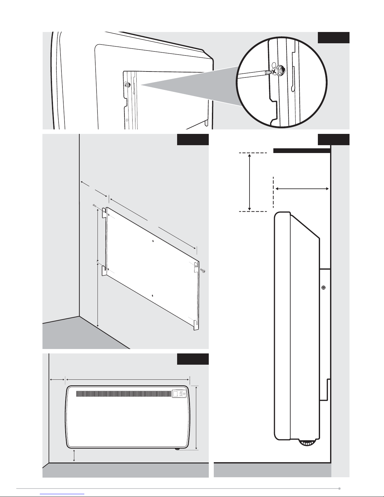
Fig. 1
Fig. 3
A
150 mm (Min)
430 mm
150 mm (Min)
50 mm
108 mm
Shelf
Fig. 4
A
168 mm 270 mm (min)284 mm
Fig. 2
Model (s) A (mm)
LST050 406
LST075 406
LST100 406
LST150 504
5
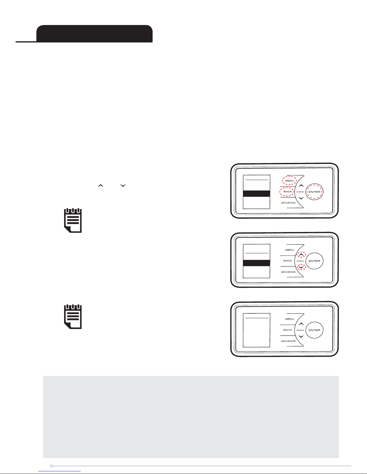
Notes to the Installer
Test Mode
When the heater is connected via a pilot wire system, the test mode allows
the installer to confi rm that the heater is responding correctly to the incoming
pilot wire signal.
Pilot wire mode must be enabled in the heater’s settings in order for the
appliance to be controlled by a Dimplex controller with pilot wire connection.
Press MENU, BACK and ENTER for ten seconds to enter the service
menu, select Pilot Wire and press ENTER. Select Enable.
Safety - Overheat protection
Note: Some features are
not available while pilot
wire mode is enabled.
Test Mode
Pilot Wire
Status
Comfort
Time
remaining
4:00
Comms
Standalone
RF Module
Pilot Wire
Select
Comfort SP
21 °C
For your safety this appliance is fi tted with
a thermal cut-out. In the event that the
product overheats for some reason, the cut-
out prevents excessive temperatures on the
product by cutting the power to the heater.
Once the heater has cooled down, it will reset
automatically, it will continue to cycle
on and off automatically until the reason for
overheating is removed.
The display screen will fl ash red to indicate the
product has overheated. To reset the display,
remove the obstruction and hold ENTER for
10 seconds.
The desired comfort temperature should be
selected using
and . Press ENTER to confi rm.
The heater will now enter a test state for four
minutes. During this test state the display screen will
indicate the pilot wire status. Each pilot wire mode
should be verifi ed to ensure correct operation.
Note: The comfort
temperature can be
changed later if required.
6
 Loading...