

Page 1

Smart Baseboard
LPC Series
IMPORTANT INSTRUCTIONS
When using electrical appliances, basic precautions should al-
ways be followed to reduce the risk of re, electric shock and
injury to person, including the following:
1. Read all instructions before using this heater.
2. Heater and controls should be installed by a qualied con-
tractor. Wiring procedures and connections should be in
accordance with the National Electric Code (CEC & NEC)
and local codes.
3. A heater has hot and arcing or sparking parts inside. Do
not use it in areas where gasoline, paint or ammable liquids are used or stored.
4. This heater is hot when in use. To avoid burns, do not let
bare skin touch hot surfaces. Keep combustible materials
such as: furniture, pillows, bedding, papers, clothes and
curtains away from heater.
5. To prevent a possible re, do not block air intakes or ex-
haust in any manner. Do not use on soft surfaces like a
bed where openings may become blocked.
6. Do not insert or allow foreign objects to enter any ventilation or exhaust opening as this may cause an electric
shock or re, or damage the heater.
7. Do not install these heaters against combustible, low den-
sity cellulose bre surfaces or vinyl wall paper.
8. Do not locate these heaters below any electrical convenience receptacles.
9. Check nameplate ratings to be sure the heater voltage is
the same as the service supply. (The nameplate is located
below the right side of the heating element.)
10. HIGH TEMPERATURES: Keep electrical cords, furniture,
draperies or any other blocking material away from the
heater. See Installation Section for specic distances.
SAVE THESE INSTRUCTIONS
This equipment has been tested and found to comply with the
limits for a Class B digital device, pursuant to Part 15 of the
FCC Rules. These limits are designed to provide reasonable
protection against harmful interference in a residential installation. This equipment generates uses and can radiate radio
frequency energy and, if not installed and used in accordance
with the instructions, may cause harmful interference to radio
communications. However, there is no guarantee that interference will not occur in a particular installation. If this equipment
does cause harmful interference to radio or television reception, which can be determined by turning the equipment off
and on, the user is encouraged to try to correct the interference by one of the following measures:
• Reorient or relocate the receiving antenna.
• Increase the separation between the equipment and
receiver.
• Connect the equipment into an outlet on a circuit different from that to which the receiver is connected.
• Consult the dealer or an experienced radio/TV technician for help.
This device complies with Part 15 of the FCC Rules. Operation is subject to the following two conditions: (1) This device
may not cause harmful interference, and (2) this device must
accept any interference received, including interference that
may cause undesired operation.
FCC CAUTION: Any changes or modications not express-
ly approved by the party responsible for compliance could void
the user’s authority to operate this equipment.
This device complies with Industry Canada licence-exempt
RSS standard(s). Operation is subject to the following two
conditions: (1) this device may not cause interference, and (2)
this device must accept any interference, including interference that may cause undesired operation of the device.
Installation Instructions
Placement of the Smart Baseboard
Smart Baseboards are high performance heaters designed
to operate at higher outlet temperatures than conventional
baseboard heaters. They can be directly mounted onto drywall, plaster, wood or concrete walls. Due to the higher outlet
temperature, the wall surface can reach temperatures of 160º
F (71º C) or above and some materials may discolor or deform
at these temperatures, e.g. vinyl or plastic. In these cases the
heater can be mounted with an offset from the wall and oor to
reduce the temperature being applied to those materials. By
installing the heater with the provided Installation Optimizer
kit, the temperature of the wall above the heater can be reduced to 129º F (54º C).
!
NOTE: If the unit is being installed on a newly constructed
wall, ensure that all products that have been applied are
fully cured according to manufacturer’s instructions, before
operating the unit.
Recommendations for Locating Drapes and Furniture near Heater (Figure 1)
!
NOTE: Any objects or materials that are located within the
distances outlined below should not discolor, nor distort
dimensionally (stretch or shrink) upon extended exposure (
up to 1000 hrs.) to temperatures of 200º F (93º C).
For most satisfactory operation of the heaters and minimum
effect on drapes, furniture and objects in close proximity, the
following recommendations should be observed:
1. Full Length Drapes: Hang drapes so there is at least 1.5”
(3.8 cm) between the top of the drapes and the ceiling, at
least 1.5” (3.8cm) between the bottom of the drapes and
the nished oor covering (such as carpet, if used) AND at
least 3” (7.6 cm) between the front vertical surface of the
heater and the nearest fold of the drapes (opened drape).
(Figure 1A)
2. Shorter Length Drapes: Hang drapes so there is at least
1.5” (3.8 cm) between the top of the drapes and the ceiling,
and at least 6” (15.2 cm), preferably more, between the
bottom of the drapes and the top horizontal surface of the
heater. (Figure 1B)
7211700100R18
Page 2
3. Furniture: Place furniture no closer than 3” (7.62 cm) from
the front of the Smart Baseboard. (Figure 1D)
4. Overhanging Solid Objects (Except Plastic): Position
Smart baseboard so there is at least 14” (35.6 cm) between
the top of the heater and any solid object that obstructs or
redirects the vertical air ow out of the top of the unit. (Figure 1C)
5. Overhanging Plastic Objects: All Plastic items that cannot withstand extended exposure to temperatures 60º C or
higher should be kept a minimum of 20” (50.8cm) above the
unit. (Figure 1C))
!
NOTE: Ensure that when 2 Smart Baseboards are installed
near the same corner they are both a minimum of 6” from
the corner.
Installation
All Smart Baseboards must be connected from the right side
of the heater.
!
NOTE: The left hand end of the enclosure can be used as
a junction box and the space under the heater can be used as
a wireway.
CAUTION: Disconnect power supply before installation to
prevent electric shock.
1. Unpack and place Smart Baseboard on oor face up, use
packaging to protect oor if required. Remove front covers.
!
NOTE: Remove the center cover, by releasing the top
rst.
!
NOTE: Heater ns can be easily bent. For optimal per-
formance ensure that they remain vertical.
2. Orient unit in desired location and mark pilot holes - top and
bottom at both ends and at least one set in middle.
3. Wire unit as per diagrams (below) and National and Local
Electrical Codes.
CAUTION: Connect heaters to a branch circuit used only
for permanently installed heater and protected by over current devices rated or set at no more than 30 amperes. The
total connected load should not be more than 80% of the
rating of the over current devices. It may cause a re hazard if not installed and maintained in accordance with these
instructions.
4. Position LPC, pushing cable back into wall (or conduit), run
screws through pre-selected mounting holes and spacers
(if applicable), using appropriate wall anchors, if necessary.
!
NOTE: Screw should be backed off 1/2 turn from snug
position to allow free expansion and contraction of housing
and to ensure quiet operation.
5. Replace covers on unit.
!
NOTE: Install the center cover rst, by installing the top
rst, then the bottom.
Usage of Multiple Smart Baseboards
Multiple Smart Baseboards can be wired in parallel on a single
circuit. To use/control multiple Smart Baseboards from a single
source, a CONNEXTM controller can be used. By synchronizing one CONNEXTM controller to multiple LPC’s, the controller
can control all of the heaters from one location. Each compo-
nent must be within 15m (45ft) of any other component in the
system for the entire system to operate.
Operation
1. This smart baseboard must be properly installed before it
is used.
2. Prior to energizing, remove all construction dirt (plaster,
sawdust, etc.) from interior and exterior of smart baseboard.
Dimplex smart baseboards are designed and tested for safe
and trouble-free operation. All Dimplex smart baseboards are
protected against overheating by a built-in thermal cutout.
Free airow throughout the smart baseboard is very important for the most efcient operation of the smart baseboard.
Restricted airow may cause the thermal overload protector
to cycle the smart baseboard “ON and OFF”. A cycling smart
baseboard will not supply sufcient heat to the room.
CAUTION: Avoid direct contact of paper, fabric, or furniture
with smart baseboard, to prevent a possible re.
When power is rst supplied to the LPC the Setpoint Temperature will ash in the temperature display area. At any time ei-
ther the + or - button can be pressed to have the temperature
setpoint displayed again.
A. Setting/Temperature Display
The LPC is designed to control the temperature of a room anywhere from 32-86°F (0-30°C). Pressing the + or - will increase
or decrease the desired temperature for the room to be heated
by 0.5° (in either °C or °F).
After 5 seconds the Setpoint Temperature will switch to display the intake temperature of the room.
!
NOTE: Pressing the + and - at the same time will toggle
between °C and °F.
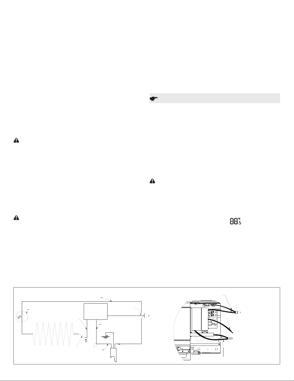
Wiring Diagram
Black - Element Return Wire
LPC
Thermal Cutoff
Yellow - Control Wire
Black - Element Wire
2 www.dimplex.com
Control Board
Blue - Control Wire
Black - Control Wire
Ground
L2 / Neutral
L1
Blue control wire and black element return wire are connected.
Connect L2/Neutral to these during installation.
Yellow control wire and black element wire are connected.
Do not change during installation.
Black wire from control.
Connect L1 to this during installation.
Page 3

Figure 1
3" (7.6 cm)
A B C D
Min.
1.5" (3.8 cm)
Min.
1.5" (3.8cm)
Min.
Min.
1.5" (3.8 cm)
Min.
6" (15.3 cm)
Min.
See Item 4 & 5
for Dimension
Min.
3" (7.6 cm)
Min.
3" (7.6 cm)
Figure 2
A
C
B
D
E
A - Setting/Temperature Display
B - Economy Setting Icon
C - Set Back Temperature Setting
D - Comfort Setting Icon
E - Synchronized Icon
B. Economy Setting
H
G
F
F - Lock Icon
G - Decrease Button
H - Increase Button
I - Menu Button
I
The Economy Setting can be used to change the Setpoint
Temperature for a variable period of time. By pressing the V
the Economy Setting will be enabled - signied by the icon
ashing. After the Set Back Temperature has been set, the
icon will become solid after three seconds and the Set Back
Temperature will be enabled.
To return back to the Comfort Setting press the V button and
the icon will disappear and the icon will appear.
C. Set Back Temperature Setting
The Set Back Temperature Setting is used during periods
when the Economy setting feature is active. This temperature adjustment can be set by pressing the V followed by the
+ or -.
D. Comfort Setting
The Comfort Setting icon will be displayed when the heater
is in normal operation based on the Setpoint Temperature for
the room.
!
NOTE: Either the or icon will always be visible, de-
pendent on the setting being used.
E. Synchronized Icon
The LPC features CONNEXTM, a wireless technology that
works with Dimplex single and multi-zone CONNEXTM control-
lers to provide simple whole home connectivity and comfort.
CONNEXTM controllers are available to control one or multiple
LPC’s or PCH’s within a 50’ (15 m) radius. In order for the
controller to have this function the LPC and the controller will
need to be synchronized. To do this:
1. On the LPC heater press and hold the V button for 3 sec-
onds, both the and icons will begin to ash.
2. Press the - , + and then V, on the LPC heater.
3. Within 10 seconds press any button once on the CON-
NEXTM controller.
!
NOTE: There is a 3 second delay between pressing the last
button on the CONNEXTM controller and the LPC heater.
!
NOTE: To desynchronize a LPC heater from the synchro-
nized CONNEXTM controller, on the LPC heater:
1. Press and hold the V for 3 seconds.
2. Press the V, + and then -.
Nothing needs to be done to the CONNEXTM controller.
Dimplex single and multi-zone CONNEXTM controllers are sold
separately and are available for purchase from your authorized Dimplex dealer.
To nd your local Dimplex dealer, visit www.dimplex.com.
F. Lock Icon
The Smart Baseboard has a Button Lock feature, to prevent
settings from accidentally being changed.
1. Press and hold the V for 3 seconds. Both the and
Icons will begin to ash.
2. To Enable: Within 5 seconds press +, then -, then +, then
-. The icon will now be visible.
To Disable: Within 5 seconds press -, then +, then -, then
+. The icon will not be visible.
!
NOTE: The LPC can be locked in either the Comfort or
Economy Setting. Ensure that the desired icons are present
when locking is complete.
Maintenance
CAUTION: Before removing the front cover for cleaning,
make certain the power has been turned off at the circuit
breaker panel, to prevent electric shock.
CAUTION: To avoid burns, allow adequate time for the ele-
ment and body casing to cool before attempting to work on
the smart baseboard.
The LPC series contain no moving parts. Since the appliance
contains no moving parts, little maintenance is required beyond vacuum cleaning. It is however essential that the smart
baseboard is not operated with an accumulation of dust or dirt
on the element, as this can cause a build up of heat and eventual damage. For this reason the smart baseboard must be
inspected regularly, depending upon conditions and at least at
yearly intervals. Once cleaning is complete replace the front
cover and restore power.
!
NOTE: The user can perform cleaning ONLY. All other ser-
vicing should be performed by qualied service personnel.
Warranty
The Manufacturer warrants the Smart Baseboard and components of the enclosed product against any defect in material or workmanship for a period of one year from the date of
purchase, with the exception of the elements which are warranted to be free from defect in material and workmanship for
ten years. In full satisfaction of any claims under this Warranty
the Manufacturer will repair or replace without charge, in its
factory or in the eld as it alone may decide, any parts which
3
Page 4

in its opinion are defective.
The Manufacturer shall not be responsible for any transporta-
tion or shipping costs in relation to such repair or replacement
except as specically assumed by it. Misuse of this product or
repairs by persons other than the Manufacturer’s authorized
personnel without the Manufacturer’s written approval will void
this Warranty.
This Warranty is in lieu of all other warranties or conditions
whether expressed or implied including but not limited to those
of merchantability or tness for purpose and shall constitute
the sole remedy of the Purchaser and the sole liability of the
Manufacturer in respect of the sale of the product, whether
in the nature of breach or breach of fundamental term, or of
negligence or otherwise.
The Manufacturer shall not be liable for any special, indirect
or consequential damages or for any damages resulting from
removal or replacement of a Smart Baseboard subject to warranty claim without the Manufacturer’s authorization.
This Warranty is transferable by the original consumer purchaser of the product. Any claims under this Warranty must
be submitted in writing to the Service Manager, Dimplex North
America Ltd., 1367 Industrial Rd., Cambridge, Ontario N3H
4W3, Canada.
1367 Industrial Road Cambridge ON Canada N3H 4W3
1-888-346-7539 www.dimplex.com
In keeping with our policy of continuous product improvement, we reserve the right to make changes without notice.
© 2016 Dimplex North America Limited
 Loading...