

Dimplex LIAC12IM6, LIAC14IM6, LIAC16IM6, LIAV12IM, LIAV14IM Operating Instructions Manual
...Page 1
F567486
Operating Instructions
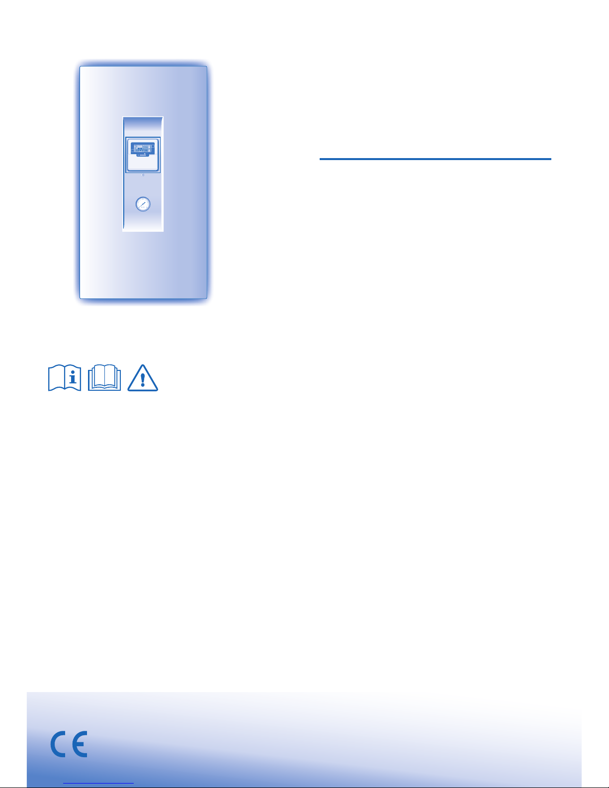
Air-to-Water Heatpump
Model No.
Indoor Unit
Outdoor Unit
LIAC12IM6 LIAV12IM
LIAC14IM6 LIAV14IM
LIAC16IM6 LIAV16IM
ENGLISH
ENGLISH
Before operating the unit, read these operating instructions thoroughly and keep them for future reference.
Before operating the unit, make sure the installation has been carried out correctly by authorized dealer correctly and
precisely following the installation instructions given.
2 ~ 9
2 ~ 9
FRANÇAIS
FRANÇAIS
Avant d’utiliser l’appareil, lisez ce mode d’emploi dans son intégralité et conservez-le pour toute référence ultérieure.
Avant de faire fonctionner l’unité, assurez-vous que l’installation a été correctement réalisée par un revendeur agréé
et dans le strict respect des consignes d’installation fournies.
10 ~ 17
10 ~ 17
ESPAÑOL
Antes de utilizar la unidad, sírvase leer atentamente estas instrucciones de funcionamiento y conservarlas como
futuro elemento de consulta.
Antes de operar la unidad asegúrese de que la instalación haya sido realizada correctamente por un distribuidor
autorizado, siguiendo de forma correcta y precisa las instrucciones de instalación dadas.
18 ~ 25
18 ~ 25
DEUTSCH
Bevor Sie das Gerät in Betrieb nehmen, lesen Sie bitte diese Bedienungsanleitung aufmerksam durch und bewahren Sie
sie für die künftige Verwendung auf.
Vor der Inbetriebnahme dieses Geräts ist sicherzustellen, dass die Montage durch einen autorisierten Händler
fachgerecht entsprechend der Installationsanleitung durchgeführt wurde.
26 ~ 33
26 ~ 33
0.2
0.40
0.30.1
MPa
TIMER OUTDOOR
HEAT
SETTING
STATUS
PUMPDW
BOOSTER
QUIET
TANK
WATER OUTLET
C
C
OFF
/
ON
HEATER
OPERATION
FORCE
HEATER
ACTUAL
TIMER
1
MONTUEWEDTHUFRI SAT SUN
SOLAR REMOTE
NOT AVAILABLE
23 4 56
ON
OFF
Page 2
2
• This manual describes how to operate the Heatpump system
between indoor and outdoor units only.
•
Other operation such as water tank, radiator, external thermo controller
and underfl oor system, please refer to respective manufacturer
operation manuals.
SAFETY PRECAUTIONS
TABLE OF CONTENTS
TABLE OF CONTENTS
SAFETY PRECAUTIONS
2~3
CONTROL PANEL
4~7
INDOOR UNIT
8
TROUBLESHOOTING
9
INFORMATION
34~35
NOTE
NOTE
The illustrations in this manual are for
explanation purposes only and may
differ from the actual unit. It is subjected
to change without notice for future
improvement.
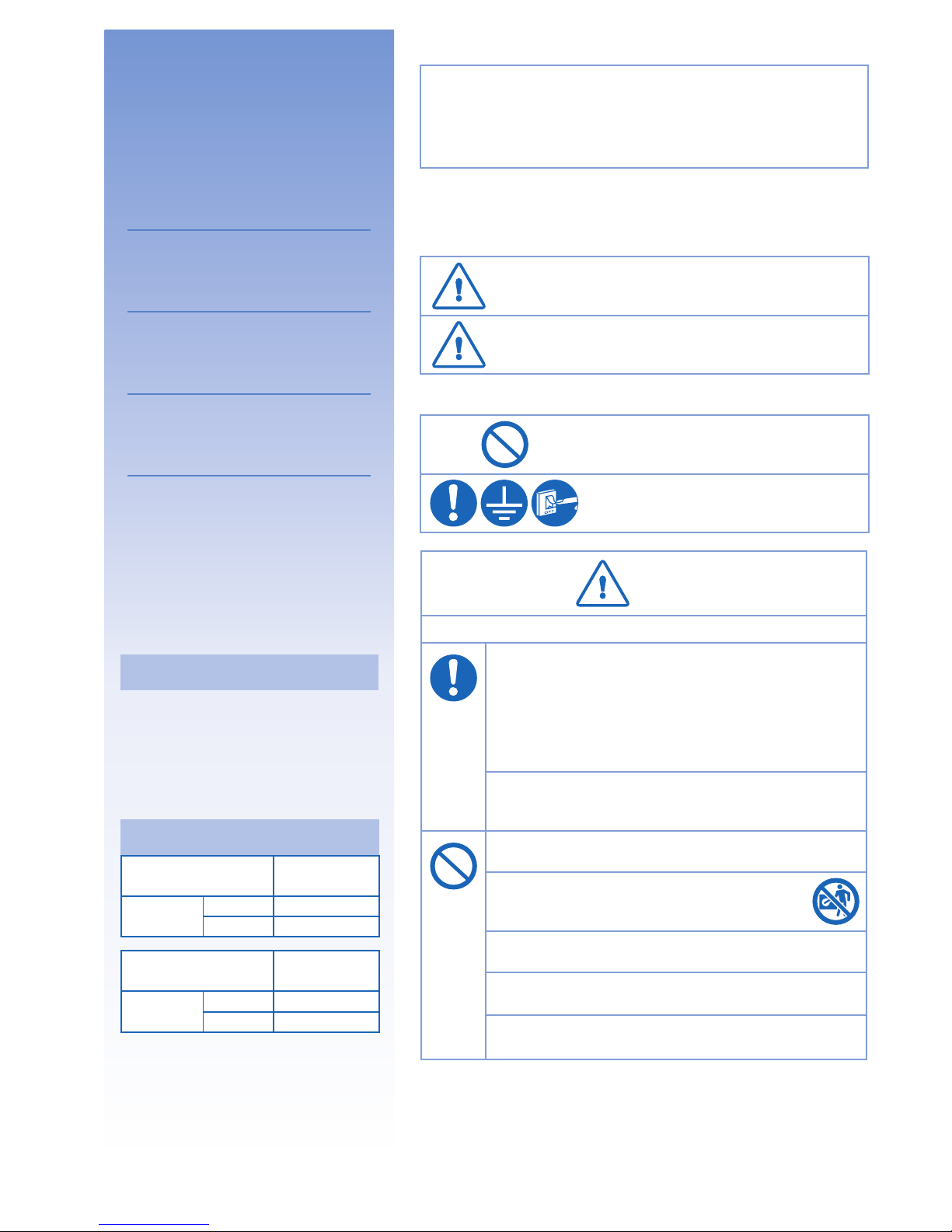
OPERATION CONDITION
OPERATION CONDITION
Water outlet
Temperature (°C)
Indoor
HEATING
Max. 55
Min. 25
Ambient
Temperature (°C)
Outdoor
HEATING
Max. 35
Min. -20
NOTICE :
When the outdoor temperature
is out of the above temperature
range, the heating capacity will
drop signifi cantly and outdoor
unit might stop for protection
control.
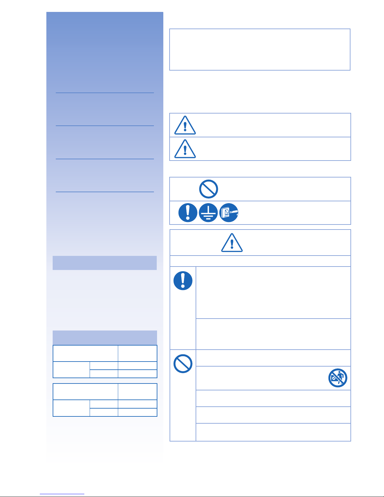
To prevent personal injury, injury to others, or property damage, please
comply with the following.
Incorrect operation due to failure to follow instructions below may cause
harm or damage, the seriousness of which is classifi ed as below:
WARNING
WARNING
This sign warns of death or serious injury.
CAUTION
CAUTION
This sign warns of injury or damage to
property.
The instructions to be followed are classifi ed by the following symbols:
This symbol denotes an action that is
PROHIBITED.
These symbols denote an actions that
is COMPULSORY.
WARNING
WARNING
INDOOR UNIT AND OUTDOOR UNIT
This appliance is not intended for use by persons (including
children) with reduced physical, sensory or mental
capabilities, or lack of experience and knowledge, unless
they have been given supervision or instruction concerning
use of the appliance by a person responsible for their safety.
Children should be supervised to ensure that they do not
play with the appliance.
Please consult authorized dealer or specialist to repair,
install, remove and reinstall the unit. Improper installation
and handling will cause leakage, electric shock or fi re.
Do not install the unit in a potentially explosive or fl ammable
atmosphere. Failure to do so could result in fi re.
Do not insert your fi ngers or other objects into the
air conditioner indoor or outdoor unit, rotating parts
may cause injury.
Do not touch the outdoor unit during lightning, it may cause
electric shock.
Do not attempt to repair the unit by yourself. Otherwise,
it may cause injury if it is mishandling.
Do not install the indoor unit at outdoor. This is designed for
indoor installation only.
Page 3
ENGLISH
3
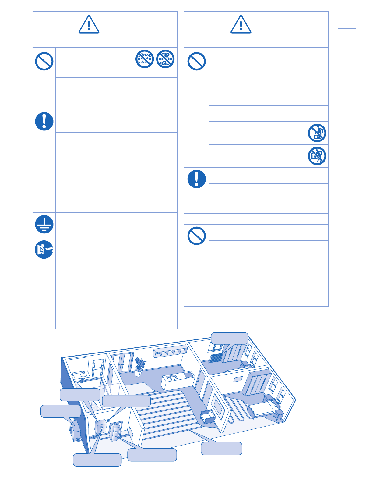
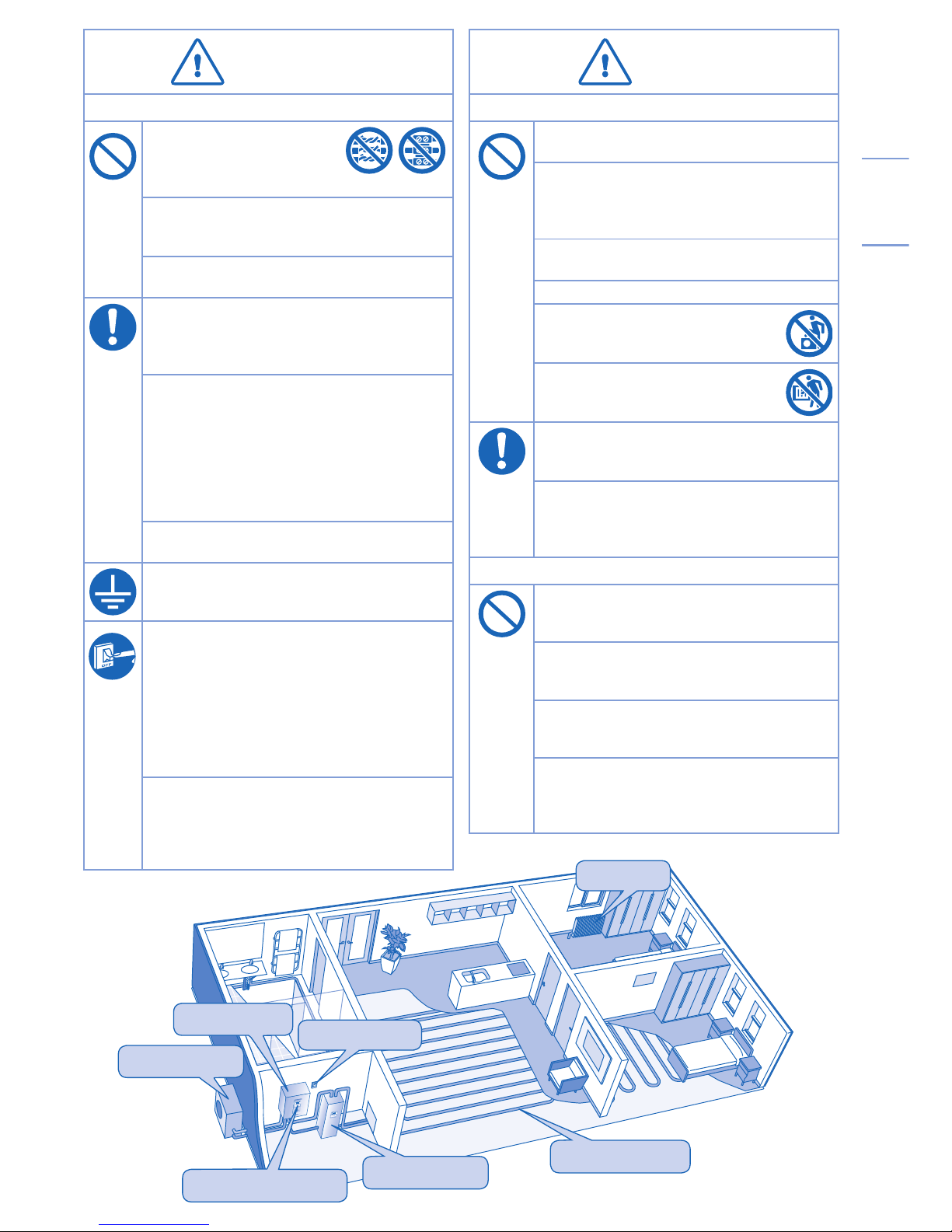
/
/
Floor Heating
Panel
Control Panel
Power Supply
Water Tank Unit
Indoor Unit
Outdoor Unit
CAUTION
CAUTION
INDOOR UNIT AND OUTDOOR UNIT
Do not wash the indoor unit with water,
benzene, thinner or scouring powder.
Do not install the unit close to any combustible
equipment or at bathroom. Otherwise, it may
cause electric shock or fi re.
Do not touch the water discharge pipe at the
indoor unit during operation.
Do not place anything on top or beneath of the
unit.
Do not sit or step on the unit, you
may fall down accidentally.
Do not touch the sharp aluminium fi n,
sharp parts may cause injury.
Ensure drainage pipe is connected properly.
Otherwise, leakage may occur.
Check the installation rack periodically to make
sure that it is not damaged. After long periods
of use, the strength of the installation rack may
have deteriorated.
CONTROL PANEL
Do not let the control panel get wet. Otherwise,
it may cause electric shock or fi re.
Do not press the buttons on the control panel
with hard, pointed objects. Otherwise, it may
damage the unit.
Do not wash the control panel with water,
benzene, thinner or scouring powder.
Do
not inspect or service the control panel by
not inspect or service the control panel by
yourself. Please consult authorized dealer.
yourself. Please consult authorized dealer.
Otherwise, it may cause injury if mishandling.
WARNING
WARNING
POWER SUPPLY
Do not use modifi ed cord,
joint cord, extension cord or
unspecifi ed cord to prevent
overheating and fi re.
Do not share the same power outlet with other
equipment to prevent overheating and fi re.
Do not operate with wet hands to prevent electric
shock.
If the supply cord is damage, it must be replaced
by the manufacturer, its service agent or similarly
qualifi ed persons in order to avoid a hazard.
This unit is equipped with Residue Current
Circuit Breaker (RCCB). It is strongly
recommended to check the operation of the
RCCB after installation and periodically after
servicing or maintenance by authorized dealer
to ensure it is in good working order. Otherwise,
it may cause electrical shock or fi re in case of
malfunction.
It is recommended to wear gloves during
servicing or maintenance in order to avoid
hazard.
This equipment must be earthed to prevent
electrical shock or fi re.
In case of emergency or abnormal conditions
(burnt smell, etc), turn off the power supply, and
please consult authorized dealer.
Prevent electric shock by switching off the power
supply when:
- Before cleaning or servicing.
- Extended non-use.
- Abnormally strong lightning activity.
This appliance is for multiple uses. All power
supply circuits must be turn off before access to
any of the terminals in the indoor unit, to avoid
electrical shock, burn or fatal injury.
Page 4
4
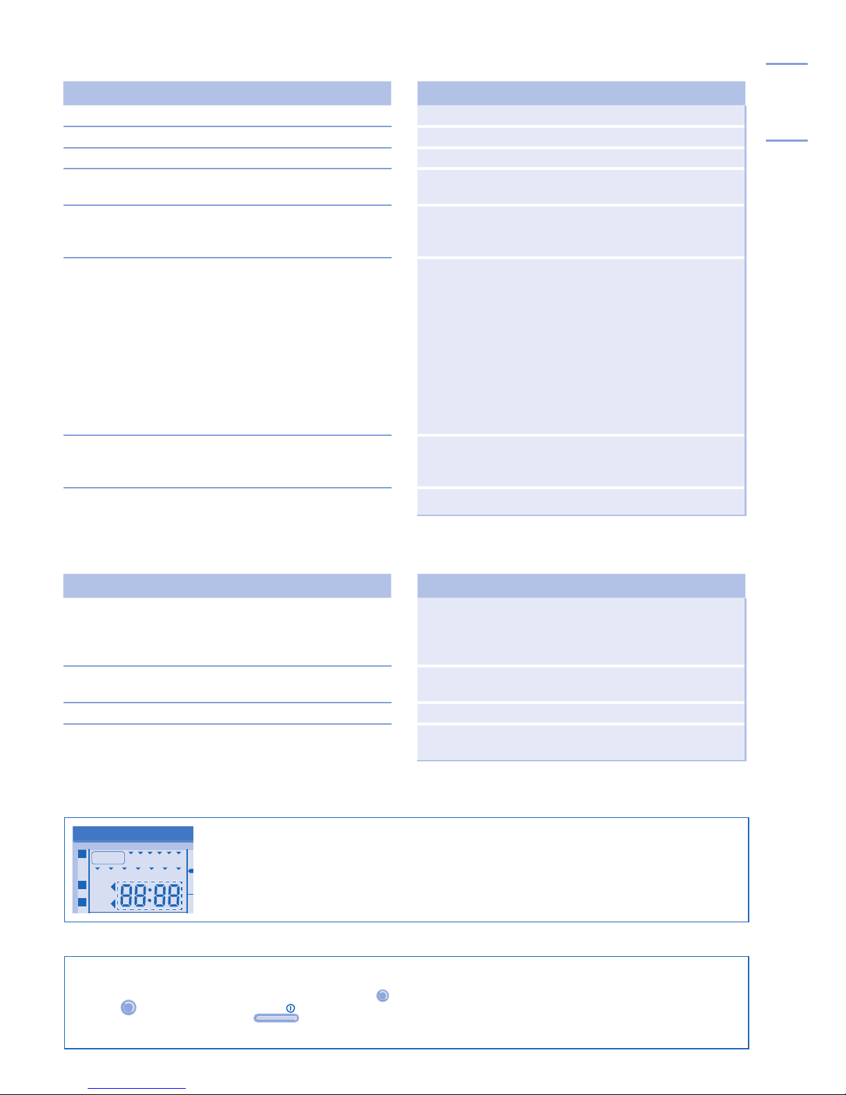
CONTROL PANEL
TIMER OUTDOOR
HEAT
SETTING
STATUS
PUMPDW
BOOSTER
QUIET
TANK
WATER OUTLET
C
C
SET
SELECT
CANCEL
ERROR
RESET
SETTING
STATUS
SEARCH
PUMPDWFORCECLOCK
CHECK
OFF
/
ON
MODE
HEATER
QUIET
OFF/ON
TIMER
HEATER
OPERATION
FORCE
HEATER
ACTUAL
TIMER
1
MON TUEWEDTHU FRI SAT SUN
REMOTE
2 3 4 56
ON
OFF
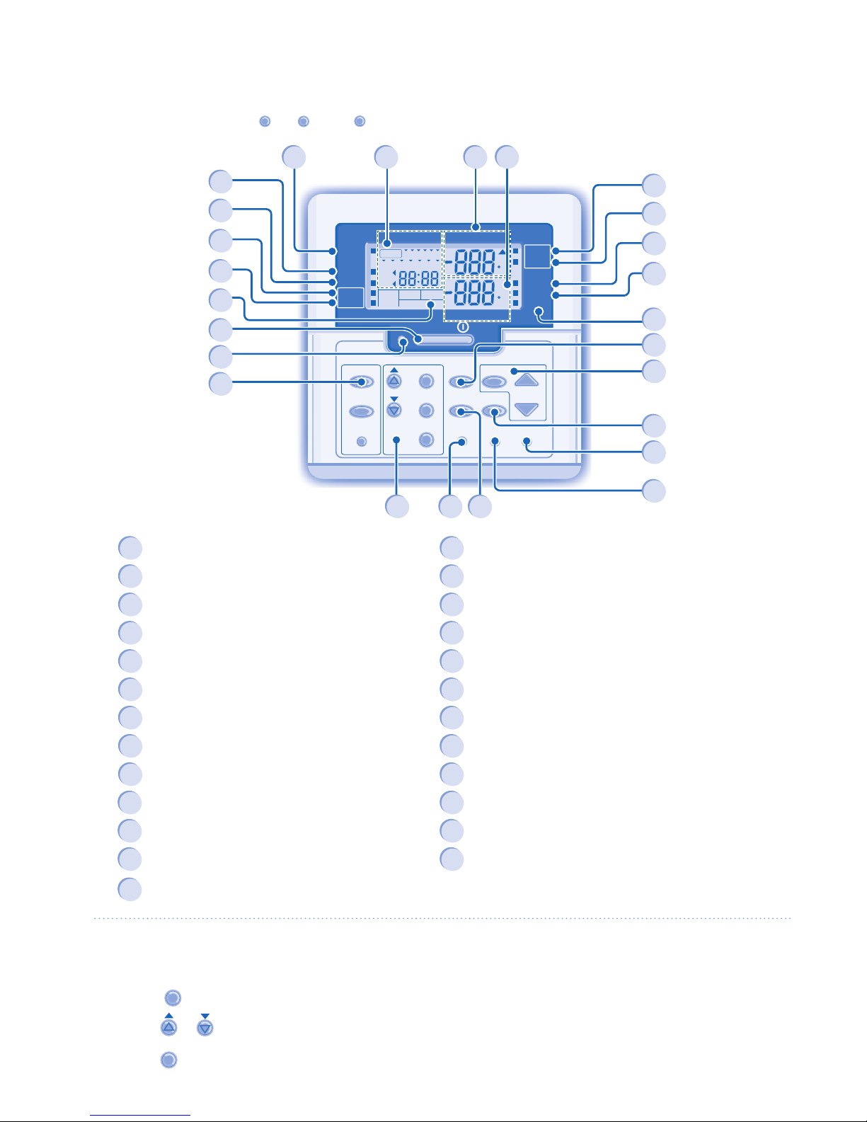
• Some functions described in this manual may not be applicable to your unit.
• Consult your nearest authorized dealer for further information.
• For normal operation, the
ERROR
RESET
,
FORCE
and
PUMPDW
buttons are not in use.
1
OFF/ON Button
14
Quiet Operation OFF/ON Indicator
2
Operation LED
15
Backup Heater Request OFF/ON Indicator
3
Operation Mode Button
16
Force Heater Request OFF/ON Indicator
4
Quiet Operation Button
17
Backup Heater Actual Operation (OFF/ON) Indicator
5
Indoor Unit Backup Heater Operation Button
18
Booster Heater Actual Operation (OFF/ON) Indicator
6
System Setting Mode Buttons
19
System Setting Mode OFF/ON Indicator
7
Timer Setting Group Buttons
20
System Status Check Mode OFF/ON Indicator
8
Force Heater Mode Button
21
System Pumpdown Mode OFF/ON Indicator
9
System Pumpdown Mode Button
22
Timer/Clock Setting Display
10
System Status Check Mode Buttons
23
Remote Display
11
Error Reset Button
24
Outdoor Ambient Temperature Display
12
Heat Mode OFF/ON Indicator
25
Water Outlet Temperature Display
13
Tank Mode OFF/ON Indicator
Notes:
• The current day and time need to be set when:
- The power is turned on for the fi rst time.
- After a long time has elapsed since the power was last
turned on.
• The current time that has been set will be the standard
time for all the Timer operations.
1. Press
CLOCK
.
2. Press
or to set current day.
3. Press
SET
to confi rm.
4. Repeat steps 2 and 3 to set the current time.
CONTROL PANEL PREPARATION
Setting Current Day and Time
16
1
22
21
10
17
18
19
20
24
9
5
25
3
8
4
7
2
15
14
12
13
6 11
23
Page 5
ENGLISH
5
SETTING UP THE SPECIAL FUNCTIONS
SETTING UP THE SPECIAL FUNCTIONS
• After initial installation, you can manually adjust the settings. The initial setting remains active until the user changes it.
• The control panel can be used for multiple installations. Some functions may not be applicable to your unit.
TIMER OUTDOOR
HEAT
SETTING
STATUS
PUMPDW
BOOSTER
QUIET
TANK
WATER OUTLET
C
C
HEATER
OPERATION
FORCE
HEATER
ACTUAL
MON TUE WEDTHU FRI SAT SUN
REMOTE
ON
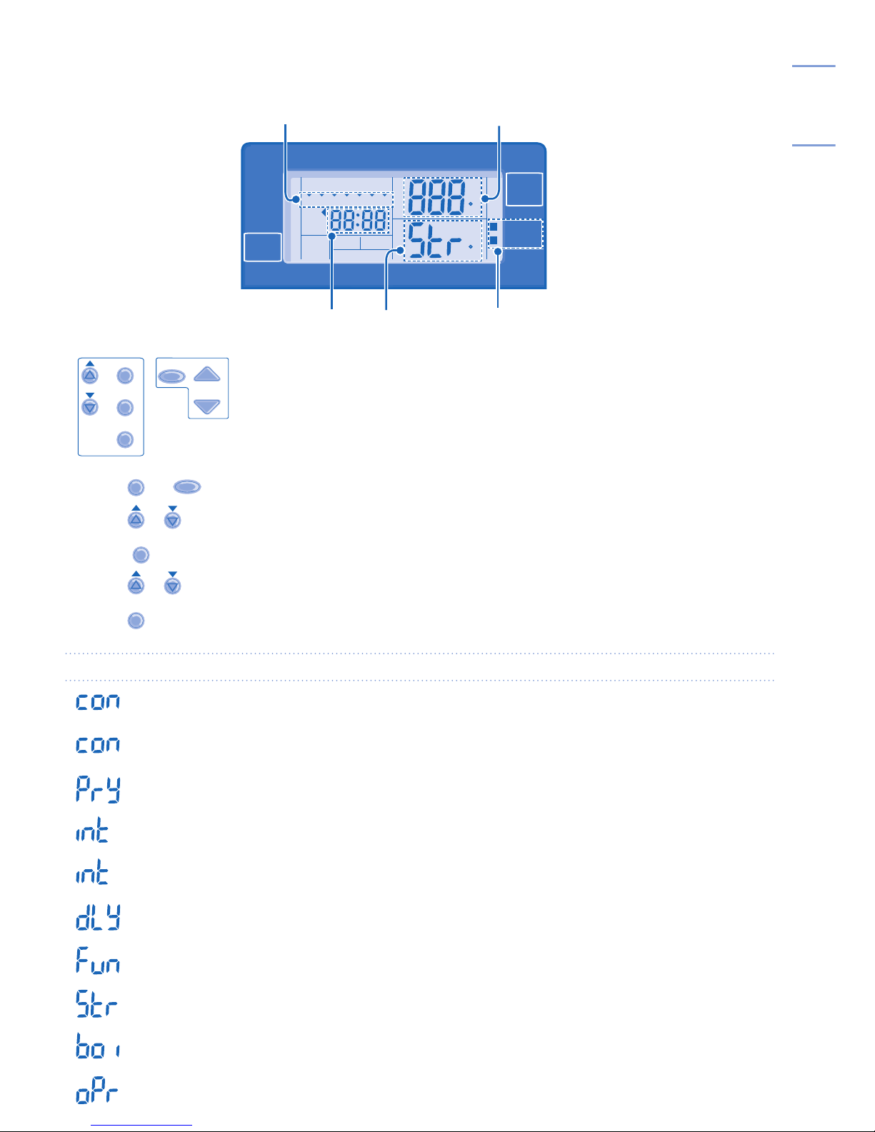
Day display
YES / NO / Temperature display
SETTING / STATUS indicatorFunctions*Timer display
SET
SELECT
CANCEL
SETTING
STATUS
SEARCH
CHECK
SELECT FUNCTIONS AND SET YOUR DESIRED TIMER
1. Press
SET
and
CHECK
simultaneously for 5 seconds to enter special setting mode. “SETTING” and “STATUS” indicator is ON.
2. Press
or to browse functions.
3. Press
SELECT
to enter the function.
4. Press
or to enable YES or disable NO function, or set your desired day and time.
5. Press
SET
to confi rm.
Display Function *
External Thermo Controller (YES / NO)
To set external thermo controller connection.
Tank Connection (YES / NO)
To set tank connection.
Heating Priority (YES / NO)
To choose the heat pump only use for Heating side during HEAT + TANK mode.
Heating Heat-up Interval Set
To set timer for Heating during HEAT + TANK mode (0.5hour ~ 10hours).
Tank Heat-up Interval Set
To set timer for Tank during HEAT + TANK mode (5minutes ~ 1hour 35minutes).
Booster Heater Delay Time Set
To set delay timer for booster heater to ON if tank temperature is not reached (20minutes ~ 1hour 35minutes).
Sterilization (YES / NO)
To set sterilization, if required.
Sterilization Day & Time Set
To set timer for sterilization (only once a week).
Sterilization Temperature Set
To set temperature for sterilization function (40°C ~ 75°C).
Sterilization Continue Time
To set timer to maintain heating temperature in order to complete the sterilization function (5minutes ~ 1hour).
Page 6
6
BASIC OPERATION
OFF
/
ON
TO TURN ON OR OFF THE UNIT
• When unit is ON, operation LED is lit and the actual
temperature for water outlet and outdoor ambient are
shown on the control panel display.
MODE
TO SELECT OPERATION MODE
HEAT HEAT +TANK TANK
• HEAT MODE
- To turn ON or OFF the panel/fl oor heating operation.
- In this mode, the outdoor unit will provide heating
capacity to the indoor unit.
• HEAT + TANK MODE
- In this mode, the outdoor unit will provide heating
capacity to the sanitary tank and indoor unit.
- This operation is not used when the sanitary water
tank is not installed.
• TANK MODE
- To turn ON or OFF the sanitary tank operation.
- In this mode, the outdoor unit will provide heating
capacity to the sanitary tank.
QUIET
TO ENJOY QUIET ENVIRONMENT
• This operation reduces outdoor unit noise. In this
condition, it may cause decrease in heating capacity.
HEATER
BACKUP HEATER OPERATION
• The backup heater provides extra heating capacity
during cold outdoor temperature and only can operated
at heat mode operation for indoor unit.
• The backup heater will automatically turn ON when the
setting conditions is fulfi lled.
• To cancel the Heater operation manually, press the
respective button again.
STATUS
SEARCH
CHECK
SYSTEM STATUS CHECK MODE
1. Press
CHECK
for 5 seconds to enter STATUS mode.
2. Press or to check the Compressor
Running Frequency or Error History.
• Press
CANCEL
to exit STATUS mode.
• Once STATUS mode is entered, “STATUS”
indicator is ON.
• STATUS mode cannot be activated when the
“SETTING” indicator is ON.
• It is strongly recommended to contact the nearest
authorized dealer to change the water temperature
range.
• Using the control panel could set the temperature
range for water outlet temperature and outdoor ambient
temperature.
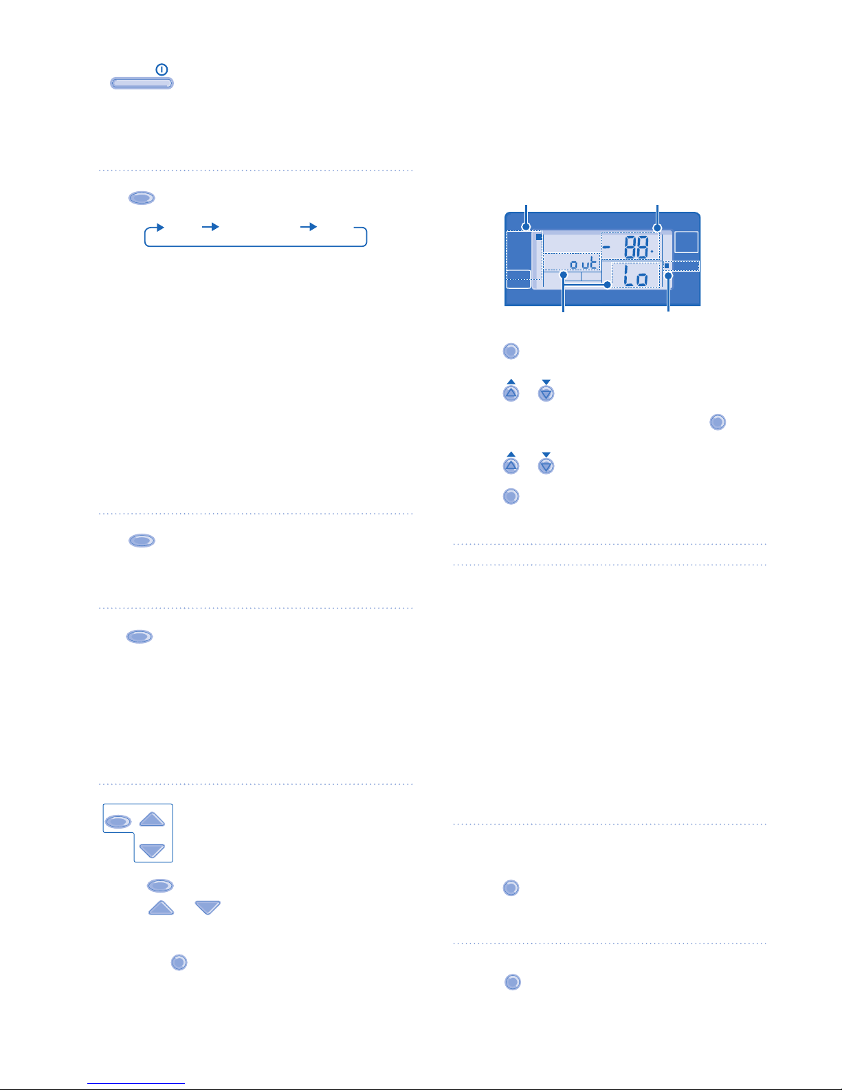
SYSTEM SETTING MODE
TIMER OUTDOOR
HEAT
SETTING
STATUS
PUMPDW
BOOSTER
QUIET
TANK
WATER OUTLET
C
HEATER
OPERATION
FORCE
HEATER
ACTUAL
ON
Operation Mode Temperature display
SETTING indicator
Parameter *
1. Press
SET
for 5 seconds to enter “SETTING” mode.
“SETTING” indicator is ON.
2. Press
or to choose a parameter.
3. After selecting the desired parameter, press
SELECT
to
enter the parameter.
4. Press
or to set the desired temperature.
5. Press
SET
again to confi rm the setting.
• Repeat steps 2 to 5 to set other parameters.
Mode Parameter *
HEAT Outdoor ambient set temperature at low
water outlet temperature (-15°C ~ 15°C).
HEAT Outdoor ambient set temperature at high
water outlet temperature (-15°C ~ 15°C).
HEAT Water outlet set temperature at low outdoor
ambient temperature (25°C ~ 55°C).
HEAT Water outlet set temperature at high outdoor
ambient temperature (25°C ~ 55°C).
HEAT Set temperature for turning OFF heating
operation (5°C ~ 35°C).
HEATER Outdoor ambient set temperature for turning
ON heater operation (-15°C ~ 20°C).
TANK Sanitary tank set temperature
(40°C ~ 75°C).
WATER TEMPERATURE THERMO SHIFT SETTING
Ensure the operation LED is in OFF condition before setting.
1. Press
SET
within 5 seconds.
• Repeat steps 3 to 5 to set the desired shift temperature
(-5°C ~ 5°C).
Notes:
• Press
CANCEL
or wait 30 seconds to exit “SETTING” mode.
• The setting temperature will be stored in the system
once confi rm.
• “SETTING” mode cannot be activated when the
“PUMPDW” and “STATUS” indicator is ON.
ADVANCE OPERATION
Page 7
ENGLISH
7
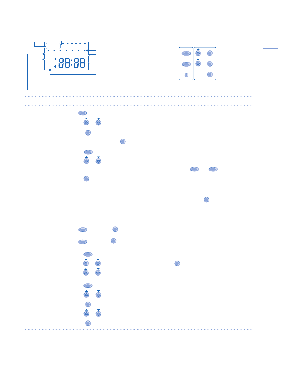
Timer Display
TIMER
1
MON TUEWEDTHU FRI SAT SUN
2 3 4 5 6
ON
OFF
Lights up if Timer
operation is selected
Day to be selected
ON Timer
To automatically switch “ON” the unit
6 different programs can be set in a day (1 ~ 6)
Indicates the selected day
Indicates the next timer operation day
Time to be selected (10 minutes step)
OFF Timer
To automatically switch “OFF” the unit
SET
SELECT
CANCEL
SETTING
CLOCK
OFF/ON
TIMER
Function Step
Enter timer mode
Press
TIMER
.
Set day & time
1.
Press or to select your desired day.
2. Press
SELECT
to confi rm
3. “1” will be blinking, press
SELECT
to set program 1.
4. Press
OFF/ON
to select ON or OFF timer.
5. Press or to select your desired time.
If you want to set the timer together with other operations, press
MODE
and
QUIET
.
6. Press
SET
to confi rm program 1. The selected day will be highlighted with ▼.
• After 2 seconds, the display will move to the next program.
7. Repeat steps 4 to 7 to set programs 2 to 6.
• During timer setup, if no button is pressed within 30 seconds, or if the
SET
button is pressed the
setting at that moment is confi rmed and timer setup is ended.
Add/Modify timer
Repeat the steps above.
Disable timer
Press
TIMER
, then press
CANCEL
.
Enable timer
Press
TIMER
, then press
SET
.
Check timer
1. Press
TIMER
.
2. Press or until your desired day is shown, press
SELECT
to confi rm your selection.
3. Press or to check the set programs.
Cancel timer
1. Press
TIMER
.
2. Press or until your desired day is shown.
3. Press
SELECT
to enter program setting.
4. Press
or until your desired program is shown.
5. Press
CANCEL
to cancel the program.
WEEKLY TIMER SETTING
Notes:
• You can set the Timer for each day of the week (Monday to Sunday) with 6 programs per day.
• ON Timer can be set together with your desired temperature and this temperature will be used continuously.
• Same timer program cannot be set in the same day.
• You may also select collective days with same timer setting.
• Promotes energy saving by allowing you to set up to 6 programs in any given day.
Page 8
0.2
0.40
0.30.1
MPa
TIMER OUTDOOR
HEAT
SETTING
STATUS
PUMPDW
BOOSTER
QUIET
TANK
WATER OUTLET
C
C
OFF
/
ON
HEATER
OPERATION
FORCE
HEATER
ACTUAL
TIMER
1
MONTUEWEDTHUFRI SAT SUN
SOLAR REMOTE
NOT AVAILABLE
23 4 56
ON
OFF
8
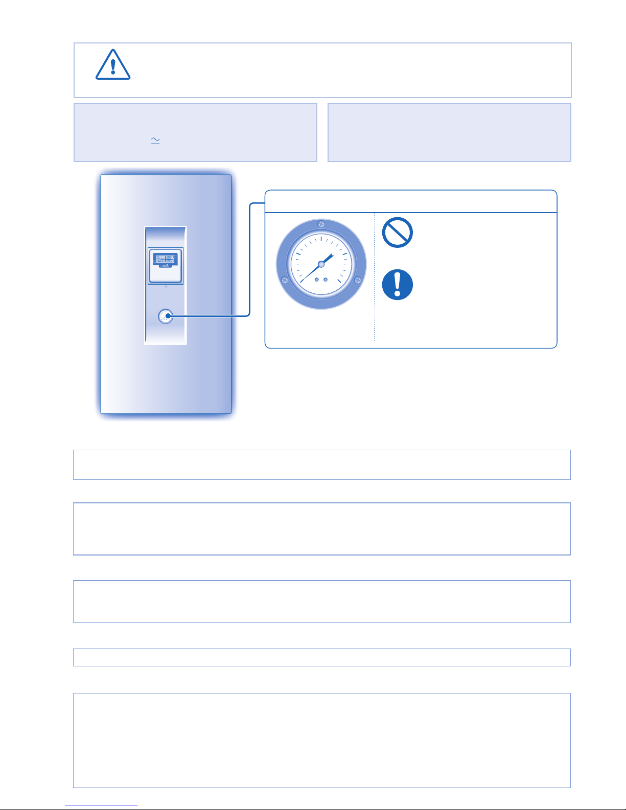
INDOOR UNIT
CAUTION
• Switch off the power supply before cleaning.
WATER PRESSURE GAUGE
WATER PRESSURE GAUGE
0.2
0.40
0.30.1
MPa
• Do not press or hit the glass
cover with hard, pointed
objects. This may damage the
unit.
• Ensure that the water
pressure is between 0.05 to
0.2MPa.
• In case the water pressure is
out of the above range, please
consult authorized dealer.
CLEANING INSTRUCTIONS
CLEANING INSTRUCTIONS
HINT
HINT
• Do not use benzene, thinner or scouring powder.
• Use only soap (
pH7) or neutral household detergent.
• Do not use water hotter than 40°C.
• To ensure optimal performance of the unit, cleaning
maintenance has to be carried out at regular intervals.
Please consult authorized dealer.
INDOOR UNIT & CONTROL PANEL
• Do not splash water directly.
• Wipe the unit gently with a soft, dry cloth.
OUTDOOR UNIT
• Do not obstruct the air inlet and air outlet vents, it may cause low performance or breakdown. Please remove obstacles to
assure the ventilation.
• During winter, please clean and remove the snow near outdoor unit so that the snow does no cover the air inlet and air
outlet vents.
INSPECTION
• In order to ensure optimal performance of the unit, seasonal inspections on the unit and fi eld wiring have to be carried out
at regular intervals. This maintenance should be carried out by authorized dealer.
• Clear any obstruction at the air inlet and air outlet vents of outdoor unit.
FOR EXTENDED NON-USE
• Turn off the power supply.
NON SERVICEABLE CRITERIAS
NON SERVICEABLE CRITERIAS
TURN OFF POWER SUPPLY then please consult authorized dealer under the following conditions:
• Abnormal noise during operation.
• Water/foreign particles have entered the control panel.
• Water leaks from Indoor unit.
• Circuit breaker switches off frequently.
• Power cord becomes unnaturally warm.
Page 9
ENGLISH
9
TROUBLESHOOTING
The following symptoms do not indicate malfunction.
The following symptoms do not indicate malfunction.
SYMPTOM
SYMPTOM
CAUSE
CAUSE
Flowing sound during operation. ► • Refrigerant fl ow inside the unit.
Operation is delayed a few minutes after restart. ► • The delay is a protection to the unit’s compressor.
Outdoor unit emits water/steam. ► • Condensation or evaporation occurs on pipes.
Outdoor unit emits steam during heating mode. ► • This is due to defrost operation happens at the heat
exchanger.
Outdoor unit does not operate. ► • When the outdoor temperature is out of the operation
condition range, the heatpump system enter protection
control.
System diffi cult to heat-up. ► • When heating is operated by indoor unit together with
fl oor heating or panel heater simultaneously, there
may be case where warm water temperature is getting
lower and cause fl oor heating or panel heater heat-up is
weaken.
• When outdoor air temperature is low, it may be diffi cult to
get warm.
• Is the snow pile blocking the discharge outlet or intake
inlet of outdoor unit.
• When water outlet set temperature is low, it may be
diffi cult to get warm.
System cannot get warm instantly. ► • Due to the nature of the heatpump system, it may take
some time to heat-up the water if the unit is operated
from cold-start.
Operation starts after power resumes. ► • Unit is operates under auto restart function.
Check the following before calling for servicing.
Check the following before calling for servicing.
SYMPTOM
SYMPTOM
CHECK
CHECK
Heating operation is not working effi ciently. ► • Set the temperature correctly.
• Is the panel heater valve closed.
• Clear any obstruction at the air inlet and air outlet vents
of outdoor unit.
Noisy during operation. ► • Check if the unit has been installed at an incline or the
cover is not closed properly.
The unit does not work. ► • Check if the circuit breaker is tripped.
Operation LED is no lit or control panel display
is blank.
► • Is the power supply off or power failure.
The operation LED blinks and error code appear on control panel display.
The operation LED blinks and error code appear on control panel display.
TIMER
TIMER
1
MON TUEWEDTHU FRI SAT SUN
2 3 4 5 6
ON
OFF
• Turn the unit off and reveal the error code to authorized dealer.
• Timer operation cancel when error code occur.
Force Heater Mode Button
Force Heater Mode Button
FORCE
• In case of a failure of the Air-to-Water Heatpump system, the backup heater can be used to heat
up the heating water. Press
FORCE
to switch on the backup heater.
• Press
OFF
/
ON
to stop the force heater operation.
• During Force Heater mode, all other operations are not allowed.
Page 10
10
• Ce manuel décrit comment utiliser le système de pompe à chaleur
entre les unités intérieure et extérieure seulement.
• Pour le fonctionnement d’autres systèmes tels que le réservoir d’eau,
le radiateur, le contrôleur thermique externe et le chauffage au sol,
référez-vous aux modes d’emploi de leurs fabricants respectifs.
CONSIGNES DE SÉCURITÉ
TABLE DES MATIÈRES
TABLE DES MATIÈRES
CONSIGNES DE SÉCURITÉ
10~11
PANNEAU DE COMMANDE
12~15
UNITÉ INTÉRIEURE
16
DÉPANNAGE
17
INFORMATIONS
34~35
REMARQUE
REMARQUE
Les illustrations de ce mode d’emploi
sont fournies à titre d’exemple
uniquement et peuvent présenter des
différences par rapport à l’appareil
proprement dit. Celui-ci peut être
modifi é sans préavis à des fi ns
d’amélioration.
CONDITION D’UTILISATION
CONDITION D’UTILISATION
Température de
sortie d’eau (°C)
Unité
intérieure
CHAUFFAGE
Max. 55
Min. 25
Température
ambiante (°C)
Unité
extérieure
CHAUFFAGE
Max. 35
Min. -20
ATTENTION: Si la température extérieure sort
de la plage de températures
ci-dessus, la capacité thermique
chutera de façon importante et
il se peut que l’unité extérieure
s’arrête pour le contrôle de
protection.
Pour éviter des blessures corporelles sur vous-même et sur les autres ou
des dégâts matériels, respectez les instructions ci-dessous.
Tout dysfonctionnement dû au non-respect des instructions peut
occasionner des nuisances ou des dégâts dont la gravité est classée
comme décrit ci-après:
AVERTISSEMENT
AVERTISSEMENT
Ce symbole signale la présence d’un
danger pouvant provoquer des blessures
graves ou mortelles.
ATTENTION
ATTENTION
Ce symbole signale la présence d’un
danger pouvant provoquer des blessures
corporelles ou des dégâts matériels.
Les instructions à respecter sont classées d’après les symboles suivants:
Ce symbole désigne une action
INTERDITE.
Ces symboles désignent des
actions OBLIGATOIRES.
AVERTISSEMENT
AVERTISSEMENT
UNITÉ INTÉRIEURE ET UNITÉ EXTÉRIEURE
UNITÉ INTÉRIEURE ET UNITÉ EXTÉRIEURE
Cet appareil n’est pas conçu pour être utilisé par des personnes
(y compris les enfants) aux capacités physiques, sensorielles
ou mentales diminuées, ou manquant d’expérience ou de
connaissances, sauf si une personne responsable de leur
sécurité leur a expliqué le fonctionnement de l’appareil et les
garde sous surveillance. Les enfants doivent être supervisés afi n
qu’ils ne jouent pas avec l’appareil.
Veuillez consulter un revendeur agréé ou un spécialiste pour la
réparation, l’installation, le retrait ou le déménagement de l’unité.
Une installation et une manipulation incorrectes pourraient
occasionner des fuites, un choc électrique ou un incendie.
N’installez pas l’appareil dans une atmosphère potentiellement
explosive ou infl ammable. Sinon, il y a un risque d’incendie.
N’insérez jamais vos doigts ou des objets dans
l’unité intérieure ou extérieure du climatiseur, les
parties tournantes peuvent causer des blessures.
Ne touchez pas l’unité extérieure au cours d’un orage, cela
pourrait provoquer un choc électrique.
N’essayez pas de réparer l’appareil vous-même. Vous
pourriez vous blesser en cas de mauvaise manipulation.
N’installez pas l’unité intérieure à l’extérieur. Elle est
uniquement conçue pour une installation en intérieur.
Page 11
FRANÇAIS
11
ATTENTION
ATTENTION
UNITÉ INTÉRIEURE ET UNITÉ EXTÉRIEURE
UNITÉ INTÉRIEURE ET UNITÉ EXTÉRIEURE
Ne nettoyez pas l’unité intérieure avec de l’eau,
du benzène, du solvant ou de la poudre à récurer.
N’installez pas l’unité à proximité d’un
équipement combustible ou dans une salle de
bains. Sinon, il y a risque de choc électrique ou
d’incendie.
Ne touchez pas le tuyau d’évacuation d’eau de
l’unité intérieure pendant le fonctionnement.
Ne posez rien sur ou sous l’unité.
Ne vous asseyez pas et ne montez
pas sur l’unité, vous risquez de
tomber accidentellement.
Ne touchez pas l’ailette pointue
d’aluminium, les parties pointues
peuvent causer des dommages.
Assurez-vous que le tuyau de vidange est
correctement raccordé. Sinon, une fuite peut
se produire.
Vérifi ez régulièrement le rack d’installation pour
vous assurer qu’il n’est pas endommagé. Après
de longues périodes d’utilisation, la solidité du
rack d’installation peut être amoindrie.
PANNEAU DE COMMANDE
Ne laissez pas le panneau de commande
prendre l’humidité. Sinon, il y a risque de choc
électrique ou d’incendie.
N’appuyez pas sur les touches du panneau de
commande à l’aide d’objets durs et pointus.
Vous pourriez endommager l’unité.
Ne nettoyez pas le panneau de commande
avec de l’eau, du benzène, du diluant ou de la
poudre à récurer.
N’inspectez pas et n’entretenez pas le panneau
de commande vous-même. Consultez un
revendeur agréé. Sinon, vous pourriez vous
blesser en cas de mauvaise manipulation.
AVERTISSEMENT
AVERTISSEMENT
ALIMENTATION
N’utilisez pas de cordon modifi é,
de raccords, de rallonge ou de
cordon non spécifi é afi n d’éviter
une surchauffe et un incendie.
Ne partagez pas la même prise d’alimentation
qu’un autre équipement afi n d’éviter une
surchauffe et un incendie.
N’utilisez pas l’appareil pas avec les mains
mouillées afi n d’éviter un choc électrique.
Si le cordon d’alimentation est endommagé, il doit
être remplacé par le fabriquant, par un de ses
techniciens ou par une personne qui possède des
qualifi cations équivalentes afi n d’éviter tout risque.
Cette unité est équipée d’un disjoncteur de
courant résiduel (RCCB). Il est fortement conseillé
de faire contrôler le fonctionnement du RCCB
après l’installation et périodiquement après
l’entretien ou la maintenance par un revendeur
agréé afi n de garantir son bon fonctionnement.
Sinon, il y a risque de choc électrique ou
d’incendie en cas de dysfonctionnement.
Il est conseillé de porter des gants pendant la
maintenance ou l’entretien afi n d’éviter tout risque.
Cet équipement doit être raccordé à la terre afi n
d’éviter un choc électrique ou un incendie.
En cas d’urgence ou dans des conditions anormales
(odeur de brulé, etc.), débranchez l’alimentation
électrique et contactez le revendeur autorisé.
Prévenez les chocs électriques coupant
l’alimentation:
- Avant le nettoyage ou l’entretien.
- En cas de non-utilisation prolongée.
- En cas d’activité orageuse anormalement forte.
Cet appareil convient à de multiples usages.
Tous les circuits d’alimentation électrique doivent
être coupés avant toute intervention sur les
bornes de l’unité intérieure, afi n d’éviter tout choc
électrique, brûlure ou blessure mortelle.
/
/
Chauffage au sol
Panneau
Panneau de commande
Alimentation
Réservoir d’eau
Unité Intérieure
Unité Extérieure
Page 12

12
PANNEAU DE COMMANDE
• Il est possible que certaines fonctions décrites dans ce manuel ne soient pas applicables à votre unité.
• Consultez votre revendeur agréé le plus proche pour en savoir plus.
• En fonctionnement normal, les touches
ERROR
RESET
,
FORCE
et
PUMPDW
sont inactives.
1
Touche de marche/arrêt (OFF/ON)
14
Voyant de MARCHE/ARRÊT du mode silencieux
2
DEL de fonctionnement
15
Voyant de MARCHE/ARRÊT de la demande de chauffage
de secours
3
Touche de mode de fonctionnement
16
Voyant de MARCHE/ARRÊT de la demande de
chauffage forcé
4
Touche de fonctionnement silencieux
17
Voyant de MARCHE/ARRÊT de fonctionnement effectif
du chauffage de secours
5
Touche de fonctionnement du chauffage de
secours de l’unité intérieure
18
Voyant de MARCHE/ARRÊT de fonctionnement effectif
du chauffage de démarrage
6
Touches de mode de réglage du système
19
Voyant de MARCHE/ARRÊT du mode de réglage du
système
7
Touche de groupe de réglage de la minuterie
20
Voyant de MARCHE/ARRÊT du mode de contrôle de
l’état du système
8
Touche de mode de chauffage forcé
21
Voyant de MARCHE/ARRÊT du mode de pumpdown du
système
9
Touche de mode d’évacuation du système
22
Affi chage du réglage Horloge/Minuterie
10
Touches de mode de contrôle de l’état du système
23
Affi chage à distance
11
Touche de réinitialisation d’erreur
24
Affi chage de la température ambiante extérieure
12
Voyant de MARCHE/ARRÊT du mode chauffage
25
Affi chage de la température de sortie d’eau
13
Voyant de MARCHE/ARRÊT du mode réservoir
Remarques:
• Le jour et l’heure doivent être réglés:
- Au premier démarrage de l’unité.
- Au redémarrage de l’unité après une longue période
d’arrêt.
• L’heure réglée sera l’heure standard pour toutes les
opérations de la minuterie.
1. Appuyez sur
CLOCK
.
2. Appuyez sur
ou pour régler le jour.
3. Appuyez sur
SET
pour confi rmer.
4. Répétez les étapes 2 et 3 pour régler l’heure.
PRÉPARATION DU PANNEAU DE COMMANDE
Réglage du jour et de l’heure
TIMER OUTDOOR
HEAT
SETTING
STATUS
PUMPDW
BOOSTER
QUIET
TANK
WATER OUTLET
C
C
SET
SELECT
CANCEL
ERROR
RESET
SETTING
STATUS
SEARCH
PUMPDWFORCECLOCK
CHECK
OFF
/
ON
MODE
HEATER
QUIET
OFF/ON
TIMER
HEATER
OPERATION
FORCE
HEATER
ACTUAL
TIMER
1
MON TUEWEDTHU FRI SAT SUN
REMOTE
2 3 4 56
ON
OFF
16
1
22
21
10
17
18
19
20
24
9
5
25
3
8
4
7
2
15
14
12
13
6 11
23
Page 13

FRANÇAIS
13
CONFIGURATION DES FONCTIONS SPÉCIALES
CONFIGURATION DES FONCTIONS SPÉCIALES
• Après l’installation initiale, vous pouvez ajuster les réglages manuellement. Le réglage initial reste actif jusqu’à sa modifi cation par l’utilisateur.
• Le panneau de contrôle peut être utilisé pour plusieurs installations. Il est possible que certaines fonctions ne soient pas applicables à votre unité.
TIMER OUTDOOR
HEAT
SETTING
STATUS
PUMPDW
BOOSTER
QUIET
TANK
WATER OUTLET
C
C
HEATER
OPERATION
FORCE
HEATER
ACTUAL
MON TUE WEDTHU FRI SAT SUN
REMOTE
ON
Affi chage du jour
OUI / NON / Affi chage de la température
Voyant de RÉGLAGE / ÉTATFonction*Affi chage de la
minuterie
SET
SELECT
CANCEL
SETTING
STATUS
SEARCH
CHECK
1. Appuyez simultanément sur
SET
et
CHECK
pendant 5 secondes pour entrer en mode de réglage spécial. Le voyant
« RÉGLAGE » et « ÉTAT » est ACTIVÉ.
2. Appuyez sur
ou pour naviguer entre les fonctions.
3. Appuyez sur
SELECT
pour entrer dans la fonction.
4.
Appuyez sur
ou
pour activer la fonction OUI ou désactiver la fonction NON, ou réglez la date et l’heure de votre choix.
5. Appuyez sur
SET
pour confi rmer.
Affi chage Fonction *
Contrôleur thermique externe (OUI / NON)
Pour défi nir une connexion avec le contrôleur thermique externe.
Connexion du réservoir (OUI / NON)
Pour défi nir une connexion avec le réservoir.
Priorité chauffage (OUI / NON)
Pour choisir la pompe à chaleur uniquement pour le côté chauffage en mode CHAUFFAGE + RÉSERVOIR.
Réglage de l’intervalle de chauffe du chauffage
Pour régler le minuteur du chauffage en mode CHAUFFAGE + RÉSERVOIR (0,5 heure ~ 10 heures).
Réglage de l’intervalle de chauffe du réservoir
Pour régler le minuteur du réservoir en mode CHAUFFAGE + RÉSERVOIR (0,5 minute ~ 1 heure 35 minutes).
Réglage de l’heure de retard du chauffage de démarrage
Pour régler la minuterie de retard du chauffage de démarrage en position de marche (ON) si la température du
réservoir n’est pas atteinte (20 minutes ~ 1 heure 35 minutes).
Stérilisation (OUI / NON)
Pour régler la stérilisation, si nécessaire.
Défi nition du jour et de l’heure de la stérilisation
Pour régler le minuteur pour la stérilisation (une fois par semaine seulement).
Réglage de la température de stérilisation
Pour régler la température pour la fonction de stérilisation (40°C ~ 75°C).
Temps continu de stérilisation
Pour régler le minuteur de façon à maintenir la température de chauffage afi n de terminer la fonction de
stérilisation (5 minutes ~ 1 heure).
SÉLECTIONNEZ LES FONCTIONS ET RÉGLEZ
LE MINUTEUR À VOTRE CONVENANCE
Page 14

14
FONCTIONNEMENT DE BASE
OFF
/
ON
POUR METTRE L’APPAREIL
SOUS/ HORS TENSION
• Lorsque l’unité est en marche (ON), le voyant LED de
fonctionnement est éclairé et les températures réelles
de sortie d’eau et d’air extérieur apparaissent sur
l’affi cheur du panneau de commande.
MODE
POUR SÉLECTIONNER UN MODE
DE FONCTIONNEMENT
HEAT HEAT +TANK TANK
• MODE CHAUFFAGE
- Pour ACTIVER ou DÉSACTIVER le mode de
chauffage de panneau / au sol.
- Dans ce mode, l’unité extérieure fournit la capacité
de chauffage à l’unité intérieure.
• MODE CHAUFFAGE + RÉSERVOIR
-
Dans ce mode, l’unité extérieure fournit la capacité de
chauffage au réservoir sanitaire et à l’unité intérieure.
- Cette opération n’est pas utilisée si le réservoir d’eau
sanitaire n’est pas installé.
• MODE RÉSERVOIR
- Pour ACTIVER ou DÉSACTIVER le fonctionnement
du réservoir sanitaire.
- Dans ce mode, l’unité extérieure fournit la capacité
de chauffage au réservoir sanitaire.
QUIET
POUR UN ENVIRONNEMENT
SILENCIEUX
• Cette opération réduit le bruit de l’unité extérieure.
Dans cette condition, cela peut provoquer une baisse
de la capacité de chauffage.
HEATER
OPÉRATION DE CHAUFFAGE DE
SECOURS
• Le chauffage de secours fournit une capacité de
chauffage supplémentaire en cas de température
extérieure très basse et ne peut être utilisé que lorsque
l’unité intérieure est en mode chauffage.
• Le chauffage de secours est automatiquement ACTIVÉ
lorsque les conditions de réglage sont remplies.
• Pour annuler manuellement l’opération de chauffage,
appuyez à nouveau sur la touche correspondante.
STATUS
SEARCH
CHECK
MODE DE CONTRÔLE DE
L’ÉTAT DU SYSTÈME
1.
Appuyez sur
CHECK
pendant 5 secondes pour entrer en
mode de statut (STATUS).
2.
Appuyez sur ou pour contrôler la fréquence
de démarrage du compresseur ou l’historique des erreurs.
• Appuyez sur
CANCEL
pour sortir du mode de STATUT.
• Une fois le mode de statut (STATUS) activé, le
voyant « STATUS » s’allume.
• Le mode de statut (STATUS) ne peut pas être
activé lorsque le voyant « STATUS » est allumé.
• Il est vivement recommandé de contacter le revendeur
agréé le plus proche pour changer la plage de
température de l’eau.
• Il est possible d’utiliser le panneau de commande pour
régler la plage de température de sortie d’eau et de
température d’air extérieur.
MODE DE RÉGLAGE DU SYSTÈME
TIMER OUTDOOR
HEAT
SETTING
STATUS
PUMPDW
BOOSTER
QUIET
TANK
WATER OUTLET
C
HEATER
OPERATION
FORCE
HEATER
ACTUAL
ON
Mode de fonctionnement Affi chage de la température
Indicateur de réglage (SETTING)
Paramètre *
1.
Appuyez sur
SET
pendant 5 secondes pour entrer en mode
de réglage (SETTING). Le voyant « SETTING » s’allume.
2.
Appuyez sur
ou sur pour choisir un paramètre.
3. Après avoir sélectionné le paramètre désiré, appuyez
sur
SELECT
pour entrer le paramètre.
4. Appuyez sur ou sur pour défi nir la température
désirée.
5. Appuyez à nouveau sur
SET
pour confi rmer le réglage.
•
Répétez les étapes 2 à 5 pour défi nir les autres
paramètres.
Mode Paramètre*
HEAT
Température de l’air extérieur défi nie pour une
température de sortie d’eau basse (-15°C ~ 15°C).
HEAT
Température de l’air extérieur défi nie pour une
température de sortie d’eau élevée (-15°C ~ 15°C).
HEAT
Température de sortie d’eau défi nie pour une
température de l’air extérieur basse (25°C ~ 55°C).
HEAT
Température de sortie d’eau défi nie pour une
température de l’air extérieur élevée (25°C ~ 55°C).
HEAT
Température défi nie pour l’arrêt (OFF) de l’opération de
chauffage (5°C ~ 35°C).
HEATER
Température de l’air extérieur défi nie pour le démarrage
(ON) de l’opération de chauffage (-15°C ~ 20°C).
TAN K
Température du réservoir sanitaire défi nie
(40°C ~ 75°C).
RÉGLAGE DU RELAIS THERMIQUE DE LA TEMPÉRATURE DE L’EAU
Assurez-vous que le voyant LED de fonctionnement est éteint
(OFF) avant de réaliser le réglage.
1.
Appuyez sur
SET
dans les 5 secondes.
• Répétez les étapes 3 à 5 pour régler la température de
relais souhaitée (-5°C ~ 5°C).
Remarques:
• Appuyez sur
CANCEL
ou attendez 30 secondes pour quitter
le mode de réglage (SETTING).
• La température de réglage est mémorisée dans le
système sur confi rmation.
• Le mode « SETTING » ne peut pas être activé lorsque
les voyants « PUMPDW » et « STATUS » sont allumés.
FONCTIONNEMENT AVANCÉ
Page 15

FRANÇAIS
15
Affi chage de la minuterie
TIMER
1
MON TUEWEDTHU FRI SAT SUN
2 3 4 5 6
ON
OFF
S’illumine lorsque l’opération
de minuterie est sélectionnée
Jour à sélectionner
Minuterie de démarrage (ON)
Pour démarrer automatiquement l’unité
6 programmes différents peuvent être défi nis
dans une journée (1 ~ 6)
Indique le jour sélectionné
Indique le fonctionnement de la minuterie du
jour suivant
Heure à sélectionner
(incréments de 10 minutes)
Minuterie d’arrêt (OFF)
Pour arrêter automatiquement l’unité
SET
SELECT
CANCEL
SETTING
CLOCK
OFF/ON
TIMER
Fonction Étape
Entrer en mode de
minuterie
Appuyez sur
TIMER
.
Régler le jour et
l’heure
1.
Appuyez sur ou pour sélectionner le jour de votre choix.
2. Appuyez sur
SELECT
pour confi rmer.
3. “1” clignotera, appuyez sur
SELECT
pour régler le programme 1.
4. Appuyez sur
OFF/ON
pour sélectionner la minuterie de DÉMARRAGE ou d’ARRÊT.
5. Appuyez sur ou pour sélectionner l’heure de votre choix.
Si vous souhaitez régler le minuteur en même temps que d’autres opérations, appuyez sur
MODE
et
QUIET
.
6. Appuyez sur
SET
pour confi rmer le programme 1. Le jour sélectionné sera mis en évidence avec ▼.
• Après 2 secondes, l’affi chage se déplacera au programme suivant.
7. Répétez les étapes 4 à 7 pour régler les programmes 2 à 6.
•
Au cours de la confi guration de la minuterie, si aucune touche n’est pressée dans les 30 secondes ou si la touche
SET
est pressé, le réglage à ce moment-là, est confi rmé et la confi guration de la minuterie est terminée.
Ajouter/modifi er
une minuterie
Répétez les étapes ci-dessus.
Désactiver la
minuterie
Appuyez sur
TIMER
, puis appuyez sur
CANCEL
.
Activer la
minuterie
Appuyez sur
TIMER
, puis appuyez sur
SET
.
Vérifi er la
minuterie
1. Appuyez sur
TIMER
.
2. Appuyez sur ou jusqu’à ce que votre jour souhaité s’affi che, appuyez sur
SELECT
pour confi rmer
votre sélection.
3. Appuyez sur ou pour vérifi er les programmes réglés.
Annuler la
minuterie
1. Appuyez sur
TIMER
.
2. Appuyez sur ou jusqu’à ce que votre jour souhaité s’affi che.
3. Appuyez sur
SELECT
pour entrer dans le réglage des programmes.
4. Appuyez sur ou jusqu’à ce que votre programme souhaité s’affi che.
5. Appuyez sur
CANCEL
pour annuler le programme.
RÉGLAGE DE LA MINUTERIE HEBDOMADAIRE
Remarques:
• Vous pouvez régler la minuterie pour chaque jour de la semaine (du lundi au dimanche), avec 6 programmes par jour.
• La minuterie de démarrage (ON) peut être réglée en même temps que votre température désirée et cette température sera
utilisée continuellement.
• Le même programme de minuterie ne peut pas être réglé dans la même journée.
• Vous pouvez également sélectionner des groupes de jours avec le même réglage de minuterie.
• Favorise les économies d’énergie en vous permettant de régler jusqu’à 6 programmes tous les jours.
Page 16

0.2
0.40
0.30.1
MPa
TIMER OUTDOOR
HEAT
SETTING
STATUS
PUMPDW
BOOSTER
QUIET
TANK
WATER OUTLET
C
C
OFF
/
ON
HEATER
OPERATION
FORCE
HEATER
ACTUAL
TIMER
1
MONTUEWEDTHUFRI SAT SUN
SOLAR REMOTE
NOT AVAILABLE
23 4 56
ON
OFF
16
UNITÉ INTÉRIEURE
ATTENTION
• Coupez l’alimentation avant le nettoyage.
JAUGE DE PRESSION D’EAU
JAUGE DE PRESSION D’EAU
0.2
0.40
0.30.1
MPa
•
Ne faites pas subir de pression ou
de coups au couvercle en verre
avec des objets durs et pointus.
Cela pourrait endommager l’unité.
• Assurez-vous que la pression de
l’eau est située entre 0,05 et 0,2
MPa.
• Si la pression de l’eau sort de
la plage ci-dessus, veuillez
consulter votre revendeur agréé.
CONSIGNES POUR LE NETTOYAGE
CONSIGNES POUR LE NETTOYAGE
CONSEIL
CONSEIL
• N’utilisez pas de benzène, de diluant ou de poudre à
récurer.
• Utilisez uniquement du savon (
pH7) ou un détergent
ménager neutre.
• N’utilisez pas de l’eau dont la température est
supérieure à 40°C.
• Pour garantir une performance optimale de l’unité, un
nettoyage d’entretien doit être effectué à intervalles
réguliers. Veuillez consulter un revendeur agréé.
UNITÉ ET PANNEAU DE COMMANDE INTÉRIEURS
• N’éclaboussez pas d’eau directement.
• Essuyez délicatement l’unité avec un chiffon doux et sec.
UNITÉ EXTÉRIEURE
• N’obstruez pas les évents d’admission et de sortie d’air sous peine de provoquer une baisse des performances ou une
panne. Retirez les obstacles pour garantir la ventilation.
• En hiver, nettoyez et retirez la neige à proximité de l’unité extérieure de façon à ce qu’elle n’obstrue pas les évents
d’admission et de sortie d’air.
INSPECTION
• Pour garantir une performance optimale de l’unité, des inspections périodiques de l’unité et du câblage doivent être
effectuées à intervalles réguliers. Cette maintenance doit être effectuée par le revendeur agréé.
• Dégagez toute obstruction des évents d’admission et de sortie d’air de l’unité extérieure.
PRÉPARATION EN CAS D’INUTILISATION PROLONGÉE
• Déconnectez la source d’alimentation.
PIECES NON SUSCEPTIBLES D’ETRE REPAREES PAR VOS SOINS
PIECES NON SUSCEPTIBLES D’ETRE REPAREES PAR VOS SOINS
DÉBRANCHEZ L’ALIMENTATION ÉLECTRIQUE et contactez le revendeur autorisé dans les conditions suivantes:
• Bruits anormaux pendant la mise en service.
• Pénétration d’eau/corps étrangers à l’intérieur du panneau de commande.
• Fuite d’eau de l’unité intérieure.
• Désactivation fréquente du disjoncteur.
• Le cordon d’alimentation est inhabituellement chaud.
Page 17

FRANÇAIS
17
DÉPANNAGE
Les hénomènes suivants ne correspondent pas à un dysfonctionnement.
Les hénomènes suivants ne correspondent pas à un dysfonctionnement.
PHÉNOMÈNE
PHÉNOMÈNE
CAUSE
CAUSE
Bruit d’écoulement pendant le fonctionnement. ► • Fluide frigorigène à l’intérieur de l’appareil.
Le fonctionnement ralentit quelques minutes après avoir
remis en marche l’appareil.
► • Le ralentissement est une protection du compresseur de
l’appareil.
L’unité extérieure dégage de la vapeur ou de l’eau. ► • De l’eau se condense ou s’évapore dans les tuyaux.
En mode de chauffage, l’unité extérieure émet de la
vapeur.
► • Cela est dû à l’opération de dégivrage sur l’échangeur
thermique.
L’unité extérieure ne fonctionne pas. ► • Lorsque la température extérieure sort de la plage des
conditions de fonctionnement, le système de pompe à
chaleur entre en contrôle de protection.
Le système a du mal à chauffer. ► • Si le chauffage fourni par l’unité intérieure est doublé
d’un chauffage au sol ou d’un radiateur, il se peut que la
température de l’eau chaude baisse et affaiblisse l’action
calorifi que du chauffage au sol ou du radiateur.
• Lorsque la température extérieure est faible, il peut être
diffi cile de chauffer.
• Vérifi er qu’aucun bloc de neige n’obstrue l’évacuation ou
l’admission de l’unité extérieure.
• Si la température de sortie d’eau est faible, il peut être
diffi cile d’obtenir de la chaleur.
Le système ne peut pas chauffer instantanément. ► • De par la nature du système de pompe à chaleur, la
chauffe de l’eau peut prendre un certain temps si l’unité
est démarrée à froid.
Le fonctionnement démarre après le rétablissement du
courant.
► • L’unité fonctionne avec la fonction de redémarrage
automatique.
Vérifi ez les éléments suivants avant de faire appel au service de maintenance.
Vérifi ez les éléments suivants avant de faire appel au service de maintenance.
PHÉNOMÈNE
PHÉNOMÈNE
VÉRIFICATION
VÉRIFICATION
La fonction chauffage ne fonctionne pas effi cacement. ► • Réglez la température correctement.
• Vérifi ez que la vanne du panneau chauffant est fermée.
• Dégagez toute obstruction des évents d’admission et de
sortie d’air de l’unité extérieure.
L’appareil fait du bruit lorsqu’il fonctionne. ► • Vérifi ez si l’unité n’a pas été installée en inclinaison ou si
le capot n’est pas mal fermé.
L’appareil ne fonctionne pas. ► • Vérifi ez si le coupe-circuit est déclenché.
La DEL de fonctionnement n’est pas allumée ou l’écran du
panneau de commande est vide.
► • Il se peut que l’alimentation soit coupée ou qu’il y ait une
panne de courant.
La DEL de fonctionnement clignote et un code d’erreur apparaît sur l’écran du panneau de commande.
La DEL de fonctionnement clignote et un code d’erreur apparaît sur l’écran du panneau de commande.
TIMER
TIMER
1
MON TUEWEDTHU FRI SAT SUN
2 3 4 5 6
ON
OFF
• Éteignez l’unité et indiquez le code d’erreur au revendeur agréé.
• L’opération de minuterie est annulée lorsque le code d’erreur apparaît.
Touche de mode de chauffage forcé
Touche de mode de chauffage forcé
FORCE
•
En cas de panne du système de pompe à chaleur air-eau, le chauffage de secours peut être utilisé
pour chauffer l’eau de chauffage. Appuyez sur
FORCE
pour enclencher le chauffage de secours.
• Appuyez sur
OFF
/
ON
pour arrêter l’opération de chauffage forcé.
• En mode de chauffage forcé, toutes les opérations ne sont pas autorisées.
Page 18

18
• Este manual describe cómo operar el sistema de bomba de calor
solamente entre las unidades interior y exterior.
• Para conocer otras operaciones como la del tanque de agua,
radiador, controlador térmico externo y el sistema subterráneo,
consulte los respectivos manuales de funcionamiento del fabricante.
PRECAUCIONES DE SEGURIDAD
CONTENIDO
CONTENIDO
PRECAUCIONES DE
SEGURIDAD
18~19
PANEL DE CONTROL
20~23
UNIDAD INTERIOR
24
LOCALIZACIÓN DE
AVERÍAS
25
INFORMACIÓN
34~35
NOTA
NOTA
Las ilustraciones de este manual
sirven únicamente para describir las
explicaciones y pueden no coincidir
exactamente con las del aparato
suministrado. Están sujetas a cambios
sin previo aviso con el fi n de mejorar el
producto.
CONDICIONES DE
CONDICIONES DE
FUNCIONAMIENTO
FUNCIONAMIENTO
Temperatura de la salida
de agua (°C)
Interior
CALENTAMIENTO
Máx. 55
Mín. 25
Temperatura ambiente
(°C)
Exterior
CALENTAMIENTO
Máx. 35
Mín. -20
AVISO :
Cuando la temperatura exterior
esté fuera del intervalo de
temperatura superior, la capacidad
de calentamiento disminuirá
signifi cativamente y la unidad
exterior podría pararse para
controlar la protección.
Para evitar lesiones personales, lesiones a terceros, o daños materiales,
cumpla lo siguiente.
El uso incorrecto por no seguir las instrucciones puede causar daños o
averías; su gravedad se clasifi ca con las indicaciones siguientes:
ADVERTENCIA
ADVERTENCIA
Esta indicación advierte del posible
peligro de muerte o de daños graves.
PRECAUCIÓN
PRECAUCIÓN
Esta indicación advierte de los posibles
daños o desperfectos materiales.
Las instrucciones que deben seguirse están clasifi cadas mediante los
siguientes símbolos:
Este símbolo denota una acción
que está PROHIBIDA.
Estos símbolos denotan acciones
que son OBLIGATORIAS.
ADVERTENCIA
ADVERTENCIA
UNIDAD INTERIOR Y UNIDAD EXTERIOR
UNIDAD INTERIOR Y UNIDAD EXTERIOR
Este aparato no debe ser utilizado por personas (incluyendo
niños) con discapacidades mentales, sensoriales o físicas,
o falta de experiencia y conocimiento, a menos que hayan
recibido formación o supervisión en relación al uso del
aparato por una persona responsable por su seguridad. Los
niños deberían estar supervisados para asegurar que no
juegan con el aparato.
Consulte a un distribuidor autorizado o especialista para
reparar, instalar, retirar y reinstalar la unidad. Una instalación
y uso incorrectos provocarán fugas, descargas eléctricas o
incendios.
No instale la unidad en ambientes potencialmente
explosivos o infl amables. En caso contrario, podría provocar
accidentes de incendios.
No introduzca los dedos u otros objetos en la unidad
exterior o interior del aire acondicionado, ya que las
partes rotatorias podrían provocarle lesiones.
No toque la unidad exterior durante un relámpago, ya que
podría causar una descarga eléctrica.
No intente reparar la unidad usted mismo. De lo contrario,
podría causar lesiones si se manipula mal.
No instale la unidad interior en exteriores. Está diseñada
sólo para el uso en interiores.
Page 19

19
ESPAÑOL
/
/
PRECAUCIÓN
PRECAUCIÓN
UNIDAD INTERIOR Y UNIDAD EXTERIOR
No limpie la unidad interior con agua, benceno,
disolvente o limpiador en polvo.
No instale la unidad cerca de ningún equipo
combustible ni en un baño. De lo contrario,
podría causar una descarga eléctrica o incendio.
No toque la tubería de descarga de agua en la
unidad interior durante la operación.
No coloque nada arriba ni abajo de la unidad.
No se siente o pare sobre la unidad,
se podría caer accidentalmente.
No tocar las partes de aluminio
angulosas, pueden causar daños.
Asegúrese de que el tubo de drenaje esté
conectado correctamente. Si no es así, se
podrían producir fugas.
Revise periódicamente el bastidor de
instalación para asegurarse de que no esté
dañado. Luego de períodos prolongados de
uso, es posible que se haya deteriorado la
fuerza del bastidor de instalación.
PANEL DE CONTROL
No permita que el panel de control se
humedezca. De lo contrario, podría causar una
descarga eléctrica o incendio.
No presione los botones del panel de control
con objetos duros y puntiagudos. De lo
contrario, podría dañar la unidad.
No lave el panel de control con agua, benceno,
disolvente o limpiador en polvo.
No inspeccione ni repare el panel de control
usted mismo. Consulte con un distribuidor
autorizado. De lo contrario, podría causar
lesiones si se manipula mal.
ADVERTENCIA
ADVERTENCIA
FUENTE DE ENERGÍA
No utilice un cable modifi cado,
unido con otro, un cable
de extensión o un cable
no especifi cado para evitar
sobrecalentamiento e
incendios.
No comparta la misma salida eléctrica con otros
equipos para evitar el calentamiento e incendios.
No lo use con las manos mojadas para evitar
descargas eléctricas.
Para evitar riesgos, si el cable de alimentación
está dañado y es necesario cambiarlo, deberá
hacerlo el fabricante, un representante del
servicio técnico o una persona cualifi cada.
Esta unidad está equipada con un interruptor
por corriente residual (RCCB). Se recomienda
verifi car el funcionamiento del RCCB después de
la instalación y periódicamente después de que
el distribuidor autorizado realizó reparaciones o
el mantenimiento para asegurarse de que esté
funcionando en buenas condiciones. De otra
manera, en caso de un fallo, pueden producirse
peligrosas descargas eléctricas o incendios.
Se recomienda usar guantes durante la
reparación o mantenimiento para evitar riesgos.
Este equipo deberá conectarse a tierra para
evitar descargas eléctricas o incendios.
En caso de emergencia o condiciones anormales
(olor a quemado, etc.), corte la alimentación de
energía y consulte al distribuidor autorizado.
Evite descargas eléctricas desconectando la
alimentación eléctrica cuando:
- Antes de limpiarlo o repararlo.
- Largo periodo en desuso.
- Tormentas eléctricas especialmente violentas.
Este aparato es para múltiples usos. Todos los
circuitos de alimentación eléctrica se deben
apagar antes de acceder a cualquier terminal
en la unidad interior, para evitar una descarga
eléctrica, quemadura o lesión fatal.
Calefacción del piso
Panel
Fuente de Energía
Unidad del tanque de agua
Unidad Interior
Unidad Exterior
Panel de Control
Page 20

20
PANEL DE CONTROL
• Es posible que algunas funciones descritas en este manual no se apliquen a su unidad.
• Consulte a su distribuidor autorizado más cercano para obtener información.
• Para el funcionamiento normal, no se usan los botones
ERROR
RESET
,
FORCE
y
PUMPDW
.
Notas:
• La fecha y la hora actual se deben fi jar cuando:
- Se enciende por primera vez.
- Luego de que pasó mucho tiempo desde que se
encendió por última vez.
• La hora actual que se fi jó será la hora estándar para
todas las operaciones del temporizador.
1. Pulse
CLOCK
.
2. Pulse
o para seleccionar el día de hoy.
3. Pulse
SET
para confi rmar.
4. Repita los pasos 2 y 3 para confi gurar la hora actual.
PREPARACIÓN DEL PANEL DE CONTROL
Ajuste de día y hora
TIMER OUTDOOR
HEAT
SETTING
STATUS
PUMPDW
BOOSTER
QUIET
TANK
WATER OUTLET
C
C
SET
SELECT
CANCEL
ERROR
RESET
SETTING
STATUS
SEARCH
PUMPDWFORCECLOCK
CHECK
OFF
/
ON
MODE
HEATER
QUIET
OFF/ON
TIMER
HEATER
OPERATION
FORCE
HEATER
ACTUAL
TIMER
1
MON TUEWEDTHU FRI SAT SUN
REMOTE
2 3 4 56
ON
OFF
16
1
22
21
10
17
18
19
20
24
9
5
25
3
8
4
7
2
15
14
12
13
6 11
23
1
Botón OFF/ON (apagado/encendido)
14
Indicador de APAGADO/ENCENDIDO del
funcionamiento silencioso
2
LED de encendido
15
Indicador de APAGADO/ENCENDIDO de pedido del
calefactor de respaldo
3
Botón del modo de funcionamiento
4
Botón de funcionamiento silencioso
16
Indicador de APAGADO/ENCENDIDO de pedido del
calefactor forzado
5
Botón de funcionamiento del calefactor de
respaldo de la unidad interior
17
Indicador (APAGADO/ENCENDIDO) del funcionamiento
real del calefactor de respaldo
6
Botones del modo de confi guración del
sistema
18
Indicador (APAGADO/ENCENDIDO) del funcionamiento
real del calefactor de refuerzo
7
Botón Grupo de confi guración del temporizador
19
Indicador de APAGADO/ENCEDIDO del modo de
confi guración del sistema
8
Botón de modo del calefactor forzado
9
Botón del modo de vaciado del sistema
20
Indicador de APAGADO/ENCEDIDO del modo de
verifi cación de estado del sistema
10
Botones del modo para verifi car el estado del
sistema
21
Indicador de APAGADO/ENCEDIDO del modo de
evacuación del sistema
11
Botón de reinicio debido a un error
22
Indicación de ajuste del temporizador/reloj
12
Indicador de APAGADO/ENCEDIDO del modo
de calefacción
23
Visualización del mando a distancia
13
Indicador de APAGADO/ENCEDIDO del modo
del tanque
24
Visualización de la temperatura ambiente exterior
25
Visualización de la temperatura de la salida del agua
Page 21

21
ESPAÑOL
CONFIGURACIÓN DE LAS FUNCIONES ESPECIALES
CONFIGURACIÓN DE LAS FUNCIONES ESPECIALES
• Luego de la instalación inicial, puede ajustar manualmente las confi guraciones. Los ajustes iniciales permanecen activos hasta
que el usuario los cambia.
• El panel de control se puede usar para varias instalaciones. Es posible que algunas funciones no se apliquen a su unidad.
TIMER OUTDOOR
HEAT
SETTING
STATUS
PUMPDW
BOOSTER
QUIET
TANK
WATER OUTLET
C
C
HEATER
OPERATION
FORCE
HEATER
ACTUAL
MON TUE WEDTHU FRI SAT SUN
REMOTE
ON
Visualización del día Visualización de la temperatura / SÍ / NO
Indicador de ESTADO / CONFIGURACIÓNFunción*Visualización del temporizador
SET
SELECT
CANCEL
SETTING
STATUS
SEARCH
CHECK
SELECCIONE LAS FUNCIONES Y AJUSTE SU TEMPORIZADOR DESEADO
1. Pulse
SET
y
CHECK
simultáneamente durante 5 segundos para ingresar al modo de confi guración especial. El indicador
“CONFIGURACIÓN” y “ESTADO” está encendido.
2. Pulse
o para explorar las funciones.
3. Pulse
SELECT
para entrar en la función.
4. Pulse
o para activar SÍ o desactivar NO la función o ajuste su día y hora deseada.
5. Pulse
SET
para confi rmar.
Pantalla Función *
Controlador térmico externo (SÍ / NO)
Para fi jar la conexión del controlador térmico externo.
Conexión del tanque (SÍ / NO)
Para fi jar la conexión del tanque.
Prioridad de calefacción (SÍ / NO)
Para elegir solo el uso de la bomba de calor para el lado de calefacción durante el modo CALOR + TANQUE.
Ajuste del intervalo de calentamiento de la calefacción
Para ajustar el temporizador para la calefacción durante el modo CALOR + TANQUE (0,5 horas ~ 10 horas).
Ajuste del intervalo de calentamiento del tanque
Para ajustar el temporizador para el tanque durante el modo CALOR + TANQUE (5 minutos ~ 1 hora 35 minutos).
Ajuste del tiempo de retraso del calefactor de refuerzo
Para fi jar el temporizador de retraso del calefactor de refuerzo en ON si no se alcanzó la temperatura del
tanque (20 minutos ~ 1 hora 35 minutos).
Esterilización (SÍ / NO)
Para fi jar la esterilización, si se requiere.
Ajuste del día y la hora de esterilización
Para ajustar el temporizador para la esterilización (sólo una vez a la semana).
Ajuste de la temperatura de esterilización
Para fi jar la temperatura para la función de esterilización (40°C ~ 75°C).
Tiempo continuo de esterilización
Para fi jar el temporizador para mantener la temperatura de calentamiento a fi n de completar la función de
esterilización (5 minutos ~ 1 hora).
Page 22

22
FUNCIONAMIENTO BÁSICO
OFF
/
ON
CONECTAR O DESCONECTAR
LA UNIDAD
• Cuando la unidad está encendida, el LED de
funcionamiento se enciende y la temperatura real para
la salida de agua y el ambiente exterior se muestra en
la pantalla del panel de control.
MODE
SELECCIONAR MODO DE
OPERACIÓN
HEAT HEAT +TANK TANK
• MODO DE CALEFACCIÓN
- Para ENCENDER o APAGAR el funcionamiento de la
calefacción del panel/piso.
- En este modo, la unidad exterior proporcionará la
capacidad de calefacción a la unidad interior.
• MODO DE CALEFACCIÓN + TANQUE
- En este modo, la unidad exterior proporcionará la
capacidad de calefacción a la unidad interior y al
tanque sanitario.
- Este funcionamiento no se usa cuando el tanque de
agua sanitario no está instalado.
• MODO DEL TANQUE
- Para ENCENDER o APAGAR el funcionamiento del
tanque sanitario.
- En este modo, la unidad exterior proporcionará la
capacidad de calefacción al tanque sanitario.
QUIET
PARA DISFRUTAR DE UN
AMBIENTE TRANQUILO
• Esta operación reduce el ruido de la unidad. En
esta condición, puede causar una disminución en la
capacidad de calefacción.
HEATER
FUNCIONAMIENTO DEL
CALEFACTOR DE RESPALDO
• El calefactor de respaldo brinda una capacidad de
calefacción adicional durante la temperatura exterior
fría y sólo puede operar en el funcionamiento del modo
de calefacción para la unidad interior.
• El calefactor de respaldo se encenderá
automáticamente cuando se cumple con las
condiciones de confi guración.
• Para cancelar manualmente el funcionamiento del
calefactor, pulse el botón respectivo de nuevo.
STATUS
SEARCH
CHECK
MODO DE VERIFICACIÓN DEL
ESTADO DEL SISTEMA
1. Presione
CHECK
durante 5 segundos para ingresar en el
modo STATUS (Estado).
2. Presione
o para revisar la frecuencia de
marcha del compresor o el historial del error.
• Pulse
CANCEL
para salir del modo ESTADO.
• Cuando se ingresa al modo STATUS, se enciende
el indicador “STATUS”.
• El modo “STATUS” no se puede activar cuando el
indicador “SETTING” está encendido.
• Se recomienda que se comunique con el distribuidor autorizado
más cercano para cambiar el rango de temperatura del agua.
• Con el panel de control puede fi jar el rango de temperatura
para la temperatura de salida del agua y la temperatura
ambiente exterior.
MODO DE AJUSTE DEL SISTEMA
TIMER OUTDOOR
HEAT
SETTING
STATUS
PUMPDW
BOOSTER
QUIET
TANK
WATER OUTLET
C
HEATER
OPERATION
FORCE
HEATER
ACTUAL
ON
Indicador de CONFIGURACIÓNParámetro *
Modo de funcionamiento Visualización de la temperatura
1. Presione
SET
durante 5 segundos para ingresar en el modo
SETTING (Confi guración). Se enciende el indicador “SETTING”.
2. Presione
o para elegir un parámetro.
3. Luego de seleccionar el parámetro deseado, presione
SELECT
para ingresar el parámetro.
4. Presione
o para fi jar la temperatura deseada.
5. Presione
SET
nuevamente para confi rmar la confi guración.
• Repita los pasos 2 a 5 para fi jar otros parámetros.
Modo Parámetro *
HEAT Temperatura ambiente exterior fi jada a
una temperatura baja de salida del agua
(-15°C ~ 15°C).
HEAT Temperatura ambiente exterior fi jada a
una temperatura alta de salida del agua
(-15°C ~ 15°C).
HEAT Temperatura de salida del agua fi jada
a una temperatura baja del ambiente
exterior (25°C ~ 55°C).
HEAT Temperatura de salida del agua fi jada
a una temperatura alta del ambiente
exterior (25°C ~ 55°C).
HEAT Ajuste la temperatura para APAGAR el
funcionamiento de la calefacción
(5°C ~ 35°C).
HEATER Temperatura ambiente exterior fi jada
para ENCENDER el funcionamiento del
calefactor (-15°C ~ 20°C).
TANK Temperatura fi jada del tanque sanitario
(40°C ~ 75°C).
AJUSTE DE CAMBIO TÉRMICO DE
TEMPERATURA DEL AGUA
Asegúrese de que el LED de funcionamiento se encuentre
en estado OFF antes de realizar la confi guración.
1. Pulse
SET
durante 5 segundos.
• Repita los pasos 3 a 5 para fi jar el cambio de
temperatura deseado (-5°C ~ 5°C).
Notas:
• Presione
CANCEL
o espere 30 segundos para salir del modo
SETTING.
• La temperatura se almacenará en el sistema cuando se confi rma.
• El modo “SETTING” no se puede activar cuando el indicador
“PUMPDW” y “STATUS” está encendido.
FUNCIONAMIENTO AVANZADO
Page 23

23
ESPAÑOL
Visualización del temporizador
TIMER
1
MON TUEWEDTHU FRI SAT SUN
2 3 4 5 6
ON
OFF
Se enciende si está seleccionado el
funcionamiento con temporizador
Día a ser seleccionado
ENCENDIDO del temporizador
Para encender automáticamente
la unidad
Se pueden fi jar 6 programas diferentes en un día
(1 ~ 6)
Indica el día seleccionado
Indica el próximo día de funcionamiento del temporizador
Hora a ser seleccionada (paso de 10 minutos)
APAGADO del temporizador
Para apagar automáticamente la unidad
SET
SELECT
CANCEL
SETTING
CLOCK
OFF/ON
TIMER
Función Paso
Entre en modo de
temporizador
Pulse
TIMER
.
Fije la fecha y la hora
1. Pulse
o para seleccionar el día escogido.
2. Pulse
SELECT
para confi rmar.
3. Parpadeará el “1”; pulse
SELECT
para establecer el programa 1.
4. Pulse
OFF/ON
para seleccionar el ENCENDIDO o APAGADO del temporizador.
5. Pulse
o para seleccionar la hora escogida.
Si desea confi gurar el temporizador junto con otras operaciones, pulse
MODE
y
QUIET
.
6. Pulse
SET
para confi rmar el programa 1. El día seleccionado se resaltará con ▼.
• Después de 2 segundos, la pantalla pasará al próximo programa.
7. Repita los pasos 4 a 7 para confi gurar los programas 2 a 6.
• Durante el ajuste del temporizador, si no se pulsa un botón dentro de los 30 segundos, o
si se pulsa el botón
SET
, la confi guración de ese momento queda confi rmada y fi naliza la
confi guración del temporizador.
Agregar/modifi car
temporizador
Repita los pasos anteriores.
Desactivar temporizador
Pulse
TIMER
, luego pulse
CANCEL
.
Activar temporizador
Pulse
TIMER
, luego pulse
SET
.
Comprobar el
temporizador
1. Pulse
TIMER
.
2. Pulse o hasta que aparezca el día deseado, y pulse
SELECT
para confi rmar la selección.
3. Pulse o para comprobar los programas confi gurados.
Cancelar el temporizador
1. Pulse
TIMER
.
2. Pulse o hasta que aparezca el día deseado.
3. Pulse
SELECT
para entrar a la confi guración de programa.
4. Pulse o hasta que aparezca el programa deseado.
5. Pulse
CANCEL
para cancelar el programa.
CONFIGURACIÓN SEMANAL DEL TEMPORIZADOR
Notas:
• Se puede confi gurar el temporizador para cada día de la semana (lunes a domingo) con 6 programas diarios.
• El encendido (ON) del temporizador puede confi gurarse junto con la temperatura escogida y ésta se utilizará continuamente.
• El mismo programa de temporizador no se puede confi gurar en el mismo día.
• También pueden seleccionarse conjuntos de días con el mismo ajuste de temporizador.
• Facilita el ahorro de energía permitiéndole establecer hasta 6 programas en cualquier día dado.
Page 24

0.2
0.40
0.30.1
MPa
TIMER OUTDOOR
HEAT
SETTING
STATUS
PUMPDW
BOOSTER
QUIET
TANK
WATER OUTLET
C
C
OFF
/
ON
HEATER
OPERATION
FORCE
HEATER
ACTUAL
TIMER
1
MONTUEWEDTHUFRI SAT SUN
SOLAR REMOTE
NOT AVAILABLE
23 4 56
ON
OFF
24
UNIDAD INTERIOR
PRECAUCIÓN
• Apague la unidad antes de limpiarla.
INDICADOR DE PRESIÓN DEL AGUA
INDICADOR DE PRESIÓN DEL AGUA
0.2
0.40
0.30.1
MPa
• No presione ni golpee la
cubierta de vidrio con objetos
duros y puntiagudos. Esto
puede dañar la unidad.
• Asegúrese de que la presión
de agua esté entre 0,05 y
0,2MPa.
• En caso de que la presión del
agua esté fuera de ese rango,
consulte a un distribuidor
autorizado.
INSTRUCCIONES DE LIMPIEZA
INSTRUCCIONES DE LIMPIEZA
INDICACIONES
INDICACIONES
• No utilice benceno, disolvente o limpiador en polvo.
• Utilice sólo jabones (
pH7) o detergentes domésticos
neutros.
• No utilice agua con una temperatura superior a 40°C.
• Para garantizar un desempeño óptimo de la unidad,
el mantenimiento de la limpieza se debe realizar en
intervalos regulares. Consulte con un distribuidor
autorizado.
UNIDAD INTERIOR Y PANEL DE CONTROL
• No salpique agua directamente.
• Limpie la unidad suavemente con un paño suave y seco.
UNIDAD EXTERIOR
• No obstruya la entrada de agua ni las ventilaciones de salida de aire, ya que esto podría provocar un rendimiento bajo o
una falla. Retire los obstáculos para garantizar la ventilación.
• Durante el invierno, limpie y retire la nieve que está cerca de la unidad exterior para que la nieve no cubra la entrada de
aire ni las ventilaciones de salida de aire.
INSPECCIÓN
• Para garantizar el rendimiento óptimo de la unidad, se deben realizar inspecciones de la unidad y del cableado de campo,
por temporada a intervalos regulares. A este mantenimiento lo debe realizar el distribuidor autorizado.
• Limpie cualquier obstrucción en las ventilaciones de entrada y salida de aire de la unidad exterior.
SI NO SE VA A UTILIZAR LA UNIDAD DURANTE UN PERIODO PROLONGADO DE TIEMPO
• Apague la unidad.
NO UTILICE LA UNIDAD SI
NO UTILICE LA UNIDAD SI
APAGUE EL SUMINISTRO DE ENERGÍA y luego consulte con el distribuidor autorizado bajo las siguientes condiciones:
• Si escucha ruidos extraños durante el funcionamiento.
• Agua o elementos extraños entraron en el panel de control.
• Si hay escapes de agua de la unidad interior.
• Si el interruptor del circuito salta frecuentemente.
• El cable de alimentación está demasiado caliente.
Page 25

25
ESPAÑOL
LOCALIZACIÓN DE AVERÍAS
Las siguientes señales no indican un mal funcionamiento.
Las siguientes señales no indican un mal funcionamiento.
SEÑAL
SEÑAL
CAUSA
CAUSA
Sonido de viento durante el funcionamiento. ► • Flujo del refrigerante en el interior de la unidad.
El aparato tarda varios minutos en funcionar tras volver a
encenderlo.
► • El retraso responde a un dispositivo de protección del
compresor de la unidad.
La unidad exterior emite agua o vapor. ► • Se produce condensación o evaporación en los tubos.
La unidad exterior emite vapor durante el modo de
calefacción.
► • Esto se debe al funcionamiento de descongelación que
tiene lugar en el intercambiador de calor.
No funciona la unidad exterior. ► • Cuando la temperatura exterior está fuera del rango de
condición de funcionamiento, el sistema de bomba de
calor ingresa el control de protección.
Difi cultad del sistema para calentar ► • Cuando la calefacción es operada por la unidad interior
junto con la calefacción del piso o el calentador del
panel simultáneamente, puede haber casos donde la
temperatura del agua tibia esté bajando y cause que se
debilite la calefacción del piso o del calentador del panel.
• Cuando la temperatura de aire exterior es baja, puede
ser difícil que se caliente.
• La nieve bloquea la salida de descarga o la entrada de la
unidad exterior.
• Cuando la temperatura de salida de agua es baja, puede
ser difícil que se caliente.
El sistema no se puede calentar instantáneamente. ► • Debido a la naturaleza del sistema de bomba de calor,
puede tardar un tiempo que se caliente el agua si la
unidad está operando desde un arranque en frío.
El funcionamiento comienza después de que se restablece
la energía.
► • La unidad se opera bajo la función de reinicio
automático.
Compruebe lo siguiente antes de llamar a un técnico.
Compruebe lo siguiente antes de llamar a un técnico.
SEÑAL
SEÑAL
COMPRUEBE
COMPRUEBE
Las función de calefacción no funciona efi cientemente. ► • Programe la temperatura correctamente.
• La válvula del calentador de panel está cerrada.
• Limpie cualquier obstrucción en las ventilaciones de
entrada y salida de aire de la unidad exterior.
Funcionamiento ruidoso. ► • Compruebe si la unidad está instalada en una pendiente
o si la cubierta no está cerrada correctamente.
La unidad no funciona. ► • Compruebe si el disyuntor está activado.
El LED de funcionamiento no enciende o la pantalla del
panel de control está en blanco.
► • Está desconectado el suministro de energía o hay una
falla eléctrica.
El LED de funcionamiento parpadea y aparece un código de error en la pantalla del
El LED de funcionamiento parpadea y aparece un código de error en la pantalla del
panel de control
panel de control
TIMER
TIMER
1
MON TUEWEDTHU FRI SAT SUN
2 3 4 5 6
ON
OFF
• Apague la unidad e informe el código de error al distribuidor autorizado.
• El funcionamiento del temporizador se cancela cuando aparece un código de error.
Botón de modo del calefactor forzado
Botón de modo del calefactor forzado
FORCE
• En caso de que haya una falla del sistema de bomba de calor de aire a agua, se puede usar el
calefactor de respaldo para calentar el agua. Pulse
FORCE
para encender el calefactor de respaldo.
• Pulse
OFF
/
ON
para detener el funcionamiento del calefactor forzado.
• Durante el modo del calefactor forzado, no se permiten todas las otras operaciones.
Page 26

26
• Diese Bedienungsanleitung beschreibt lediglich, wie das Innen- und das
Außengerät des Wärmepumpensystems bedient werden.
• Für die Bedienung anderer Systembestandteile, wie Brauchwasserspeicher,
Heizkörper, externe Temperaturregler und Fußbodenheizung lesen sie bitte
die Bedienungsanleitungen des jeweiligen Herstellers.
SICHERHEITSHINWEISE
INHALT
INHALT
SICHERHEITSHINWEISE
26~27
BEDIENTAFEL
28~31
INNENGERÄT
32
STÖRUNGSSUCHE
33
INFORMATIONEN
34~35
HINWEIS
HINWEIS
Die Abbildungen in diesem Handbuch
dienen nur Erläuterungszwecken und
können sich von dem tatsächlichen
Gerät unterscheiden. Sie können durch
künftige Verbesserungen am Gerät
ohne vorherige Ankündigung geändert
werden.
BETRIEBSBEREICHE
BETRIEBSBEREICHE
Wasseraustrittstemperatur
(°C)
Innen
HEIZEN
Max. 55
Min. 25
Außentemperatur (°C)
Außen
HEIZEN
Max. 35
Min. -20
HINWEIS: Wenn sich die
Außentemperatur außerhalb
des oben genannten
Bereiches befi ndet, fällt die
Heizleistung erheblich ab,
und das Außengerät kann
durch Schutzmaßnahmen
abgeschaltet werden.
Um Personen- oder Sachschäden zu vermeiden, sind die nachfolgenden
Sicherheitshinweise zu beachten.
Die verwendeten Warnhinweise untergliedern sich entsprechend ihrer
Wichtigkeit wie folgt:
VORSICHT
VORSICHT
Die Nichtbeachtung dieses Hinweises kann
zu schweren Verletzungen oder gar zum
Tod führen.
ACHTUNG
ACHTUNG
Die Nichtbeachtung dieses Hinweises kann
zu Verletzungen oder zu Beschädigungen
führen.
Bei den folgenden Symbolen handelt es sich um Verbote bzw. Gebote:
Dieses Symbol weist darauf hin, dass eine
bestimmte Tätigkeit NICHT durchgeführt
werden darf.
Diese Symbole weisen darauf hin, dass
bestimmte Tätigkeiten durchgeführt
werden MÜSSEN.
VORSICHT
VORSICHT
INNEN- UND AUSSENGERÄT
INNEN- UND AUSSENGERÄT
Dieses Gerät ist nicht zur Verwendung durch Personen
(Kinder mit eingeschlossen) bestimmt, welche eingeschränkte
körperliche, sensorische oder geistige Fähigkeiten aufweisen bzw.
fehlende Erfahrung und Kenntnis im Umgang mit diesem Gerät
haben. Solche Personen müssen von einer für ihre Sicherheit
verantwortlichen Aufsichtsperson zuerst instruiert oder während der
Gerätebedienung beaufsichtigt werden.
Kinder sollten beaufsichtigt werden, um sicherzustellen, dass sie
nicht mit dem Gerät spielen.
Wenden Sie sich an Ihren Fachhändler, um das Gerät einbauen,
reparieren, ausbauen oder an anderer Stelle neu einbauen zu
lassen. Eine unsachgemäße Installation und Handhabung kann zu
Undichtigkeiten, Stromschlägen oder Bränden führen.
Das Gerät darf nicht in einer potenziell explosiven oder
entfl ammbaren Atmosphäre verwendet werden, da ansonsten
Brandgefahr besteht.
Fassen Sie nicht in das Innen- oder Außengerät und
stecken Sie auch keine Gegenstände hinein, drehende
Teile könnten sonst zu Verletzungen führen.
Fassen Sie bei Gewittern nicht das Außengerät an, da die Gefahr
von Stromschlägen besteht.
Reparieren Sie das Gerät nicht selbst.
Das Innengerät darf nicht im Freien aufgestellt werden. Es ist nur
für die Aufstellung in Innenräumen vorgesehen.
Page 27

DEUTSCH
27
ACHTUNG
ACHTUNG
INNEN- UND AUSSENGERÄT
INNEN- UND AUSSENGERÄT
Das Innengerät darf nicht mit Wasser, Benzin,
Verdünner oder Scheuerpulver gereinigt werden.
Das Gerät darf nicht in der Nähe von
Verbrennungsgeräten oder in einem Badezimmer
installiert werden, da sonst die Gefahr von
Stromschlägen oder Feuer besteht.
Während des Betriebs sollte die Wasseraustrittsleitung
des Innengeräts nicht berührt werden.
Es sollte nichts auf das Gerät gelegt oder unter das
Gerät gestellt werden.
Stellen oder setzen Sie sich nicht auf das
Außengerät, Sie könnten herunterfallen
und sich verletzen.
Fassen Sie nicht die scharfkantigen
Aluminiumlamellen an, Sie könnten sich
sonst verletzen.
Die Kondensatleitung muss korrekt angeschlossen
sein. Bei unsachgemäß angeschlossener
Kondensatleitung kann Kondenswasser austreten.
Die Montagekonsole sollte regelmäßig auf
Beschädigungen untersucht werden. Nach langer
Betriebsdauer kann es vorkommen, dass die
Montagekonsole an Tragkraft verliert.
BEDIENTAFEL
Die Bedientafel darf nicht nass werden, da sonst die
Gefahr von Stromschlägen oder Feuer besteht.
Drücken Sie die Tasten der Bedientafel nicht
mit harten, spitzen Gegenständen, da sie sonst
beschädigt werden kann.
Die Bedientafel darf nicht mit Wasser, Benzin,
Verdünner oder Scheuerpulver gereinigt werden.
Warten oder reparieren Sie die Bedientafel nicht
selbst. Wenden Sie sich an einen autorisierten
Fachhändler, um Verletzungen und Beschädigungen
zu vermeiden.
VORSICHT
VORSICHT
STROMVERSORGUNG
Verwenden Sie keine modifi zierten
oder miteinander verbundenen oder
nicht spezifi zierten Netzkabel und
auch keine Verlängerungskabel, um
Überhitzung und Brandgefahr zu
vermeiden.
Um Überhitzungen und Brandgefahr zu vermeiden, darf das
Klimagerät den Stromanschluss nicht mit anderen Geräten
teilen.
Um Stromschläge zu vermeiden, darf das Gerät nicht mit
feuchten Händen bedient werden.
Bei Beschädigung des Netzkabels muss das Kabel durch
den Hersteller, seinen Kundendienst oder eine entsprechend
autorisierte Person ausgewechselt werden, um eine
Gefährdung für Personen zu vermeiden.
Dieses Gerät ist mit einem Fehlerstrom-Schutzschalter
ausgestattet. Es wird dringend empfohlen, die Funktion des
Fehlerstrom-Schutzschalters nach der Installation sowie in
regelmäßigen Abständen bei Wartungs- oder Servicearbeiten
durch einen autorisierten Kundendienst überprüfen zu lassen.
Bei Nichtbeachtung könnten unter Umständen Stromschläge
oder Brände die Folge sein.
Bei Service- und Wartungsarbeiten sollten Handschuhe
getragen werden, um Gefahren zu vermeiden.
Dieses Gerät muss geerdet sein, um
Stromschläge oder Brände zu vermeiden.
Bei Störungen (z. B. verbranntem Geruch) unterbrechen Sie
die Spannungsversorgung und wenden Sie sich an Ihren
Fachhändler.
Um Stromschläge zu vermeiden, ist die Stromzufuhr des
Klimageräts zu unterbrechen, wenn:
- das Gerät gereinigt oder gewartet werden soll,
- längere Zeit nicht verwendet werden soll,
- ein starkes Gewitter herrscht.
Dieses System setzt sich aus mehreren Geräten
zusammen. Vor Arbeiten an der Elektrik des Innengeräts
ist die Stromzufuhr zu allen Geräten zu unterbrechen, um
Stromschläge, Verbrennungen oder tödliche Verletzungen
zu vermeiden.
/
/
Fußbodenheizung
Heizkörper
Bedientafel
Stromversorgung
Speichereinheit
Innengerät
Außengerät
Page 28

28
BEDIENTAFEL
TIMER OUTDOOR
HEAT
SETTING
STATUS
PUMPDW
BOOSTER
QUIET
TANK
WATER OUTLET
C
C
SET
SELECT
CANCEL
ERROR
RESET
SETTING
STATUS
SEARCH
PUMPDWFORCECLOCK
CHECK
OFF
/
ON
MODE
HEATER
QUIET
OFF/ON
TIMER
HEATER
OPERATION
FORCE
HEATER
ACTUAL
TIMER
1
MON TUEWEDTHU FRI SAT SUN
REMOTE
2 3 4 56
ON
OFF
• Es kann sein, dass einige in dieser Anleitung beschriebenen Funktionen nicht auf Ihr Gerät zutreffen.
• Wenden Sie sich für weitere Informationen an Ihren Fachhändler.
• Die Tasten
ERROR
RESET
,
FORCE
und
PUMPDW
werden im Normalbetrieb nicht benötigt.
1
Betriebstaste (EIN/AUS)
14
Betriebsanzeige Flüsterbetrieb (EIN/AUS)
2
Betriebs-LED
15
Anzeige Anforderung Zusatzheizung (EIN/AUS)
3
Betriebsartenwahltaste
16
Anzeige Anforderung Notheizbetrieb (EIN/AUS)
4
Taste für Flüsterbetrieb
17
Betriebsanzeige Zusatzheizung (EIN/AUS)
5
Taste für den Betrieb der Innengeräte-Zusatzheizung
18
Betriebsanzeige Brauchwasser-Zusatzheizung (EIN/AUS)
6
Tasten zur Systemprogrammierung
19
Anzeige Systemprogrammierung (EIN/AUS)
7
Timer-Programmiertasten
20
Anzeige Systemstatus (EIN/AUS)
8
Taste für Notheizbetrieb
21
Anzeige Abpumpbetrieb (EIN/AUS)
9
Taste zum Abpumpen des Systems
22
Anzeige von Timereinstellung und Uhrzeit
10
Systemstatustasten
23
Anzeige externe Steuerung
11
Fehlerrückstelltaste
24
Anzeige der Außentemperatur
12
Betriebsanzeige Heizen (EIN/AUS)
25
Anzeige der Wasseraustrittstemperatur
13
Betriebsanzeige Brauchwasserspeicher (EIN/AUS)
Hinweise:
•
Der aktuelle Wochentag und die Uhrzeit müssen eingestellt
werden, wenn:
- die Stromzufuhr zum ersten Mal eingeschaltet wird,
- seit der letzten Unterbrechung der Stromzufuhr eine lange
Zeit vergangen ist.
•
Die eingestellte aktuelle Uhrzeit wird zur Basiszeit für alle
Timerfunktionen.
1. Drücken Sie
CLOCK
.
2. Drücken Sie
bzw. , um den aktuellen Wochentag
einzustellen.
3. Bestätigen Sie die Einstellung mit
SET
.
4. Wiederholen Sie die Schritte 2 und 3, um die aktuelle Uhrzeit
einzugeben.
VORBEREITUNG DER BEDIENTAFEL
Einstellung von Wochentag und Uhrzeit
16
1
22
21
10
17
18
19
20
24
9
5
25
3
8
4
7
2
15
14
12
13
6 11
23
Page 29

DEUTSCH
29
PROGRAMMIEREN VON SONDERFUNKTIONEN
PROGRAMMIEREN VON SONDERFUNKTIONEN
• Nach der Installation können durch den Anwender Einstellungen vorgenommen werden. Die ursprünglichen Einstellungen bleiben solange erhalten,
bis sie vom Anwender geändert werden.
• Die Bedientafel kann für unterschiedliche Systeme verwendet werden. Es kann daher sein, dass einige Funktionen nicht auf Ihr Gerät zutreffen.
TIMER OUTDOOR
HEAT
SETTING
STATUS
PUMPDW
BOOSTER
QUIET
TANK
WATER OUTLET
C
C
HEATER
OPERATION
FORCE
HEATER
ACTUAL
MON TUE WEDTHU FRI SAT SUN
REMOTE
ON
Anzeige des Wochentags
JA / NEIN / Temperaturanzeige
Anzeige SETTING (Programmierung) /
STATUS (Systemstatus)
Funktion*Timeranzeige
SET
SELECT
CANCEL
SETTING
STATUS
SEARCH
CHECK
PROGRAMMIEREN DER FUNKTIONEN UND DES TIMERS
1. Drücken Sie
SET
und
CHECK
gleichzeitig 5 Sekunden lang, um in den Programmiermodus der Sondereinstellungen zu gelangen. Die
Anzeigen SETTING (Programmierung) und STATUS (Systemstatus) erscheinen.
2. Drücken Sie
bzw. , um die Funktionen zu durchlaufen.
3. Drücken Sie
SELECT
, um in die Einstellung der jeweiligen Funktion zu gelangen.
4. Drücken Sie
bzw. , um die Funktion zu aktivieren (YES) oder zu deaktivieren (NO), oder um Uhrzeit und Wochentag einzustellen.
5. Bestätigen Sie die Einstellung mit
SET
.
Anzeige Funktion *
Externer Temperaturregler (JA / NEIN)
Einstellung, ob ein externer Temperaturregler angeschlossen ist.
Anschluss eines Brauchwasserspeichers (JA / NEIN)
Einstellung, ob ein Brauchwasserspeicher angeschlossen ist.
Heizungsvorrang (JA / NEIN)
Einstellung des Vorrangs der Heizung gegenüber der Brauchwassererwärmung.
Aufwärmdauer Heizung
Einstellung der Zeitspanne der Aufheizung des Heizungssystems in der Betriebsart Heiz- und Brauchwasserbetrieb
(30 Min. bis 10 Std.).
Aufwärmdauer Brauchwassererwärmung
Einstellung der Zeitspanne der Aufheizung des Brauchwassers in der Betriebsart Heiz- und Brauchwasserbetrieb
(5 Min. bis 1 Std. 35 Min.).
Einschaltverzögerung der Brauchwasser-Zusatzheizung
Einstellung der Verzögerungsdauer bis zum Einschalten der Zusatzheizung des Brauchwasserspeichers, wenn die
Speichertemperatur nicht erreicht wird (20 Min. bis 1 Std. 35 Min.).
Entkeimung (JA / NEIN)
Einstellung einer eventuell erforderlichen Entkeimung des Brauchwassers.
Tag und Uhrzeit der Entkeimung
Einstellung von Tag und Uhrzeit der einmal pro Woche durchzuführenden Entkeimung.
Entkeimungstemperatur
Einstellung der für die Entkeimung zu verwendenden Temperatur (40 bis 75 °C).
Entkeimungsdauer
Einstellung der Zeitspanne, die erforderlich ist, um die zur Entkeimung erforderliche Heizungstemperatur beizubehalten
(5 Minuten bis 1 Stunde).
Page 30

30
GRUNDLEGENDER BETRIEB
OFF
/
ON
EIN- BZW. AUSSCHALTEN DES
GERÄTS
• Wenn das Gerät eingeschaltet ist, leuchtet die Betriebs-LED,
und auf dem Display werden die Wasseraustrittstemperatur
und die Außentemperatur angezeigt.
MODE
EINSTELLEN DER BETRIEBSART
HEAT HEAT +TANK TANK
• HEIZBETRIEB (HEAT)
- Ein- bzw. Ausschalten der Heizkörper- bzw.
Fußbodenheizung.
- In dieser Betriebsart stellt das Außengerät Heizleistung für
das Innengerät bereit.
• HEIZ- UND BRAUCHWASSERBETRIEB (HEAT + TANK)
- In dieser Betriebsart stellt das Außengerät Heizleistung für
das Innengerät und den Brauchwasserspeicher bereit.
- Diese Betriebsart wird nicht genutzt, wenn kein
Brauchwasserspeicher installiert ist.
• BRAUCHWASSERBETRIEB (TANK)
- Ein- bzw. Ausschalten des Brauchwasserspeicherbetriebs.
- In dieser Betriebsart stellt das Außengerät Heizleistung für
den Brauchwasserspeicher bereit.
QUIET
FLÜSTERBETRIEB
• In dieser Betriebsart wird der Schallpegel des Außengeräts
verringert. Dies kann eine Verringerung der Heizleistung zur
Folge haben.
HEATER
BETRIEB DER ZUSATZHEIZUNG
• Die Zusatzheizung stellt bei niedrigen Außentemperaturen
eine zusätzliche Heizleistung zur Verfügung. Sie kann nur im
Heizbetrieb des Innengeräts genutzt werden.
• Die Zusatzheizung wird automatisch zugeschaltet, wenn die
programmierten Einstellungen dies erfordern.
• Um die Zusatzheizung manuell auszuschalten, ist die
entsprechende Taste erneut zu drücken.
STATUS
SEARCH
CHECK
ÜBERPRÜFEN DES SYSTEMSTATUS
1. Drücken Sie
CHECK
5 Sekunden lang, um in den STATUS-
Betrieb zu gelangen.
2. Drücken Sie bzw. , um die Verdichterfrequenz
bzw. das Störungsprotokoll aufzurufen.
•
Drücken Sie
CANCEL
, um den STATUS-Betrieb zu
verlassen.
•
Sobald der STATUS-Betrieb aufgerufen wird, erscheint
die Anzeige STATUS auf dem Display.
•
Der STATUS-Betrieb kann nicht aufgerufen werden,
solange die Anzeige SETTING erscheint.
•
Um den Wassertemperaturbereich zu ändern, wird dringend
empfohlen, dass Sie sich an Ihren Fachhändler wenden.
•
Sowohl der Wasseraustrittstemperatur- als auch der
Außentemperaturbereich können über die Bedientafel
eingestellt werden.
SYSTEMPROGRAMMIERUNG
TIMER OUTDOOR
HEAT
SETTING
STATUS
PUMPDW
BOOSTER
QUIET
TANK
WATER OUTLET
C
HEATER
OPERATION
FORCE
HEATER
ACTUAL
ON
Betriebsart Temperaturanzeige
Anzeige SETTING (Programmierbetrieb)
Parameter *
1. Drücken Sie
SET
5 Sekunden lang, um in den Programmierbetrieb
(SETTING) zu gelangen. Die Anzeige SETTING erscheint.
2. Drücken Sie
bzw. , um einen Parameter auszuwählen.
3. Nach Auswahl des Parameters drücken Sie
SELECT
, um den
Parameter einstellen zu können.
4. Drücken Sie
bzw. , um die gewünschte Temperatur
einzustellen.
5. Drücken Sie
SET
erneut, um die Einstellung zu bestätigen.
•
Wiederholen Sie die Schritte 2 bis 5, um andere Parameter
einzustellen.
Betriebsart Parameter
*
HEAT Einstellung der Außentemperatur bei niedriger
Wasseraustrittstemperatur (-15 bis 15 °C).
HEAT Einstellung der Außentemperatur bei hoher
Wasseraustrittstemperatur (-15 bis 15 °C).
HEAT Einstellung der Wasseraustrittstemperatur bei niedriger
Außentemperatur (25 bis 55 °C).
HEAT Einstellung der Wasseraustrittstemperatur bei hoher
Außentemperatur (25 bis 55 °C).
HEAT Einstellung der Solltemperatur zum Abschalten des
Heizbetriebs (5 bis 35 °C).
HEATER Einstellung der Außentemperatur zum Einschalten der
Zusatzheizung (-15 bis 20 °C).
TANK Solltemperatur des Brauchwassers (40 bis 75 °C).
EINSTELLEN DER WASSERTEMPERATURVERSCHIEBUNG
Achten Sie darauf, dass die Betriebs-LED vor dem Einstellen nicht
leuchtet.
1. Drücken Sie
SET
weniger als 5 Sekunden lang.
2. Drücken Sie bzw. , um die Temperaturverschiebung
einzustellen (-5 bis +5 °C).
3. Drücken Sie
SET
erneut, um die Einstellung zu bestätigen.
Hinweise:
•
Drücken Sie
CANCEL
oder warten Sie 30 Sekunden lang, um den
Programmierbetrieb (SETTING) zu verlassen.
•
Die Solltemperatur wird nach dem Bestätigen im System gespeichert.
•
Der Programmierbetrieb (SETTING) kann nicht aufgerufen werden,
solange die Anzeige PUMPDW oder STATUS erscheint.
ERWEITERTER BETRIEB
Page 31

DEUTSCH
31
Timeranzeige
TIMER
1
MON TUEWEDTHU FRI SAT SUN
2 3 4 5 6
ON
OFF
Erscheint im
Timerbetrieb
Einzustellender Wochentag
Einschalt-Timer
Schaltet das Gerät automatisch ein (ON)
Pro Tag können 6 verschiedene Programme
eingestellt werden (1 – 6)
Zeigt den ausgewählten Wochentag an
Zeigt den nächsten Wochentag mit Timerbetrieb an
Einzustellende Uhrzeit (10-Minuten-Intervall)
Ausschalt-Timer
Schaltet das Gerät automatisch aus (OFF)
SET
SELECT
CANCEL
SETTING
CLOCK
OFF/ON
TIMER
Funktion
Schritt
Aufrufen des Timers
Drücken Sie
TIMER
.
Einstellen von Datum und
Uhrzeit
1. Drücken Sie
bzw. , um den gewünschten Wochentag auszuwählen.
2. Bestätigen Sie die Einstellung mit
SELECT
.
3. Auf dem Display blinkt „1“. Drücken Sie
SELECT
, um das Programm 1 einzustellen.
4. Drücken Sie
OFF/ON
, um den Einschalt- bzw. den Ausschalt-Timer auszuwählen.
5. Drücken Sie
bzw. , um die gewünschte Uhrzeit einzustellen.
Zusammen mit der Schaltzeit können Sie mit
MODE
bzw.
QUIET
auch andere Betriebsarten einstellen.
6. Drücken Sie
SET
, um Programm 1 zu bestätigen. Der ausgewählte Wochentag wird durch das Symbol ▼
gekennzeichnet.
• Nach 2 Sekunden wechselt die Anzeige zum nächsten Programm.
7. Wiederholen Sie die Schritte 4 bis 7, um die Programme 2 bis 6 einzustellen.
• Wenn während der Timereinstellung 30 Sekunden lang keine Taste gedrückt wird, oder wenn die Taste
SET
gedrückt wird, wird die aktuelle Einstellung übernommen, und der Einstellvorgang ist beendet.
Ändern oder Hinzufügen
von Timerprogrammen
Wiederholen Sie die oben beschriebenen Schritte.
Deaktivieren des Timers
Drücken Sie
TIMER
, dann
CANCE
L
.
Aktivieren des Timers
Drücken Sie
TIMER
, dann
SET
.
Überprüfen des
Timerprogramms
1. Drücken Sie
TIMER
.
2. Drücken Sie bzw. , bis der gewünschte Wochentag angezeigt wird. Drücken Sie dann
SELECT
, um die
Auswahl zu bestätigen.
3. Drücken Sie bzw. , um die eingestellten Programme zu überprüfen.
Löschen von
Timerprogrammen
1. Drücken Sie
TIMER
.
2. Drücken Sie bzw. , bis der gewünschte Wochentag angezeigt wird.
3. Drücken Sie
SELECT
, um zur Programmeinstellung zu gelangen.
4. Drücken Sie
bzw. , bis der gewünschte Wochentag angezeigt wird.
5. Drücken Sie
CANCEL
, um das Programm zu löschen.
EINSTELLEN DES WOCHENTIMERS
Hinweise:
• Der Timer kann für jeden Wochentag (Montag bis Sonntag) mit sechs Programmen pro Tag eingestellt werden.
• Zusätzlich zur Einschaltzeit kann auch die gewünschte Temperatur eingestellt werden.
• Ein bestimmtes Timerprogramm kann pro Tag nur einmal eingestellt werden.
• Es können mehrere Tage mit den gleichen Timereinstellungen programmiert werden.
• Erhöhte Energieersparnis durch die Möglichkeit, pro Wochentag bis zu 6 Schaltvorgänge einzustellen.
Page 32

0.2
0.40
0.30.1
MPa
TIMER OUTDOOR
HEAT
SETTING
STATUS
PUMPDW
BOOSTER
QUIET
TANK
WATER OUTLET
C
C
OFF
/
ON
HEATER
OPERATION
FORCE
HEATER
ACTUAL
TIMER
1
MONTUEWEDTHUFRI SAT SUN
SOLAR REMOTE
NOT AVAILABLE
23 4 56
ON
OFF
32
INNENGERÄT
ACHTUNG
• Unterbrechen Sie vor dem Reinigen die Stromzufuhr.
MANOMETER FÜR WASSERDRUCK
MANOMETER FÜR WASSERDRUCK
0.2
0.40
0.30.1
MPa
• Nicht mit harten oder spitzen
Gegenständen gegen die
Glasabdeckung drücken oder
schlagen, da diese dadurch
beschädigt werden kann.
• Der Wasserdruck sollte in einem
Bereich von 0,5 bis 2 bar liegen.
• Wenn der Wasserdruck außerhalb
dieses Bereiches liegt, wenden
Sie sich an Ihren Fachhändler.
REINIGUNGSANWEISUNGEN
REINIGUNGSANWEISUNGEN
HINWEIS
HINWEIS
• Verwenden Sie kein Benzin, Verdünner oder
Scheuerpulver.
• Verwenden Sie nur Seife oder neutrale
Haushaltsreiniger (pH-Wert ca. 7).
• Verwenden Sie kein Wasser, das über 40°C warm ist.
• Um eine optimale Leistung des Geräts zu
gewährleisten, muss es in regelmäßigen Abständen
gereinigt werden. Wenden Sie sich in diesem Fall an
Ihren Fachhändler.
INNENGERÄT UND BEDIENTAFEL
• Nicht direkt mit Wasser bespritzen.
• Wischen Sie das Gerät mit einem weichen, trockenen Tuch ab.
AUSSENGERÄT
• Luftein- und -austrittsöffnungen nicht verschließen, da dies zu Leistungsverringerungen oder Ausfällen führen kann.
Hindernisse sind zu entfernen, um die Luftzufuhr zu gewährleisten.
• Im Winter ist in der Nähe des Außengeräts liegender Schnee zu entfernen, damit die Luftein- und -austrittsöffnungen nicht
verschlossen werden.
INSPEKTION
• Um eine optimale Leistung des Geräts zu gewährleisten, müssen in regelmäßigen Abständen Inspektionen des Geräts
und seiner Verdrahtung durchgeführt werden. Diese Wartungsarbeiten sollten durch einen autorisierten Kundendienst
durchgeführt werden.
• Stellen Sie sicher, dass die Luftein- und -austrittsöffnungen des Außengeräts frei gehalten werden.
LÄNGERE BETRIEBSUNTERBRECHUNG
• Unterbrechen Sie die Stromversorgung.
KRITERIEN FÜR BETRIEBSUNTERBRECHUNG
KRITERIEN FÜR BETRIEBSUNTERBRECHUNG
Unter den folgenden Umständen sollten Sie die STROMZUFUHR UNTERBRECHEN und sich an Ihren Fachhändler
wenden:
• Ungewöhnliche Geräusche während des Betriebs.
• Wasser/Fremdkörper sind in die Bedientafel gelangt.
• Wasser tropft aus dem Innengerät.
• Der Sicherungsautomat schaltet sich häufi g ab.
• Das Stromkabel wird ungewöhnlich warm.
Page 33

DEUTSCH
33
STÖRUNGSSUCHE
Die nachfolgend aufgeführten Symptome sind kein Anzeichen für eine Fehlfunktion.
Die nachfolgend aufgeführten Symptome sind kein Anzeichen für eine Fehlfunktion.
SYMPTOM
SYMPTOM
MÖGLICHE URSACHE
MÖGLICHE URSACHE
Strömungsgeräusche während des Betriebs.
►
• Durch das Gerät strömt Kältemittel.
Nach dem Neustart verzögert sich der Betrieb um einige
Minuten.
►
• Hierbei handelt es sich um einen Schutzmechanismus des
Geräts.
Aus dem Außengerät tritt Wasser oder Dampf aus.
►
• Auf den Rohren kann Wasser kondensieren oder
verdunsten.
Aus dem Außengerät tritt im Heizbetrieb Dampf aus.
►
• Dies kommt vor, wenn der Wärmetauscher des Außengeräts
abgetaut wird.
Das Außengerät funktioniert nicht.
►
• Wenn sich die Außentemperatur außerhalb des
Betriebsbereiches befi ndet, leitet das Wärmepumpensystem
Schutzfunktionen ein.
Das System heizt nicht richtig.
►
• Wenn zum Heizen gleichzeitig eine Fußbodenheizung und
Heizkörper eingesetzt werden, kann es vorkommen, dass
die Warmwassertemperatur sinkt und die Heizwirkung von
Fußbodenheizung oder Heizkörpern nachlässt.
• Bei sehr geringen Außentemperaturen ist es möglich, dass
die Heizleistung verringert ist.
• Die Luftein- bzw. -austrittsöffnungen des Außengeräts
können durch Schnee verschlossen sein.
• Bei zu gering eingestellter Warmwasseraustrittstemperatur
ist es möglich, dass die erforderliche Heizleistung nicht
erreicht wird.
Das System wird nicht sofort warm.
►
• Beim Einschalten der Wärmepumpe kann es systembedingt
etwas dauern, bis das Wasser erwärmt ist.
Das Gerät geht nach einem Stromausfall in Betrieb.
►
• Dies ist der automatische Wiederanlauf des Geräts.
Überprüfen Sie folgende Punkte, bevor Sie sich an den Kundendienst wenden.
Überprüfen Sie folgende Punkte, bevor Sie sich an den Kundendienst wenden.
SYMPTOM
SYMPTOM
ZU ÜBERPRÜFEN
ZU ÜBERPRÜFEN
Das Gerät heizt nicht richtig.
► •
Stellen Sie die Temperatur richtig ein.
•
Ist das Heizkörperventil geschlossen?
•
Stellen Sie sicher, dass die Luftein- und -austrittsöffnungen
des Außengeräts frei sind.
Das Gerät arbeitet laut.
► •
Kontrollieren Sie, ob das Gerät eventuell verkantet
eingebaut wurde, oder ob die Abdeckung nicht richtig
geschlossen ist.
Das Gerät funktioniert nicht.
► •
Überprüfen Sie, ob der Sicherungsautomat ausgelöst hat.
Die Betriebs-LED leuchtet nicht, oder die Anzeige der
Bedientafel ist leer.
► •
Ist die Stromzufuhr unterbrochen oder der Strom
ausgefallen?
Die Betriebs-LED blinkt, und auf der Anzeige der Bedientafel wird ein Fehlercode angezeigt.
Die Betriebs-LED blinkt, und auf der Anzeige der Bedientafel wird ein Fehlercode angezeigt.
TIMER
TIMER
1
MON TUEWEDTHU FRI SAT SUN
2 3 4 5 6
ON
OFF
• Schalten Sie das Gerät aus und teilen Sie den Fehlercode Ihrem Fachhändler mit.
• Sobald ein Fehlercode erscheint, wird die Timerfunktion deaktiviert.
Taste für Notheizbetrieb
Taste für Notheizbetrieb
FORCE
• Die Innengeräte-Zusatzheizung kann bei einer Störung des Außengeräts als Notheizung
verwendet werden. Drücken Sie
FORCE
, um den Notheizbetrieb einzuschalten.
• Drücken Sie
OFF
/
ON
, um den Notheizbetrieb wieder auszuschalten.
• Während des Notheizbetriebs sind keine anderen Operationen zulässig.
Page 34

3434
Information for Users on Collection and Disposal of Old Equipment
These symbols on the products, packaging, and/or accompanying documents mean that used electrical and
electronic products should not be mixed with general household waste.
For proper treatment, recovery and recycling of old products, please take them to applicable collection points,
in accordance with your national legislation and the Directives 2002/96/EC and 2006/66/EC.
By disposing of these products correctly, you will help to save valuable resources and prevent any potential
negative effects on human health and the environment which could otherwise arise from inappropriate waste
handling.
For more information about collection and recycling of old products, please contact your local municipality,
your waste disposal service or the point of sale where you purchased the items.
Penalties may be applicable for incorrect disposal of this waste, in accordance with national legislation.
For business users in the European Union
If you wish to discard electrical and electronic equipment, please contact your dealer or supplier for further
information.
[Information on Disposal in other Countries outside the European Union]
These symbols are only valid in the European Union. If you wish to discard these items, please contact your
local authorities or dealer and ask for the correct method of disposal.
INFORMATION/INFORMATIONS/INFORMACIÓN/
INFORMATIONEN
Avis aux utilisateurs concernant la collecte et l’élimination des piles et des appareils usagés
Apposé sur le produit lui-même, sur son emballage, ou fi gurant dans la documentation qui l’accompagne, ce
pictogramme indique que les piles et appareils électriques et électroniques usagés doivent être séparés des
ordures ménagères.
Afi n de permettre le traitement, la valorisation et le recyclage adéquats des piles et des appareils usagés,
veuillez les porter à l’un des points de collecte prévus, conformément à la législation nationale en vigueur
ainsi qu’aux directives 2002/96/CE et 2006/66/CE.
En éliminant piles et appareils usagés conformément à la réglementation en vigueur, vous contribuez à
prévenir le gaspillage de ressources précieuses ainsi qu’à protéger la santé humaine et l’environnement
contre les effets potentiellement nocifs d’une manipulation inappropriée des déchets.
Pour de plus amples renseignements sur la collecte et le recyclage des piles et appareils usagés, veuillez
vous renseigner auprès de votre mairie, du service municipal d’enlèvement des déchets ou du point de vente
où vous avez acheté les articles concernés.
Le non-respect de la réglementation relative à l’élimination des déchets est passible d’une peine d’amende.
Pour les utilisateurs professionnels au sein de l’Union européenne
Si vous souhaitez vous défaire de pièces d’équipement électrique ou électronique, veuillez vous renseigner
directement auprès de votre détaillant ou de votre fournisseur.
[Information relative à l’élimination des déchets dans les pays extérieurs à l’Union européenne]
Ce pictogramme n’est valide qu’à l’intérieur de l’Union européenne. Pour connaître la procédure applicable
dans les pays hors Union Européenne, veuillez vous renseigner auprès des autorités locales compétentes ou
de votre distributeur.
Page 35

3535
Información para usuarios sobre la recolección y eliminación de aparatos viejos
Estos símbolos en los productos, embalajes y/o documentos adjuntos, signifi can que los aparatos eléctricos
y electrónicos y las baterías no deberían ser mezclados con los desechos domésticos.
Para el tratamiento apropiado, la recuperación y el reciclado de aparatos viejos y baterías usadas, por
favor, observe las normas de recolección aplicables, de acuerdo a su legislación nacional y a las Directivas
2002/96/CE y 2006/66/CE.
Al desechar estos aparatos y baterías correctamente, Usted estará ayudando a preservar recursos valiosos y
a prevenir cualquier potencial efecto negativo sobre la salud de la humanidad y el medio ambiente que, de lo
contrario, podría surgir de un manejo inapropiado de los residuos.
Para mayor información sobre la recolección y el reciclado de aparatos y baterías viejas, por favor, contacte
con su comunidad local, su servicio de eliminación de residuos o al comercio donde adquirió estos aparatos.
Podrán aplicarse penas por la eliminación incorrecta de estos residuos, de acuerdo a la legislación nacional.
Para usuarios empresariales en la Unión Europea
Si usted desea desechar aparatos eléctricos y electrónicos, por favor contacte con su distribuidor o proveedor
a fi n de obtener mayor información.
[Informacion sobre la Eliminación en otros Países fuera de la Unión Europea]
Estos símbolos sólo son válidos dentro de la Unión Europea. Si desea desechar estos objetos, por favor
contacte con sus autoridades locales o distribuidor y consulte por el método correcto de eliminación.
Benutzerinformation zur Sammlung und Entsorgung von veralteten Geräten
Diese Symbole auf den Produkten, Verpackungen und/oder Begleitdokumenten bedeuten, dass benutzte
elektrische und elektronische Produkte und Batterien nicht in den allgemeinen Hausmüll gegeben werden
sollen.
Bitte bringen Sie diese alten Produkte und Batterien zur Behandlung, Aufarbeitung bzw. zum Recycling
gemäß Ihrer Landesgesetzgebung und den Richtlinien 2002/96/EG und 2006/66/EG zu Ihren zuständigen
Sammelpunkten.
Indem Sie diese Produkte und Batterien ordnungsgemäß entsorgen, helfen Sie dabei, wertvolle Ressourcen
zu schützen und eventuelle negative Auswirkungen auf die menschliche Gesundheit und die Umwelt zu
vermeiden, die anderenfalls durch eine unsachgemäße Abfallbehandlung auftreten können.
Wenn Sie ausführlichere Informationen zur Sammlung und zum Recycling alter Produkte und Batterien
wünschen, wenden Sie sich bitte an Ihre örtlichen Verwaltungsbehörden, Ihren Abfallentsorgungsdienstleister
oder an die Verkaufseinrichtung, in der Sie die Gegenstände gekauft haben.
Gemäß Landesvorschriften können wegen nicht ordnungsgemäßer Entsorgung dieses Abfalls Strafgelder
verhängt werden.
Für geschäftliche Nutzer in der Europäischen Union
Wenn Sie elektrische oder elektronische Geräte entsorgen möchten, wenden Sie sich wegen genauerer
Informationen bitte an Ihren Händler oder Lieferanten.
[Informationen zur Entsorgung in Ländern außerhalb der Europäischen Union]
Diese Symbole gelten nur innerhalb der Europäischen Union. Wenn Sie solche Gegenstände entsorgen
möchten, erfragen Sie bitte bei den örtlichen Behörden oder Ihrem Händler, welches die ordnungsgemäße
Entsorgungsmethode ist.
Page 36

F567486
Printed in Malaysia
OFSC1002-00
Address:
GDD GmbH
Am Goldenen Feld 18
D-95326 Kulmbach
 Loading...