

Page 1
Installation and Operating Manual
Heat Pump Water Heater
with Airduct Connection and 3-Speed Radial Fan
**
LBW 300 / LBW300LW
451902.67.37 FD8408
Page 2

2
TABLE OF CONTENTS
Page
1. REGULATIONS / SAFETY NOTICES 3
2. DESCRIPTION 4
2.1 Refrigeration Cycle 4
2.2 Water Circuit 5
2.3 Safety and Control Devices 6
3. STORAGE / TRANSPORT 7
3.1 General Requirements 7
4. INSTALLATION 7
4.1 Installation Site 7
4.2 Installation 8
5. MOUNTING 9
5.1 Connection of Water Piping 9
5.2 Connection of Condensate Line 9
5.3 Electrical Connection 9
6. COMMISSIONING 10
6.1 Hot Water Circuit 10
6.2 Operation of the Heat Pump Water Heater 10
7. MAINTENANCE / SERVICE 13
7.1 Water Circuit / Condensate Drain 13
7.2 Air Circuit 14
7.3 Sacrificial Anode 14
8. MALFUNCTIONS / TROUBLESHOOTING 15
9. DECOMMISSIONING 15
10. ENVIRONMENTAL REQUIREMENTS 15
11. APPENDIX
11.1 Refrigeration Cycle with Legend 16
11.2 Hydraulic Plumbing Diagram 17
11.3 Connection Diagram of Heat Exchanger (Example: Thermal solar system) 18
11.4 Circuit Diagram 19
11.5 Technical Data 20
Warranty Certificate
Declaration of Conformity
(
HPWH =
abbreviation used in the following for
H
eat Pump Water Heater
)
Page 3

3
1.
Regulations / Safety Notices
This installation and operating manual must be read before the unit is started up!
)
))
)
¾¾¾¾####
The heat pump water heater (HPWH) is designed exclusively for the heating of domestic or potable
water within the specified operating temperature limits! The heating of liquids other than drinking
water is not permissible. The technical regulations for the drinking water installation (DIN 1988)
must be adhered to.
¾¾¾¾####
The temperature of the exhaust air supplied to the unit should not fall below +15 °C (ice build-up on
the evaporator). The energy-efficient operation of the heat pump decreases as the exhaust air
temperature decreases.
¾¾¾¾
In the design and construction of the HPWH, all relevant EC directives have been complied with
(see also EC Declaration of Conformity).
¾¾¾¾
The qualified expert must ensure that prior to the commencement of any maintenance/repair
activities on refrigerant-carrying parts, the refrigerant has been removed to such an extent as
necessary for the safe performance of this work. The refrigerant must be handled and disposed of
in accordance with applicable regulations and must not be released into the atmosphere!
(Refrigerant R134a is CFC-free, non-flammable and has no ozone-depleting properties).
¾¾¾¾
When working on the HPWH, the unit must always be disconnected from the power source (pull
the plug).
¾¾¾¾####
The electrical connection of the HPWH must be performed according to and conforming with all
relevant VDE, EN and IEC standards. Beyond that, the technical connection requirements of the
local utility companies have to be observed.
¾¾¾¾####
The following is not permitted:
- operation of the unit by means of exhaust air posing an explosion hazard or containing solvents
- use of exhaust waste air laden with grease, dust or sticking aerosols
- connection of exhauster hoods to the ventilation system
¾¾¾¾####
The operating of the unit is not permitted:
- with empty storage tank
– during the construction phase
¾¾¾¾####
The unit must not be installed:
- outdoors
- in areas where there is a danger of freezing
- in wet rooms (e.g. bathrooms)
¾¾¾¾####
For the air-side connection of the HPWH the standards and directives in force
- DIN 1946 T1, T2, T6 Ventilation and Air Conditioning
- DIN 2088 Residential Ventilation Systems
- VDI 2087 Airducts,
must be adhered to.
Caution!
Any work on the hot water heat pump may only be performed by qualified persons! All relevant accident
prevention regulations have to be observed!
Page 4

4
2. Description
The HPWH is a heating appliance ready for connection and essentially consists of a domestic water tank, the
components of the refrigeration, air and water circuits as well as all control, regulating and monitoring devices
required for automatic operation. The desired fan speed (3 settings) can be selected via a wire-bound remote
control.
The version with internal tubular heat exchanger is suited for connection to a supplementary heat source such as
a boiler or solar system. The storage tank of this type is provided with a vertical sleeve (inside ∅ = 12 mm)
designed to accommodate an external temperature sensor (tank temperature) for the control/regulation of the
supplementary heat source.
The HPWH uses electricity to extract the heat from the drawn-in air for the generation of hot water.
The air intake pipe of the unit can be connected to a central exhaust duct system (pipe socket 2x DN160 with lip
seal). Via field-installed exhaust valves and the exhaust air duct system, stale air is removed, in a controlled
manner, from high-moisture and –odour areas in the building and is then discharged to the outside via the outlet
duct. The required fresh air (supply air) is (must be) supplied to the building via decentralised outside air valves.
Air distribution systems (central exhaust air and decentralised outside air ducts) are offered as accessories.
In addition, the units are equipped with an electric immersion heater (1.5 kW) as standard.
The electric immersion heater fulfils three functions:
ÖÖÖÖ####
Supplemental heat
Activating the immersion heater (via "Immersion heater" switch, see section Operating Panel), in addition to
the heat pump, approximately halves the heat-up time.
ÖÖÖÖ####
Higher water temperature
If the required hot water temperature is higher than the temperature that can be reached by the heat pump
(approx. 58 °C), the temperature can be increased to max. 85 °C by the immersion heater (factory setting:
65°C).
Note:
With hot water temperatures
>>>>
58 °C the heat pump is shut off, and water heating
is accomplished by the immersion heater only.
ÖÖÖÖ####
Emergency heat
The electric heating element (immersion heater) will maintain the hot water supply when the heat pump
requires servicing.
Operating limit
Any time the temperature of the drawn-in air drops below 14°C, the electric heating element switches on
automatically and heats the water until the factory-set maximum temperature of the heat pump of approx. 58°C is
reached .
2.1 Refrigeration Cycle
(Heat Pump Principle of Function)
The refrigeration cycle is a closed system in which the refrigerant R134a circulates as an energy carrier
. In a
finned heat exchanger, heat is extracted from the drawn in air at a low
evaporation temperature and transferred to
the refrigerant. The vaporous refrigerant is drawn in by
a compressor and then compressed to a higher
pressure/temperature level; it is passed to the condenser where the heat absorbed in the evaporator and part of
the heat of the compressor motor is transferred to the water. Subsequently, the high condensing pressure is
reduced by means of a throttling device (expansion valve) to the level of the evaporating pressure, and in the
evaporator the refrigerant can again absorb heat from the drawn-in air.
Page 5
5
2.2 Water Circuit
The water circuits of the HPWH are dependent on the specific type (with or without internal heat exchanger). They
have to be field-installed.
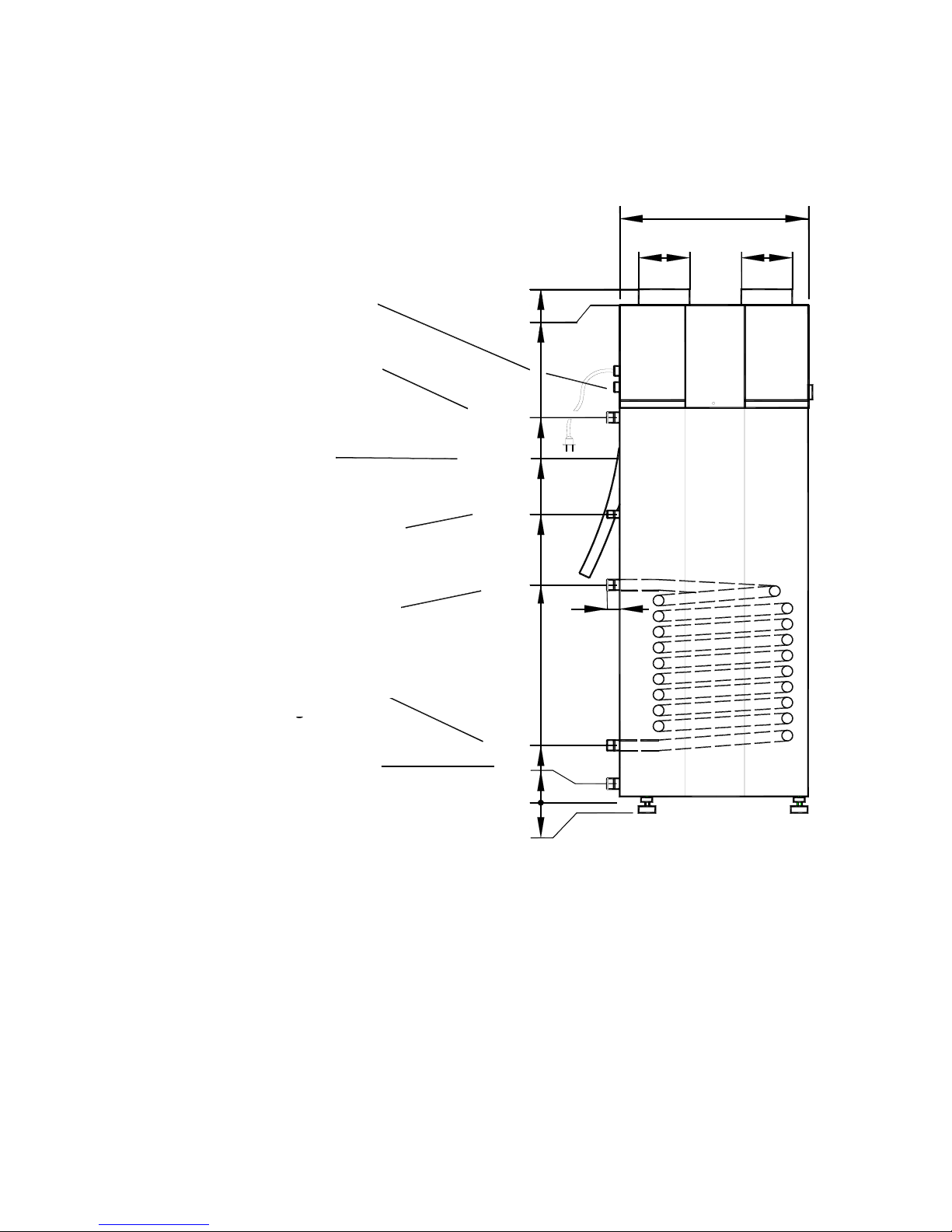
The water connections (Fig. 1) are located at the rear of the unit.
➨
Note !
-
Circulation line
From an energy-efficiency point of view, the provision of a circulation line should be dispensed with, if possible.
If a circulation line for the hot water distribution system is connected, it must be fitted with a valve or similar
device enabling it to be shut off to avoid any unnecessary loss of energy. Enabling the circulation is effected as
required (time or on-demand control).
-
Condensate drain
: note section "Connection of Condensate Line".
Fig. 1: Water connections
(
*
unique to HPWH with internal tubular heat exchanger )
(Leitungseinführungen
für Anschluß zweiter
Wärmeerzeuger)
Warmwasserauslauf
R1" Außengewinde
Kondesatschlauch-
ausführung
Zirkulationsleitung
R 3/4" Außengewinde
Heizwasservorlauf
R1" Außengewinde
Heizwasserrücklauf
R1" Außengewinde
Kaltwasserzulauf
R1" Außengewinde
20 - 35
0
220
55
ca. 50
720
918
Ø
160
Ø
160
1226
1620
1660
660
950
*
*
*
(Cable entries for
connection of suppl.
heat source)
Hot water outlet
external thread R1”
Condensate hose
leadthrough
Circulation line
external thread R3/4”
Hot water flow
external thread R1”
Hot water return
external thread R1”
Cold water inlet
external thread R1”
Page 6
6
2.3 Safety and Control Devices
The HPWH is equipped with the following safety features:
2.3.1 High-pressure pressostat (HP)
The high-pressure pressostat protects the heat pump from excessive operating pressures in the refrigeration
cycle. In the case of a malfunction, the pressostat switches off the heat pump. The heat pump is restarted
automatically as soon as the pressure in the refrigeration cycle has dropped to an acceptable level.
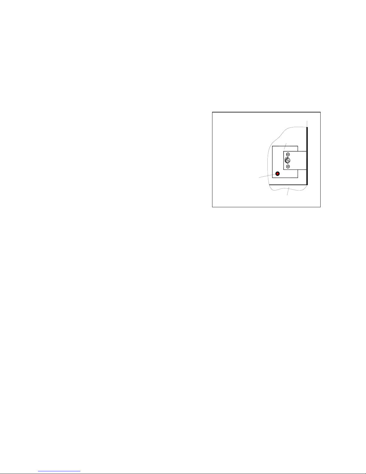
2.3.2 Safety temperature limiter for immersion heater (STL)
The STL protects the hot water installation from excessive
temperature increases.
When the preset switching value (99 °C) is exceeded, the
immersion heater is switched off.
The immersion heater cannot be restarted unless the hot
water temperature has fallen to ≤ 90 °C and the reset
button (Fig. 2) on the STL has subsequently been pressed
(may be performed by qualified personnel only!).
Fig 2: Resetting STL
2.3.3 Appliance fuse
For internal protection, the HPWH is provided with a separate fuse. This fine-wire fuse (1.25 A slow fuse) is
housed within a "screw plug device" (can be unscrewed in the middle) on the side where the internal electrical
connections (in the area adjacent to terminal strip X1) are located.
In addition, the HPWH is equipped with the following regulating and control devices:
2.3.4 Temperature controller for immersion heater (TR)
The temperature controller for the immersion heater regulates the water temperature in the immersion heater
mode of heating. The maximum temperature of this controller is factory-set at 65 °C (the controller is installed in a
common housing together with the STL). The temperature setting can be changed by means of a suitable tool
(see Fig. 2). Any change of this setting may only be performed by qualified persons!
In the automatic mode of operation (activation via air temperature sensor, see 2.3.6), the water is heated by the
immersion heater up to the preset fixed heat pump setpoint (approx. 58°C). When the immersion heater is
manually activated to operate in the continuous mode, the domestic water is heated until the preset maximum
temperature of the immersion heater controller is reached. (The immersion heater – with appropriate additional
wiring – may, as an option, also be designed for external activation – see section "Electrical connection“).
2.3.5 Electronic heat pump temperature controller
The temperature control inside the hot water storage tank and the control of the compressor operation is effected
by an electronic controller. It senses the water temperature with the aid of a sensor and keeps the preset fixed
setpoint at a nearly constant level.
2.3.6 Air temperature sensor
This electronic sensor senses the air inlet temperature of the HPWH (immediately at the evaporator inlet). If the
air temperature drops below 14°C water heating is automatically switched from the heat pump mode to the
immersion heater mode of operation.
85°
30°
B3
F2
STL
Partition
Panel
Reset button
Page 7
7
3. Storage and Transport
3.1 General Requirements
As a rule, the HPWH is to be stored or transported in its shipping box in upright position and
without water
charge
. For a transport over short distances, and provided due care is exercised, an inclination angle of up to 45°
is permitted. Both during transport and storage, ambient temperatures of -20 to +60 °C are permissible.
3.1.1 Transport using a forklift
(or lift truck)
When transported by a fork lift, the HPWH must remain mounted on the pallet. The lifting rate should be kept to a
minimum. Due to its top-heaviness, the HPWH must be secured against tipping over. To prevent any damage, the
HPWH must be placed on a level surface.
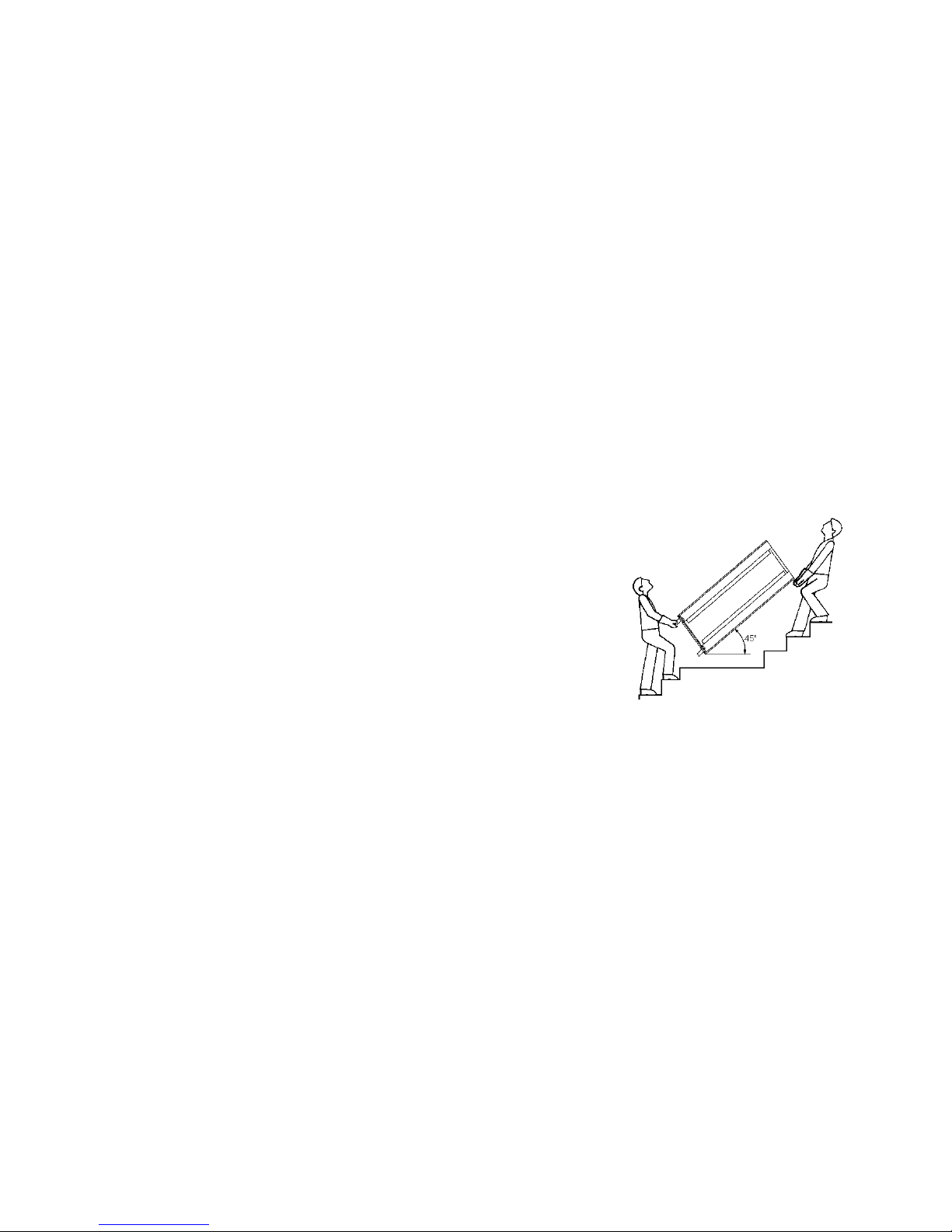
3.1.2 Manual transport
For the manual transport, the wooden pallet can be used for the bottom part. Using ropes or carrying straps
(which can be placed around the jacket of the storage tank and secured to the water tube nipples), a second or
third handling configuration is possible. With this type of handling (applies to the transport by hand truck as well),
care must be taken that the
max. permissible inclination angle of 45°
is not exceeded (see Figure). If transport
in an inclined position cannot be avoided, the HPWH ("heat pump" switch) should be taken into operation one
hour after it has been moved into final position at the earliest.
Caution! Do not lift the unit by its cover
(the cover is not designed to withstand heavy weights ! The
appliance cover must be relieved from the weight of the unit
during transport by taking appropriate measures or using auxiliary
aids)
4. Installation
4.1 Installation Site
CAUTION!
¾#
The HPWH must be sited in a
dry and freeze-proof room
, the room air temperature and/or the air taken in
by the HPCDW must be within a temperature range of 15 °C to 35 °C (required for heat pump operation).
¾#
In addition, the unit
must not
be installed in areas where there is an explosion hazard due to gases, vapours
or dust.
¾#
Adequate thermal insulation of areas adjacent to living spaces is recommended.
¾#
A condensate drain (with siphon) must be provided.
¾#
The air drawn in must be not excessively contaminated or heavily laden with dust.
¾#
The floor surface must have adequate load bearing capability (the estimated HPWH weight is 410 kg when
fully charged!).
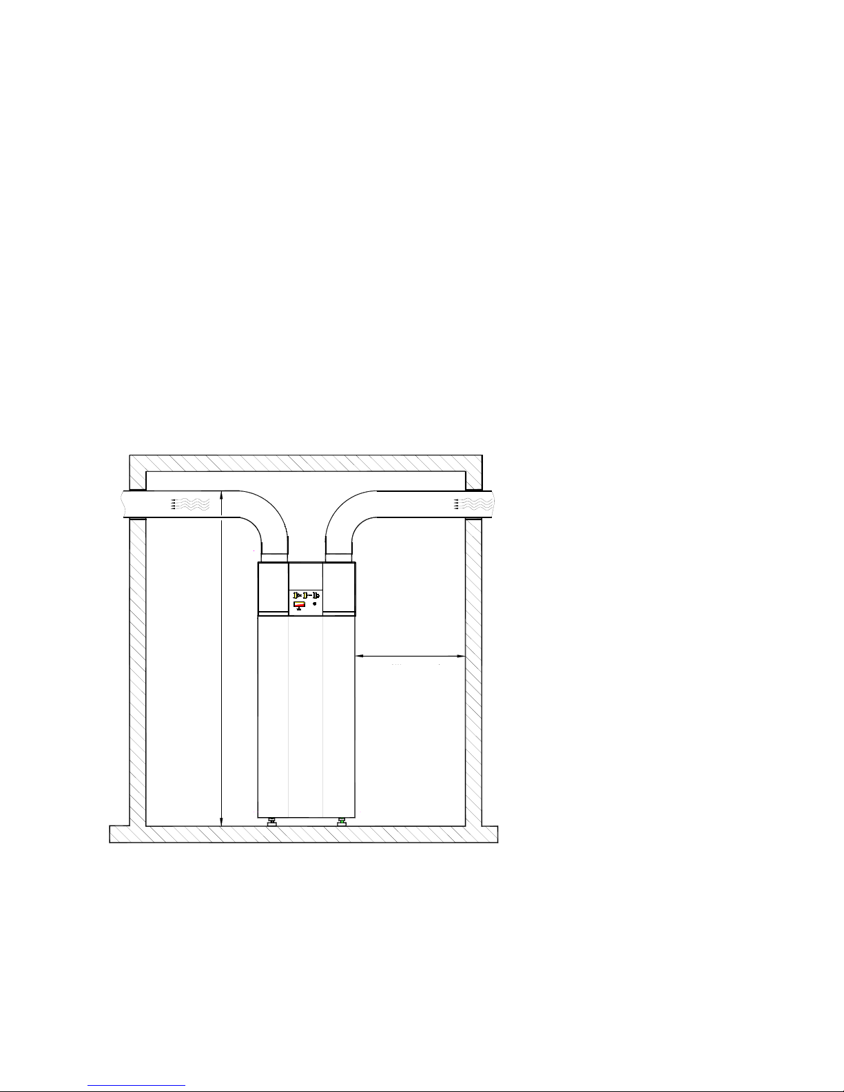
For the performance of maintenance and repair work clearances of at least 0.6 m must be maintained all around
the unit. If the HPWH is primarily operated as a hot water unit, rather than a ventilation unit, i.e.
without airducts
or airduct elbows
(➠"free-blowing“ installation), a minimum ceiling height of 2.5 m (see Fig. 4) is required (for
efficient operation). The connection to the HPWH is effected (optionally) by means of insulated airducts (NW 160)
which must not exceed a
total
length of 10 m.
Fig. 3: Transport of the unit
Page 8
8
The notices below apply to the connection of the HPWH to exhaust air duct systems:
Standardised exhaust air systems:
Standardised exhaust air distribution systems with decentralised outside air valves are offered for use with the
HPWH. The connection of these systems to the unit is accomplished via a flexible, sound and heat insulated
airduct (DN 160). This airduct is employed for both exhaust air and outlet air.
The mounting instructions of the individual exhaust air system must be observed.
Where it can be expected that the operating noise of the system is transmitted into the rooms from which the
odour- and moisture-laden air is to be removed (e.g. in the case of very short air duct runs) a suitable duct
silencer (DN 160) is to be mounted on the exhaust-air side of the compact residential ventilation unit in addition.
Customised exhaust air systems:
If the exhaust air system uses rigid ductwork (e.g. spiral-wound ducting, flat ducts), a flexible transition (e.g.
flexible tubing with a total length of approx. 1m) should be selected for vibration decoupling purposes between
duct network and the exhaust air and outlet air pipe connectors of the unit).
On the exhaust air side, a suitable duct silencer should be used in order to avoid any transmission of the
operating noise of the ventilation unit.
Important notices:
- Suitable exhaust air filters should always be provided in the airduct system to prevent any contamination of the
unit and the heat exchangers.
- The outside of the exhaust ducting network should always be provided with diffusion-resistant insulation to
protect it from heat losses and the formation of condensation water if they ducts are routed through rooms (e.g.
attic, basement, etc.) that are colder than the room from which the waste air was exhausted.
Fig. 4: Installation requirements
4.2 Installation
¾
From the underside of the pallet, remove the three M12 bolts securing the pallet to the unit as a shipping
safety measure.
¾
Remove the pallet and mount the three levelling feet (M12 bolts – contained in the polybag, secured to the
storage tank pipe nipple).
¾
Site the HPWH and adjust the unit so that it is
perpendicular
by adjusting the levelling feet! Then tighten the
check nuts provided on the levelling feet.
( 0.6 m maintenance and
service clearance spaces
all around the unit )
( Wartungs- und
Servicefreiraum
allseitig um das
Gerät )
ca. 2,0 m
0,6 m
AbluftFortluft
Outlet air
Exhaust air
approx. 2.0 m
Page 9

9
5. Mounting
5.1 Connection of Water Piping
The nominal pipe widths of the field-installed sanitary installations must be determined on the basis of the
available water pressure and the expected pressure drops within the piping system.
The water-side
installation
has to be executed in compliance with DIN 1988 (see appendix – in the case of
excessive water pipe pressure, a pressure relief valve is to be provided, among other things !)
The water pipes may be of the rigid or flexible type. The materials used in the piping system must be chemically
compatible in order to prevent any corrosion damage (see section Commissioning).
Caution!
When installing the pipework on the customer's site, any contamination of the piping
system must be avoided (pipes may have to be flushed prior to the connection of the
HPWH)!
5.2 Connection of condensate line
The condensate hose is passed through the foil-faced insulation jacket on the rear of the unit. The condensate
hose must be routed in such a way that any condensate which may form can drain without obstruction.
At the end of the condensate hose a
sealing lip valve
(that opens without pressure) is provided which
must also
be relocated
when the condensate hose is shortened (valve can be easily removed and reinstalled). In particular,
this valve is required if rather long air hoses are installed on the unit, or an upstream filter is installed on the
exhaust air side. The condensate has to be drained into a siphon (or, as an alternative, into a collecting vessel
which would have to be emptied regularly (see also Maintenance notice under 7.1).
5.3 Electrical Connection
The HPWH is pre-wired, ready for connection, the power is supplied via the mains cable connected to a wall outlet
with earthing contact (~230 V, 50 Hz). This outlet must be accessible also after the installation has been
completed.
For the connection of the remote control device, a separate cable ( 6-pole with a minimum wire cross-section of
0.75 mm
2
and max. outside diameter of 13 mm) must be inserted into the unit through the screwed cable gland
provided for this purpose, which also serves as a strain relief.
For the control of external devices for the supplementary heat source (applies only to HPWH with internal heat
exchanger), a separate cable must be fed into the unit as well. The terminal (X1 – 9/10/PE) with a potential-free
contact for the control (ON/OFF) of the external ancillary equipment (pump, solenoid valve, etc.) is located on the
partition inside the unit.
The external supply leads must be fed through the partition through the free cable bushing
provided for this purpose. It is necessary to remove the plastic hood of the HPWH to make these electrical
connections.
External immersion heater control
As an option, it is possible to configure the immersion heater in such a way that in addition to the activation by the
"immersion heater" switch on the operating panel on the HPWH it is also possible to activate the electric heating
element remotely (e.g. by using a timer). A potential-free contact on the external switchgear must be available for
this connection; in addition, another wire (min. 2 x 1.0 mm
2
/ max. outside dia. 10 mm) must be introduced into the
unit and clamped to terminals 7 and 8 of terminal strip X1.
9 + 10 Connection for the control of
external ancillar
y eq
uipment
1
1
/
3(
3(
1
1
/
3(
3(
43
<
;
:
9
8
7
6
43
<
;
:
9
8
7
6
X1
5
4
5
4
1 – 6 Connection of remote control
connecting lead
7 + 8 Connection for external
immersion heater activation
(
option
)
Fig. 5 : Terminals on partition wall
Page 10

10
6. Commissioning
6.1 Hot Water Circuit
➨➨➨➨
Caution!
The HPWH may only be operated with the unit filled with water!
6.1.1 Hot water circuit requirements
On the consumer side, the following materials may be incorporated into the water circuit:
Â
copper  stainless steel  brass  plastic
Depending on the materials used in the hot water circuit (installation to be provided by the customer), corrosion
damage may occur due to material incompatibilities. This must be taken into account, in particular where
galvanised materials and those containing aluminium are used. A filter may have to be provided if there is a
danger of water becoming contaminated during operation.
6.1.2 Commissioning of the hot water system
• All installations involving the water and air circuits as well as all electrical installations must have been
properly executed and completed.
•
Fill
hot water circuit via external connection
.
•
Bleed
the hot water circuit (open hot water taps at the topmost points of use until no more air escapes).
• Perform a
leak test
of the entire hot water circuit.
• Connect the unit to the
power supply
.
•
Turn on
the "heat pump“ switch (Fig. 6) and the slide switch on the remote control (Fig. 7).
• An appropriate heat-up time is required until the max. water temperature is attained (see Appendix, Technical
Data)
• Water heating by means of a
supplementary heat source
(applies only to HPWH with int. heat exchanger) is
possible by switching on the charging pump for the heat exchanger (Fig. 6) (provided the required external
electrical connection has been established).
6.2 Operation of the HPWH
6.2.1 Operating panel
Temperature display
The sensor of the thermostat (analog remote thermometer with trend display) senses the hot water temperature in
the upper section of the hot water tank. The display is located in the operating panel
.
Temperature display
35 °C 70 °C
blue
red
Page 11

11
6.2.2 Remote control
The wall-mounted remote control (Fig. 7) enables the HPWH to be switched on and off as well any one of the
three fan speed settings to be selected (see Table).
Slide switch Description
1
Hot water preparation by heat pump
* a
nd fan On /Off
2
Selection of fan speed (fan setting = 95 m³/h, II = 185 m³/h, III = 300 m³/h)
The remote control is surface-mounted. To facilitate
connection, it is recommended that the housing be installed
over a flush box (mounting instructions are supplied with the
remote control).
The connection between HPWH and remote control is to be
effected by customers using a 6-pole connecting lead (see
section "Electrical connection").
* Heat pump operation cannot be activated or deactivated
from the remote control unless the "heat pump" switch was
activated on the unit beforehand.
Note: Continuous operation of the electric heating element
cannot be controlled via remote control (see section 5.3 "External
immersion heater control")
In switch position I it is
possible to activate a
supplementary heat source
"Heat exchanger" switch
*
Switch position O Æheat pump is
OFF , in switch position
åååå/
the heat pump is in operation
"
"
In switch pos. I the immersion heater is
continuously switched on, in pos. the
immersion heater is in the automatic mode
"Immersion heater" switch
Temperature display see above
1
2
Fig. 7 : Remote control
Fig. 6: Operating panel
(
*
shown is the operating panel of
the HPWH with internal heat
exchanger; on HPWH without internal
heat exchanger the "heat exchanger"
switch is dispensed with )
Page 12

12
Ventilation mode
If the 'heat pump' switch on the heat pump is in position “ ❍❍❍❍ “ (Off), the HPWH can be operated in the ventilation
mode, provided the slide switch '1' is in position " I ". In this case, three ventilation settings can be selected
without the water heating function of the heat pump being activated.
Heat pump mode
If the 'heat pump' switch on the HPWH is activated (position “
“) and the slide switch on the remote control is in
position " I ", water heating, if required, is carried out by the heat pump. In this case, the fan will automatically be
set to a more effective (next higher) setting by the electronic controller.
6.2.3 'Heat pump' switch
If the 'heat pump' switch is placed in position “ “ (On), the heat pump is ready for operation and operating
(depending on the switch position on the remote control) until the max. heat pump temperature is reached.
6.2.4 'Immersion heater' switch
The integrated 1.5 kW heating element can be activated by means of the 'immersion heater' switch when there is
an increased demand for hot water or if a higher hot water temperature (> 58 ±2 °C) is desired.
When the 'immersion heater' switch is in position
" I "
, the tank content is heated up to the maximum temperature
of the immersion heater controller (factory setting 65 °C); at hot water temperatures > 58 °C, hot water preparation
is effected exclusively by the immersion heater. As an option, the immersion heater can also be configured for
external activation (see item 5.3). When the 'immersion heater' switch is in position “
” (automatic mode), the
tank content is heated (58°C) by the immersion heater at exhaust air temperatures of
<14 °C.
Note
➪➪➪➪
Immersion heater controller
The immersion heater controller is a second control device for the operating range of the electric immersion
heater that operates independently of the hot water controller. The factory-set switch-off temperature of 65 °C can
be changed by a qualified expert (see item 2.3)
6.2.5 'Heat exchanger' switch
(unique to LBW300W)
Actuating this switch enables external heat exchanger operation, i.e. water heating (e.g. in winter) can be
performed using a supplementary heat source (e.g. boiler, solar system, etc.), provided the required external
electrical connection has been established. The regulation of the hot water temperature takes place via the
electronic controller of the HPWH.
•••• Sensor tube for external temperature sensor
On the rear of the HPWH, a vertical sensor tube,
(inside ∅ 12mm) for an external temperature sensor
(the opening in the base plate is sealed with a
bushing socket) and in the rear panel a free cable
bushing are provided.
Fig. 9: Mounting position of external temperature sensor
(shown with appliance hood removed)
Page 13

13
7. Maintenance / Service
CAUTION!
Prior to opening the HPWH, the unit must be disconnected from the power supply; be careful of fan that
may still be rotating!
General
The heat pump water heater is nearly maintenance-free. A few days following the commissioning procedure, a
visual check for possible leaks in the water system or clogging of the condensate drain is to be performed once.
No maintenance activities need to be performed on the refrigeration cycle of the heat pump.
For cleaning the HPWH, simply use a damp cloth and some soapy water. Caution! Do not allow water to come in
contact with the operating controls. Prior to commencing the cleaning procedure, withdraw the mains plug or
disconnect the unit from the power supply.
7.1 Water Circuit / Condensate Drain
The inspection of the water circuit is limited to any filters that may have been field-installed, and the performance
of leak tests. The condensate hose must not be kinked (condensate must be able to drain freely). Dirty water
filters have to be cleaned and replaced, if necessary. The sealing lip valve provided at the condensate hose end
must be periodically checked and cleaned, if necessary.
7.2 Air Circuit
The maintenance activities on the unit are limited to the cleaning of the evaporator, whenever required.
Caution!
There is a hazard of injury from sharp-edged fins. Fins must not be distorted or damaged!
The air filters used in exhaust air systems must regularly be checked for contamination and be cleaned or
replaced, if necessary.
Page 14

14
7.3 Sacrificial Anode
The sacrificial anode installed in the hot water tank for corrosion protection purposes, must be checked electrically
on a regular basis, at least every two years
after commissioning, and be replaced, if necessary. The electrical
check is to be conducted by means of a suitable ammeter
without
draining the water in the tank.
Procedure:
n Withdraw PE conductor from tab of sacrificial anode.
o Connect ammeter (0...50 mA) between PE conductor and tab.
p Evaluation of wear of sacrificial anode:
Measured value > 1 mA ➪ sacrificial anode is okay.
Measured value < 1 mA ➪ sacrificial anode must be checked or replaced.
If an unambiguous electrical check is not possible, we recommend that a visual inspection of the sacrificial anode
be performed by a qualified expert.
(For a replacement of the sacrificial anode that may be necessary [to be performed by an expert], the water must
be drained from the tank via the drain valve (to be provided upon installation – see appendix.
Caution
: Sacrificial anodes that are impaired in their function will reduce the life of the unit!
Fig. 10: Sacrificial anode
(sectional view of tank)
The sacrificial anode is screwed into the storage tank below
the immersion heater
(covered with a plastic cap)
Page 15

15
8. Malfunctions / Troubleshooting
( for the user )
Heat pump fails to run
!
Please check whether
ÖÖÖÖ
the plug is plugged in
ÖÖÖÖ
the power switch is switched on
Ö
ÖÖ
Ö
the switches on the remote control are switched on
ÖÖÖÖ
voltage is present at the wall outlet
ÖÖÖÖ
the air intake temperature is ≥ 14°C
ÖÖÖÖ
the hot water temperature has already reached 58°C (or more)
(Notice for the expert:
Ö
ÖÖ
Ö
has the internal appliance fuse tripped ? )
Heat pump switches off prematurely
(setpoint temperature has not been reached yet)
Please check whether
ÖÖÖÖ
airducts are kinked or their openings are closed, or
air filters that may be provided are severely contaminated (clogged)
Condensate fails to drain
(
water at or under the unit
)
Please check whether
Ö
ÖÖ
Ö
the sealing lip valve at the end of the condensate hose is contaminated or
clogged; clean it, necessary. The valve can be easily removed and reinstalled.
ÖÖÖÖ####
the air supply / air discharge rate is greatly reduced (kinked airduct / clogged
air filter)
If the malfunction cannot be corrected based on the above questions, please consult your installer or
customer service
.
9.
Decommissioning
Activities to be performed
:
•
Disconnect
HPWH f
rom the power source
.
•
Completely shut off water circuit
(hot water, cold water and circulation line) and drain the hot water storage
tank.
10.
Environmental Requirements
Environment-relevant requirements regarding the recovery, reuse and disposal of service fuels and components
in accordance with DIN EN 378 must be adhered to when repairing or decommissioning the
HPWH.
Caution!
Work on the hot water heat pump may only be performed by competent persons! Accident prevention
regulations must be adhered to!
Page 16

16
11.1
Refrigeration Cycle with Legend
1 Compressor 8 Control electronics 15 Evaporator
2 Pressostat HP 9 Safety temperature limiter 16 Fan
3 Condenser 10 Temp. controller immers. heater 17 Check valve
4 Hot water tank 11 Temperature display 18 Insulation
5 Heat exchanger
(not all types)
12 Filter drier
6 Immersion heater 13 Expansion valve
7 Sacrificial anode 14 Air temperature thermostat
TC
13
18
16
15
14
1
18
12
2
3
7
4
6
11
10
9
8
PA-CO-H
TI-CO-L
TI-CO-H
TI
-CO-H
-C I -L
TI
TI
-CO-H
-C I -L
freie Tauchhülse
17
5
5
Page 17

17
11.2
Hydraulic Plumbing Diagram
1 Shut-off valve 6 Drain valve
2 Pressure-reducing valve 7 Diaphragm safety valve
3 Test valve
(to be mounted above tank edge)
4 Non-return valve 8 Circulating pump
5 Manometer connection 9 Drain
* on HPWH without internal heat exchanger, the connections for the suppl. heat source are dispensed
with, i.e. no heating water flow and return lines)
1
1
8
4
1
7
Warmwasser
Heizwasservorlauf
Zirkulation
(wenn erforderlich)
Heizwasserrücklauf
Kaltwasseranschluß nach DIN 1988
9
6
1
5
4
3
2
*
*
Hot water
Hot water flow
Circulation
(if required)
Hot water return
Cold water connection acc. to DIN 1988
Page 18

18
11.3 Connection Diagram of Heat Exchanger to Thermal Solar System
to heat
exchanger
Flow
to heat
exchanger
Return
Venting
Check valve
Stop-cock
Thermometer
from collector
Safety
valve
Pressure
gauge
Flowmeter
Stop-
cocks
Circulating
pump
to collector
Charging pump
Expansion vessel
Check valve
Stop-cock
Catchpan
Page 19

19
11.4 Circuit Diagram
LBW300 / LBW300LW
J1
14
14
11
K1
Ventila to r
M2
A1
K1
A2
S1
1
2
M1
+48V DC
KL1
day
L
night
PE
N
party
M
M
P
1
A
C
F3
C1
X1-1
L/N/PE ~ 230VAC - 50Hz
X1-2
21bar
F2
P >
2
1
Wärmepump e
21
22
E1
11
T >
B1/
F4
STB
TR
+65°C
+99°C
(+30 - +85°C )
12
S3
1
2
2
1
S2
Elektro - Heizstab
11
6543
X6
S5
S4
X6-1
X6-2
III
II
I
Fernbedienung
Fernbedienung
minus
KL2
N1
J1-4
J1-5
N1
J1-L
J1-N
N1
N1
J1-13
J1-14
N1
J1-11
J1-12
F1
Legende
B1 Regelthermostat-el. Heizung
C1 Anlaufkondensator Verdichter
E1 E lek tro-Heizs ta b
F1 Steuersicherung
F2 Pressostat Hochdruck
F3 Thermokontakt Verdichter
F4 Sicherheitsbegrenzer-Thermostat el.Heizstab
K1 R e la is Ve rd ic h te r
K2 R e la is a u f N1
K3 R e la is a u f N1
K4 R e la is a u f N1
M1 Ve rd ic h te r
M2 Ve n tilator m it Netzte il
N1 R egelplatin e
R1 NTC-Fühler Speichertemperatur
R2 N T C-Füh le r Ab luftte m pera tu r
R3 Potentiometer Sollwert-Warmwasser
S1 Schalter Wärmepumpe
S2 Schalter el.Heizung
S3 Schalter externe Pumpe
S4 Schalter Wärmepumpe EIN/AUS über Fernbedienung
S5 Schalter Drehzahlumschaltung-Venti über Fernbedienung
X1 Klemmenleiste: Netzanschluss; externe Komponenten
J1-10 J1-2
J1-6 J1-7
-9
X1
3
4
5 6
L PEN
X1
Heizung "EIN-AUS" extern
Ansteuerung für externe Pumpe
1,25A Tr
250V
X1
7
8
X1
9
10
L N 6 7 2 9 103 4 5
11 12 13 14
X4
Platine N1
Sollwert
Speichertemp.
Ablufttemp.
R1 R2R3
Ansteuerung für externe Pumpe ect.
Heizu n g "EIN/AUS" von e x te rn
B1 Regulating thermostat, electr. Heating
C1 Starting capacitor, compressor
C2 Operating capacitor, fan
E1 El. immersion heater
F1 Control-circuit fuse
F2 HP pressostat
F3 Thermal contact, compressor
F4 Safety limiter thermostat, el. heating element
K1 Relay, compressor
K2 Relay on N1
K3 Relay on N1
K4 Relay on N1 N1 Controller board R1 NTC sensor, storage tank temperature
R2 NTC sensor, exhaust air temperature
R3 Potentiometer, hot water setpoint
S1 Switch, heat pump
S2 Switch, el. heating
S3 Switch, external pump
S4 Switch, heat pump ON/OFF via remote control
S5 Switch, fan speed switchover via remote control
X1 Terminal strip: mains connection; external
components
Exhaust air temp.
Storage tank temp.
Setpoint
Heating “ON/OFF”, external
Control of external pump
Board N1
Control of external pump Heating “ON/OFF”, external
Electric heating element Heat pump Fan
Remote control
Remote control
Page 20

20
11.5 Technical Data
Heat Pump Water Heater LBW 300 LBW 300LW
Type
without additional
tubular heat exchanger
with additional tubular
heat exchanger
Nominal tank capacity (L) 300 290
Tank material (enamelled acc. to DIN 4753) enamelled steel enamelled steel
Nominal tank pressure (bar) 10 10
Dimensions height
(max)
x diameter (cm) 169.5 x 70 169.5 x 70
Weight (without charge) (kg) 110 approx. 125
Electrical connection ( plug-in device – cable length approx.
2.7
m)
230 V ~ 50 Hz 230 V ~ 50 Hz
Fusing (A) 16 16
Refrigerant R 134a, charge weight (kg) 1.0 1.0
Performance data
Temperature, operating range (exhaust air)
(°C)
15 to 30 15 to 30
Water temperature in heat pump mode – fixed setpoint (°C) 58 58
Heat-up time from 15°C to 55°C
(at L20 / F50)
1)
(h) 9.5 9.4
Power consumption, electr. back-up heater (W) 1 500 1 500
Average power consumption
at 45 °C (W) 410 410
Average heat output 2) at 55 °C (W) approx. 1400 approx. 1400
COP (t) acc. to TNO 4.05 4.05
COP (t) acc. to EN 255 Part 3 4.4 4.4
Sound pressure level at 300 m³/h
3)
(dB(A)) 44 44
Air flow rate for ventilation mode (
3-speed operation)
(m³/h) 95 , 185 , 300 95 , 185 , 300
Air flow rate, heat pump mode (m³/h) 185 , 300 185 , 300
External pressure at 300 m³/h (pa) 250 250
Airduct connection, diameter, exhaust air/outlet air (mm)
160 160
Maximum airduct connection length (m) 10 10
Sensor tube Ø
inside
(
for sensor – heat exchanger mode
) (mm) - - - 12
Connection, circulation line external thread R3/4" R3/4"
Connection, hot water outlet external thread R1“ R1“
Connection, cold water supply external thread R1“ R1“
Internal heat exchanger – transfer surface (m²) - - - 1.45
1)
At fan setting III (300 m³/h)
2) Heat-up process of nominal content from 15 °C to 45 °C at L20 / F50 = 20°C exhaust air temperature, 50%
exhaust air humidity and fan setting III
3) At a distance of 1m
(in the case of self-contained units or installations without exhaust air duct or 90°-elbow on exhaus
t
air side
Page 21

The undersigned
hereby confirms that the design and construction of the product(s) referenced below,
in the version placed on the market by us, conform to the relevant fundamental provisions of
the applicable EC directives.
This declaration becomes invalidated if any modifications are made to the product(s) without
our prior authorisation.
KKW Kulmbacher Klimageräte-Werk GmbH,
Am Goldenen Feld 18
D - 95326 Kulmbach / Allemagne
EC Manufacturer‘s Declaration
Designation of the product(s):
Hot water heat pumps
containing R134A
Type(s):
Order No.:
LBW 300
LBW 300LW
346 330
346 340
Kulmbach, 29.04.2004
EC Directives
Harmonized EN Standards:
EC Low Voltage Directive
(73/23/EEC)
EC EMC Directive
(89/336/EEC)
Pressure Equipment Directive
(97/23/EEC)
EN 255 1997
EN 378 1994
EN 60335-1/A11/A12 1995/1996
A13/A14 1998/1998
EN 60335-2-40 1998
EN 55014-1/A1 1993/1997
EN 55014-2 1997
National Standards/Directives
DACH
VBG20 NEN 5128 SVTI
©
Wolfgang Weinhold
General Manager
Mathias Huprich
Technical Director
Page 22

22
Page 23

23
Page 24

24
Subject to technical changes
 Loading...