

Page 1

ContactDetails
Pleasenotethatsomeofthecontactdetailson
thisPDFdocumentmaynotbecurrent.
Pleaseusethefollowingdetailsifyouneedto
contactus:
Telephone:08448793588
Email:customer.services@gdcgroup.co.uk
Thecustomersupportsectionofourwebsitealsofeaturesawide
rangeofinformationwhichmaybeofusetoyouandisavailable
24hoursaday.Itincludes:
• Operatingandinstallationinstructions
• Easy‘Howtouse’guidesforstorageheaters
• Serviceandrepairs
• Where
tobuyourproducts
• Literaturedownloads
• Heatingrequirementcalculator
Visit‐www.dimplex.co.uk/support
A division of GDC Group Ltd
Millbr ook House Grange Drive Hedge End Sout hampton SO30 2DF
ww w.d implex.co.uk
Registered No: 1313016 England
VAT GB 287 1315 50004
EEE Producer Registration Numb er –
WEE/ GE0057TS
Paper f rom sustainabl e sources
Page 2
LA 6 MI
LA 9 MI
LA 12 MI
LA 16 MI
Inverter air to water heat pump for
outdoor installation
Technical planning manual
08/60393/0
Page 3
Page 2
Supporting documents
The following documents are available to aid in the planning, installation, operation and maintenance of the Air-eau heat
pumps:
Technical manuals
Contains the necessary information required during the planning stages.
Air-eau inverter heat pumps packages (this document)
SmartRad
Installation instructions
Contains the necessary information required during the installation.
Air-eau inverter air-to water heat pump system packages
LA MI settings function & programming overview
EC-eau cylinders
SmartRad
User guides
Contains the necessary information for the user for operation and maintenance of the system
Air-eau heat pumps (Pack 1 and 2 – standard heating and DHW) for standard users
Air-eau heat pumps (Pack 1 and 2 – standard heating and DHW) for sheltered housing
Horstmann wall mounted room thermostat
The installation of an Air-eau heat pump should only be carried out by a suitably trained and
competent person who is approved by Dimplex. All installations should be in accordance
with this planning manual to ensure efficient operation.
Page 4

Page 3
Contents
Supporting documents ......................................................................................................................................................... 2
Section 1: Introduction ............................................................................................................................................................. 6
What are the benefits of a heat pump? ................................................................................................................................ 6
How a heat pump works ....................................................................................................................................................... 6
Intended Use ........................................................................................................................................................................ 6
Air as a heat source ............................................................................................................................................................. 6
Advantages of inverter compressors .................................................................................................................................... 6
Advantages of fixed speed compressors .............................................................................................................................. 7
Heat pump labelling .............................................................................................................................................................. 7
Comparison of the LA MS and LA MI ranges ....................................................................................................................... 7
Section 2: Selection and sizing of the heat pump ..................................................................................................................... 8
Process to select a heat pump ............................................................................................................................................. 8
Mono energy operation......................................................................................................................................................... 8
Accurately determining the building‟s heat loss .................................................................................................................... 8
Estimating the building‟s heat loss ....................................................................................................................................... 9
Dimplex design service......................................................................................................................................................... 9
Drying-out of buildings .......................................................................................................................................................... 9
Sizing example 1 ................................................................................................................................................................ 10
Sizing example 2 ................................................................................................................................................................ 10
Section 3: System controls in a domestic setting .................................................................................................................... 11
Boiler inter lock ................................................................................................................................................................... 11
Horstmann PRT thermostat ................................................................................................................................................ 11
Heat Pump Controller ......................................................................................................................................................... 11
Weather compensation....................................................................................................................................................... 11
Section 4: Selection of heat emitters and flow temperatures .................................................................................................. 12
Minimising the flow temperature ......................................................................................................................................... 12
Considerations for fan convectors ...................................................................................................................................... 12
Section 5: DHW preparation with inverter heat pumps ........................................................................................................... 13
Dimplex EC-Eau cylinder range ......................................................................................................................................... 13
Dimplex ECS Combination DHW and Buffer Cylinders ...................................................................................................... 13
Heat pump power for hot water preparation ....................................................................................................................... 13
Selecting a DHW cylinder ................................................................................................................................................... 13
Cylinder volume and reheat ................................................................................................................................................ 14
Cylinder replacement ......................................................................................................................................................... 14
Selecting and controlling the DHW temperature ................................................................................................................. 14
Sterilisation ......................................................................................................................................................................... 15
Secondary circulation pipes ................................................................................................................................................ 15
Section 6: Installation considerations ...................................................................................................................................... 16
Physical location ................................................................................................................................................................. 16
Fixing of the heat pump ...................................................................................................................................................... 16
Wall mounting ..................................................................................................................................................................... 16
Ventilation ........................................................................................................................................................................... 17
Page 5

Page 4
Minimum maintenance clearances ..................................................................................................................................... 17
Sound insulation measures ................................................................................................................................................ 17
Air quality ............................................................................................................................................................................ 18
Local planning regulation.................................................................................................................................................... 18
MCS Planning Standard ..................................................................................................................................................... 18
Town and Country planning, England ................................................................................................................................ 18
Planning in Wales and Northern Ireland ............................................................................................................................. 19
Town and Country planning, Scotland ................................................................................................................................ 20
Section 7: Heating System Connection .................................................................................................................................. 21
External pipe work .............................................................................................................................................................. 21
Minimum water volume....................................................................................................................................................... 21
Buffer tank .......................................................................................................................................................................... 21
Minimum heating water flow rate ........................................................................................................................................ 21
Taconova flow checker ....................................................................................................................................................... 21
Plumbing connections ........................................................................................................................................................ 22
Frost protection .................................................................................................................................................................. 22
Condensate ........................................................................................................................................................................ 22
Flushing the system ........................................................................................................................................................... 22
Filter ................................................................................................................................................................................... 23
Filling the system ................................................................................................................................................................ 23
De-aeration ......................................................................................................................................................................... 23
Adjusting the water flow rate .............................................................................................................................................. 23
Expansion vessel sizing ..................................................................................................................................................... 23
2 port valves ....................................................................................................................................................................... 24
Controlling DHW temperature ............................................................................................................................................ 24
Section 8: Electrical Connection ............................................................................................................................................. 25
Routing of cables within the heat pump .............................................................................................................................. 25
Ducting cables .................................................................................................................................................................... 25
Connection of the power supply to the Heat pump ............................................................................................................. 26
Main power supply cable .................................................................................................................................................... 26
Inline flow boiler .................................................................................................................................................................. 28
Domestic hot water immersion ........................................................................................................................................... 28
Controller cable .................................................................................................................................................................. 29
Connection with the system ................................................................................................................................................ 30
Installation of the controller ................................................................................................................................................. 30
Section 9: System Health checks ........................................................................................................................................... 31
Heat pump .......................................................................................................................................................................... 31
Electrical ............................................................................................................................................................................. 31
Hydraulic ............................................................................................................................................................................ 31
Cylinder .............................................................................................................................................................................. 31
Wall mounted thermostat.................................................................................................................................................... 31
Heat pump controller .......................................................................................................................................................... 31
Section 10: Standard packages .............................................................................................................................................. 31
Package 1 and 2 ................................................................................................................................................................ 31
Page 6

Page 5
Package 1 and 2 – Plumbing Schematic ............................................................................................................................ 34
Package 1 and 2 – Micro wiring schematic (option 1 – immersion controlled direct) .......................................................... 35
Section 11: Technical specification of the LA MI range .......................................................................................................... 36
Approvals ........................................................................................................................................................................... 37
Performance Data .............................................................................................................................................................. 37
Performance Data .............................................................................................................................................................. 38
CE declaration of conformity .............................................................................................................................................. 39
LA 6 MI performance .......................................................................................................................................................... 40
LA 9 MI performance .......................................................................................................................................................... 42
LA 9 MI performance (continued) ....................................................................................................................................... 43
LA 12 MI performance ........................................................................................................................................................ 44
LA 16 MI performance ........................................................................................................................................................ 46
Product Dimensions LA 6 MI and LA 9 MI .......................................................................................................................... 48
Product Dimensions LA 12 MI and LA 16 MI ...................................................................................................................... 49
LA 6 MI and LA 9 MI Spare parts ....................................................................................................................................... 50
LA 12 MI and LA 16 MI Spare parts ................................................................................................................................... 55
Information for DHW cylinder with buffer - ECS125HP-580 .................................................................................................... 60
Information for DHW cylinder with buffer - ECS150HP/75-580 ............................................................................................... 61
Information for DHW cylinder with buffer - ECS210HP/75-580 ............................................................................................... 62
Page 7

Page 6
Section 1: Introduction
What are the benefits of a heat pump?
Large quantities of pollutants, such as carbon dioxide,
sulphur dioxide and nitrogen oxide are released from gas
or oil boilers used to heat our homes. A large percentage
of our energy supply comes from fossil fuels which have a
serious effect on our environment. Fuel security is also an
issue as our oil and gas reserves are limited and often
from volatile counties around the world. The way electrical
energy is generated will change in the future to favour
more renewable generation methods. A heat pump uses
electrical power that could come from a variety of sources
and it uses very efficiently.
How a heat pump works
A heat pump converts low grade heat from the
environment to high grade heat for space and DHW
heating using a refrigeration cycle. Surrounding air is
drawn in by the fan and passed over the evaporator. The
evaporator cools the air, i.e. it extracts heat from it. This
extracted heat is then raised in temperature via the
refrigeration cycle and then transferred to the condenser.
The heat is “pumped” to a higher temperature level by
increasing its pressure with the aid of an electrically driven
compressor.
Because the energy extracted from the air is transferred to
the heating water, this type of device is called an air-towater heat pump. The air-to-water heat pump consists of
the main components evaporator, fan and expansion
valve, as well as the low noise compressor, condenser
and electrical control system.
At low ambient temperatures, humidity accumulates on the
evaporator in the form of frost reducing the transfer of
heat. The evaporator is defrosted automatically by the
heat pump as required.
The refrigerant circuit is hermetically sealed. It contains
the Kyoto protocol approved refrigerant R410 with a GWP
value of 1725. It is CFC-free, does not deplete ozone and
is non-flammable.
Intended Use
This device is only intended for use as specified by
Dimplex as detailed within this technical manual. The airto-water heat pump is to be used exclusively for the
heating of heating water in a closed circuit. Any other use
beyond that intended by the manufacturer is prohibited.
Persons, especially children, who are not capable of
operating the device safely due to their physical, sensory
or mental abilities or due to their inexperience or lack of
knowledge, must not operate this device without
supervision or instruction by the person in charge.
Air as a heat source
The decision whether to install either an air source heat
pump or a ground source heat pump depends on the
following factors:
Investment costs:
In addition to the costs for the heat pump and the
heat emitter system (radiators and circulation pump),
the investment costs are heavily influenced by the
costs of tapping the heat source. Air is the easiest
heat source to tap as the heat pump is relatively
easy to position outside. Tapping the ground as a
heat source is more difficult. If the land area is
available horizontal loops are the most cost effective
way to install the ground collector. If boreholes are
used, due to the cost of mobilising the plant,
experience has shown that installations with less
than 10 boreholes are not economical.
Operating costs:
The seasonal performance factors of the heat pump
influences the operating cost. These are primarily
affected by the type of heat pump, the average heat
source temperature and the required heating flow
temperatures. Ground source heat pumps have
higher SPF‟s compared to air source heat pumps.
Advantages of inverter compressors
An inverter heat pump is able to modulate its‟ heat output
over a set range. The inverter compressor modulates its
output to keep the return temperature constant. If demand
increases the output of the compressor can increase to
keep the flow temperature constant. If the demand
decreases beyond the minimum setting of the compressor
it will turn off until the heating circuit temperature reduces.
A fix speed compressor will run at a constant speed until
the set temperature is reached. When the set point is
reached the compressor will turn off until the temperature
in the heating circuit drops to a hysteresis value. When
this value is reached the compressor will restart. The
compressor will cycle on and off to maintain the correct
temperature. If demand increases the fixed speed
compressor will be on more often.
Even though an inverter compressor cycles less, to ensure
optimum life expectancy an inverter compressor should
always be installed with a buffer tank to increase run times
and store energy for the defrost.
Correct selection of the heat pump, heat
emitters and circulation system is essential for
efficient operation of the entire system.
Page 8
Page 7
An inverter compressor starts gently ramping up to its
maximum speed over a couple of minutes meaning the
current increase is very gradual. The fixed speed
compressor has a larger starting current because it
doesn‟t turn on gradually. The starting current is smoothed
by an inbuilt soft-starter to keep it within acceptable limits.
The starting current does not cause any problems
because an in-built randomised time delay that ensures
multiple heat pumps to not turn on at the same time.
An inverter heat pump is able to modulate down its output
as the external temperature increases. A fixed speed heat
pump will run at a constant speed meaning that its output
increases with rising temperature. This means that an
inverter compressor could achieve slightly higher cylinder
temperatures for the same size coil although in practice
both types of compressor can achieve suitable cylinder
temperatures.
Advantages of fixed speed compressors
A fixed speed compressor is designed to work at the
optimum performance level all of the time. An inverter
compressor does not always work in the optimum zone
because it modulates its output to match the heat demand.
The „over-driving‟ of an inverter compressor causes it
efficiency to drop.
Since the output of both the fixed and inverter
compressors drop with decreasing temperature, there
becomes a point when a secondary heat source is
required to match the properties heat demand, known as
the Bivalent point. At lower temperatures an inverter
compressor and a fixed speed compressor are equally as
efficient despite the inverter needing more immersion
support.
Heat pump labelling
The product code for the inverter range of heat pumps
continues the same convention as the rest of Dimplex‟s
heat pump range.
Letter
Meaning
L
Luft (German for air)
A
Aus (German for outside)
##
Nominal kW rating
M
Mono (German for single phase)
I
Inverter
Table 1: Product coding convention
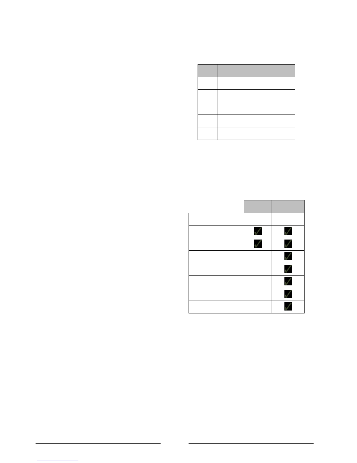
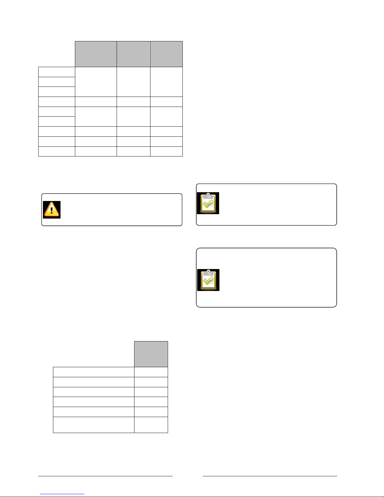
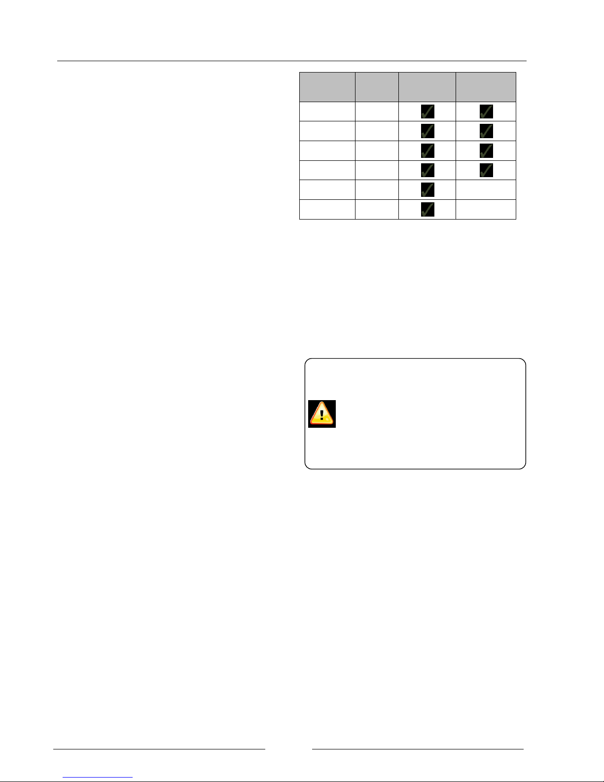
Comparison of the LA MS and LA MI ranges
The LA MI and LA MS range of heat pumps are ideal for
providing DHW and space heating. In addition, the MS
range of heat pumps also has a sophisticated controller
capable of controlling more complicated systems.
MI range
MS range
Compressor speed
Variable
Fixed
Heating only
Heating & DHW
Mixed heating circuits
Swimming pool
Solar Thermal
Boiler integration
Multiple heat pump
Table 2: Comparison of WPM and MI Range
Page 9
Page 8
Section 2: Selection and sizing of the heat pump
Process to select a heat pump
1. Confirm the building is suitable for a heat pump
installation as out lined in Section 6: Installation
considerations.
2. Accurately determine the buildings heat loss to EN
15316.
3. Decide on the maximum flow temperature.
4. Select the model of heat pump using the output
curves to EN14511
Mono energy operation
As the weather gets colder, the heat demand of the
building increases and the output of the heat pump
decreases. There becomes a tipping point where it is so
cold outside the output of the heat pump is not able to
heat the building alone. The LA MI range of heat pumps
are monoenergy heating devices. i.e. in the event of very
low external temperatures an electrically operated inline
flow boiler will automatically be activated to provide
additional heat and keep the building warm.
The heat pump should fully meet the heat consumption
down to a certain external temperature as specified by the
NHBC and summarised in Table 3. The MIS 3005 also
standard states outside design temperatures for different
locations in the UK. To comply with both pieces of advice
the system should be designed to operate to the lower of
the two design temperatures. If this is not the case, the
electrical inline flow boiler will operate more frequently and
increase the running costs.
External
temperature
England and Wales
-3C
Scotland
-5C
Table 3: External design temperatures (bivalent point) stated
by NHBC
Bivalent operation is when an additional heat source other
that electricity is used to supplement the heat load.
Integration of another boiler such as gas, oil or LPG is not
possible with the LA MI but is possible with Dimplex‟s
WPM range.
Accurately determining the building’s heat loss
It is essential to accurately calculate the buildings heat
loss to ensure the heat pump is correctly sized. The heat
loss of a building is calculated using details of the
buildings construction, individual room sizes, room
temperatures and air change rates.
Dimplex recommend calculating the buildings heat loss to
the standards defined in EN15316, this is also stipulated in
MIS 3005 which is required if the installation is going to be
MCS approved.
The total heat loss is made of two components; the fabric
losses and the ventilation heat losses. Fabric heat losses
are due to the transmission of heat by conduction though
the buildings structure such as windows, walls, roof and
floor. Ventilation heat losses are due to warm air escaping
the building and being replaced by cold air.
Total heat loss = Fabric losses + Ventilation losses
Fabric heat loss (W) = U x A x T
Where: U = U value (w/m2 C)
A = Area of the wall, window, ceiling or floor (m2)
T = Temperature difference on either side of the
insulation (C)
Typical U values
New build
Walls
0.35
Windows
2.00
Roof
0.18
Floor
0.25
Table 4: Example U values for Fabric heat loss calculation.
Further details can be found in Dom 8 - Design of total
heating systems.
Ventilation heat loss (W) = V x R x T x F
Where: V = Room volume (m3)
R = Air change rate per hour
T = Temperature difference of air in and out (C)
F = Ventilation Factor (W / m3 C)
It is beyond the scope of this document to give
all the necessary values to calculate the
buildings total heat loss. This section intends
to outline the process to remind the system
designer to find the necessary information.
Page 10
Page 9
Typical room
temperatures
Air
changes
per hour
Ventilation
factor
Living room
21
1
0.33
Dining room
Study
Kitchen
18
2
0.67
Bathroom
22
2
0.67
W.C
Bedroom
18
½
0.17
Hall
18
1 ½
0.50
Landing
18
1 ½
0.50
Table 5: Example of values used in the ventilation heat loss
calculation. For full details see BS 5449:1990
Estimating the building’s heat loss
The existing boiler cannot be used as a guide to determine
the actual heat consumption because boilers are often
over sized.
However, an approximate estimate can be made on the
basis of the existing energy consumption of the living
space to be heated and the specific heat consumption.
For early budgeting purposes a buildings heat loss can be
estimated based upon the floor area.
Estimated heat loss(W) = A x E
Where: A = Floor area (m2)
E = Estimated heat loss (W/m2)
Estimated
heat loss
per m2
High insulation new build
30 W/m2
New build (2002 regulations)
50 W/m2
1970‟s
80 W/m2
1930‟s
100 W/m2
Older than 1930‟s
120 W/m2
Older than 1930‟s with high
ceilings
150 W/m2
Table 6: Typical building heat loss per m2 used to estimate a
buildings heat loss
Dimplex design service
Dimplex offer a free of charge service to calculate a
buildings heat loss along with a full product and accessory
specification. Providing we receive the information below,
turnaround is usually 7-10 working days.
To request this service a form can be downloaded from
our website that should be sent in with the following
information:
Plan and elevation drawings [scale 1:50 or 1:100]
Construction U values
Type of scheme ie: domestic, commercial or
industrial
Internal and external design temperatures
required
Details of any special requirements or unusual
aspects to the building
Alternatively the form and CAD drawings can be
emailed to
Drying-out of buildings
When a house is being built, large quantities of water are
normally used for mortar, rendering, plaster and wall
paper, which only evaporates very slowly from the
building. In addition, rain can decisively increase the
humidity in the building's structure. This increased
humidity in the entire structure causes an increase in the
heat consumption of the house during the first two heating
periods. For this reason, buildings should be dried out
using specially designed dehumidifiers.
The heat pump is not designed for the
increased heat consumption required when a
building is being dried out. Some additional
heat is available in the form of an inline flow
preinstalled in the product. If a building is to
be dried out in autumn or winter, we
recommend installing an additional
temporary heating.
For further information about our design
service please visit:
http://www.dimplex.co.uk/products/renewable
_solutions/heating_design_service
Rules of thumb and estimates are suitable for
budget purposes but are not accurate enough
to calculate the building‟s heat loss in order to
select a heat pump.
Page 11
Page 10
Sizing example 1
Design
temperature
The property is in Manchester,
England – NHBC recommend 3C and CIBSE recommend -
2.2C. The design temperature is
therefore -3C.
Building
heat loss
The properties heat loss is
calculated to be 4.5kW at the
design temperature.
Flow
temperature
Has been selected at 55C as
radiators are going to be
installed.
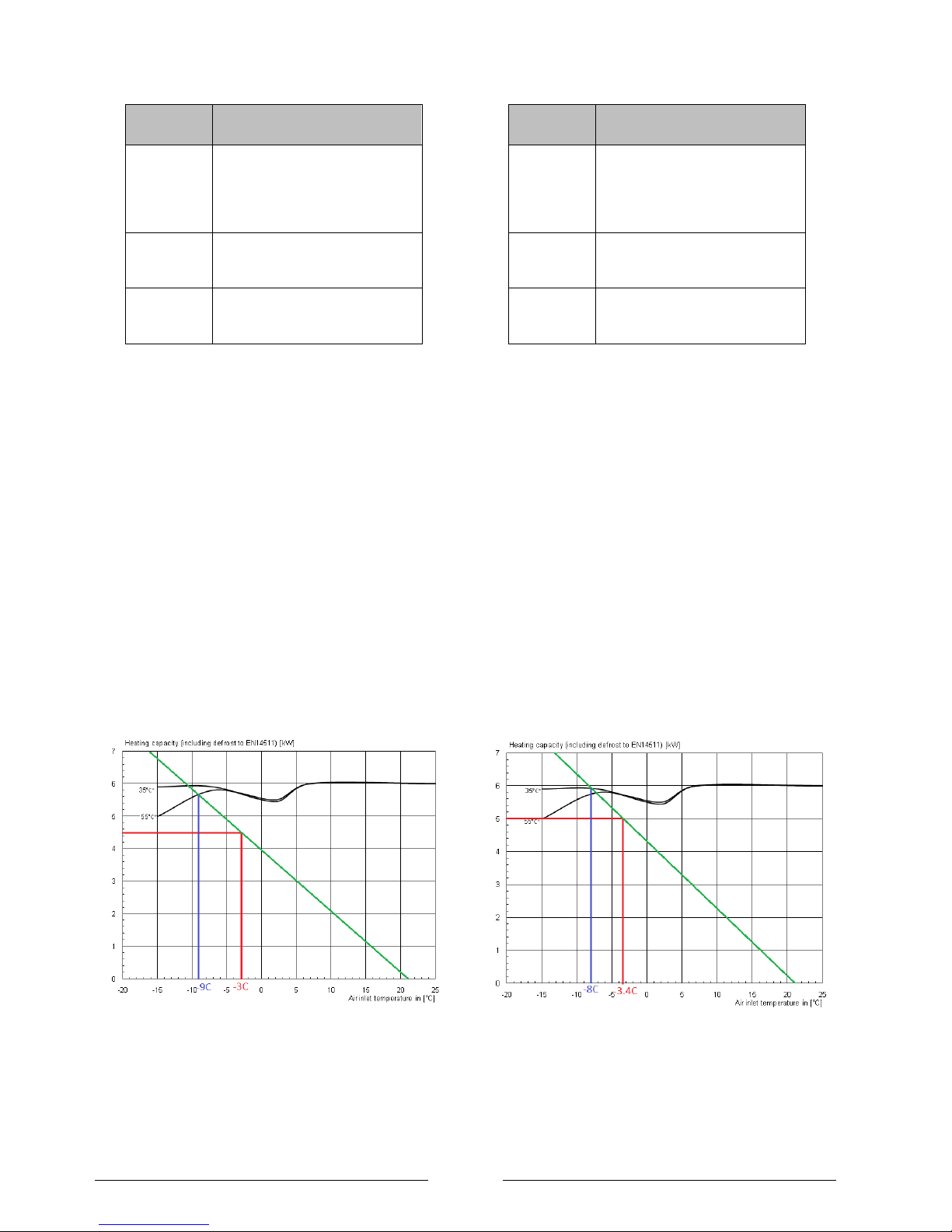
The heat pump is dimensioned on the heat consumption
of the building at the design temperature as shown in
green in Figure 1.
Step 1: The building's heat loss is plotted based upon the
0kW @ 21C and the building‟s calculated heat loss at the
design temperature i.e. 4.5kW @ -3C as shown by the
green line.
Step 2: At the point where the green line crosses the
performance line of the heat pump the blue line can be
drawn to show the external temperature that the heat
pump will be able to match the heat load of the property
which in Figure 1 is -9C.
Step 3: Below external temperatures of -9C the property
will require additional heat. The factory fitted 3kW inline
flow boiler in addition to the 6kW heat pump to gives 9kW
which will support the properties heat load down to the
operating limit of the heat pump which is -20C.
Figure 1: Example heat output curves to EN14511
for the LA 6 MI for a heat loss of 4.5kW at a design
temperature of -3
C.
Sizing example 2
Design
temperature
The property is in Birmingham,
England – NHBC recommend
3C and MIS 3005 recommend -
3.4C. The design temperature is
therefore -3.4C.
Building
heat loss
The properties heat loss is
calculated to be 5kW at the
design temperature.
Flow
temperature
Has been selected at 35C as
under floor heating is going to be
used.
The heat pump is dimensioned on the heat consumption
of the building at the design temperature as shown in
green in Figure 2.
Step 1: The building's heat loss is plotted based upon the
0kW @ 21C and the building‟s calculated heat loss at the
design temperature i.e. 5kW @ -3.4C as shown by the
green line.
Step 2: At the point where the green line crosses the
performance line of the heat pump the blue line can be
drawn to show the external temperature that the heat
pump will be able to match the heat load of the property
which is also 5.9kW at –8C.
Step 3: Below external temperatures of -8C the property
will require additional heat. The factory fitted 3kW inline
flow boiler in addition to the 6kW heat pump to gives 9kW
which will support the properties heat load down to the
operating limit of the heat pump which is -20C.
Figure 2: Example heat output curves for the LA 6 M for a
heat loss of 5.0kW at a design temperature of -1.8C and a the
building heat loading being met down to -15C.
Page 12
Page 11
Section 3: System controls in a domestic setting
Boiler inter lock
The Domestic heating compliance guide sets out the best
practise for preventing energy wastage by preventing
unnecessary running of the circulation pump and heat
pump.
Figure 3: Extract from Domestic Heating compliance guide,
V1 April 2006
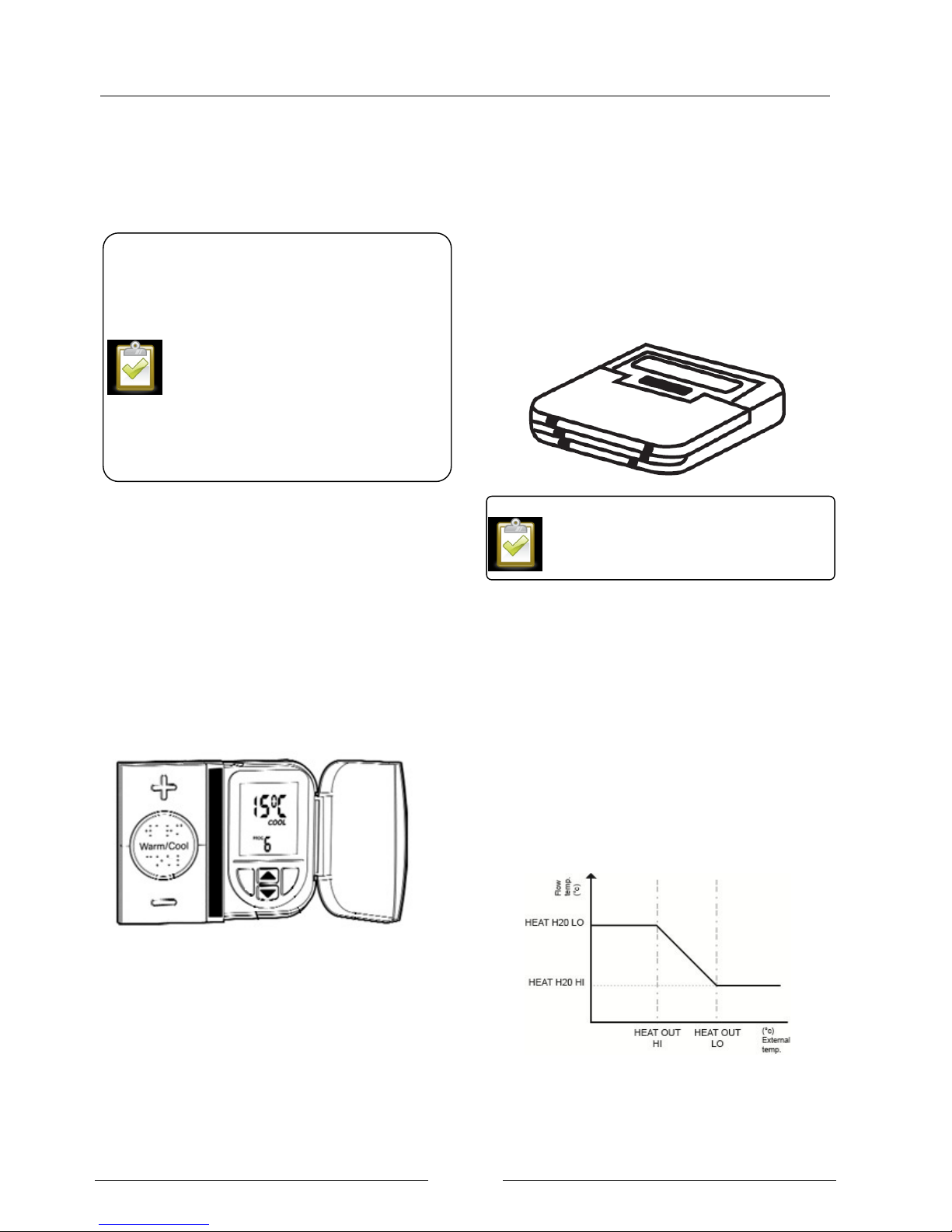
Horstmann PRT thermostat
The LA MI range of heat pumps achieves boiler interlock
using the PRT thermostat.
Supplied by Horstmann, the mains powered thermostat is
designed to provide an economical but comfortable
pattern of heating without the need for complex
adjustments by the user. With built in minimum room
temperature protection this thermostat is ideal for use with
heat pumps because it maintains a base level of heat.
For day-to-day use only the 3 large buttons on the front of
the thermostat are required. The centre „WARM/COOL‟
button, complete with Braille markings, changes the
temperature state and the „+‟ and „-„ buttons provide fine
user adjustment as well as audible feedback. Each user
adjustment is immediately reflected in changes to the
bright red and blue LED display.
Using a variety of pre-installed heating profiles that can be
easily set up by the installer, and a minimum cool setting
of 15C, the ThermoPlus aims to provide maximum
comfort to the user and prevent hypothermia and keep a
level of background heat. Under the flap the blue standby
button will put the control into „frost protection‟ mode until
reactivated.
Heat Pump Controller
The heat pump‟s safe and efficient operation is regulated
by the built in controller. The remote panel can be
connected via the 15m cable meaning allowing the user to
adjust the heat pump settings.
Weather compensation
The highest flow temperatures are only required during the
coldest weather. As the external temperature increases,
the heat loss of the build decreases which means that the
heat emitters no longer have to work at their maximum
output in order to keep the building at the correct
temperature.
The LA MI is fitted with a weather compensation curve as
shown in Figure 4. The curve can be adjusted depending
on the system characteristics. By activating weather
compensation it ensures the heat pump is always
operating at the minimum flow temperature and therefore
the maximum efficiency.
Figure 4: Weather compensation curve on the LA MI
Recommended controller settings can be
found in the installation instructions. An
explanation of how to set the controller can be
found in the programming overview document.
External controls should include:
Room thermostat to regulate the space
temperature and interlocked with the heat
pump unit operation.
Timer to optimise operation of the heat
pump
An interlock is defined as “controls which are
wired so that when there is no demand for
either space heating or hot water, the boiler
and pump are switched off.
The use of Thermostatic radiator valves
alone does not provide interlock.
Page 13
Page 12
Section 4: Selection of heat emitters and flow temperatures
Minimising the flow temperature
In most oil and gas boiler systems the efficiency doesn‟t
vary greatly with flow temperature, therefore the flow
temperature is set to around 70°C to 75°C. The high
temperatures are not always required as downstream
regulator such as mixing and thermostat valves, prevent
the building from overheating.
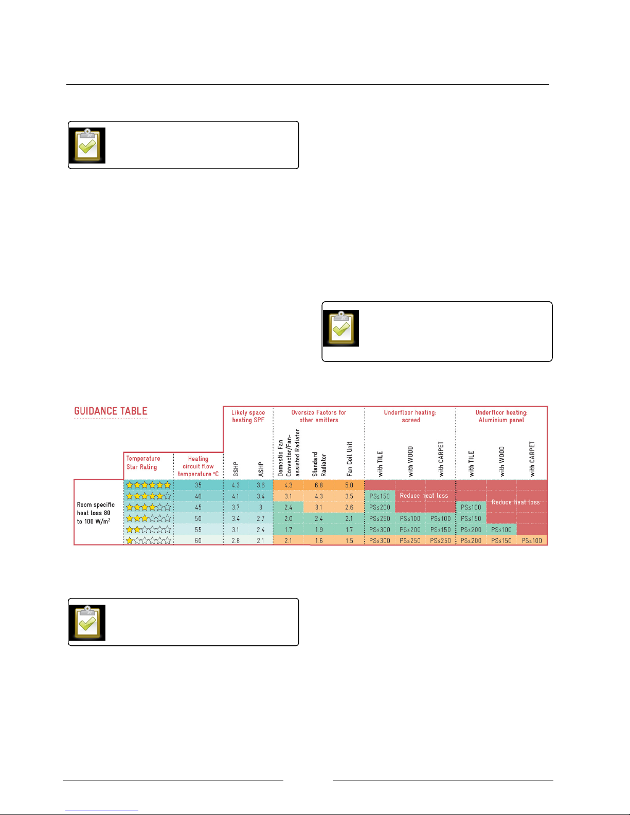
To design the most efficient heat pump system it is
essential to minimise the flow temperature. When using
low flow temperatures the choice of heat emitter is critical
to ensure enough heat can be emitted into the room. A
number of industry stakeholders have produced a guide to
selecting the correct heat emitter, an extract of which is
shown in Figure 5. The full guide is available for download
from HHIC website. The guide shows that systems with
lower flow temperature achieve the highest SPF‟s which
would reduce running costs and carbon emissions.
Green areas show suitable heat emitters
Example: a domestic fan convector such as a
SmartRad can be installed with a flow temperature of
45C.
Orange areas show that extra caution is advised
Example: standard radiators should not be installed
with a flow temperature of 60C as a flow
temperature of 50C would give the necessary output
without causing the radiator to become excessively
large.
Red areas show that this technology is not suitable
Example: under floor heating on a screed floor with a
wood covering would not emit enough heat into the
room with a flow temperature of 45C.
Figure 5: Extract from the HHIC's guide to heat emitter selection for a heat loss of 80W/m2
Considerations for fan convectors
The benefits of installing SmartRad with a heat pump
system are well known and explained in the SmartRad
planning manual. This selection deals with connecting
SmartRad with the LA MI range of heat pumps.
When connecting the SmartRad the same principles
should be followed as for any other heat emitter. The
minimum flow rate for the heat pump should be observed.
The heating circuit should be designed in such away to
maintain the flow to the heat pump even when the part of
the circuit is shut off by motorised valves or the heating
circulation pump is off.
For full details about connecting SmartRad
to an inverter air source heat pump see the
SmartRad planning manual.
The Heat Emitter Guide is widely available to
download on the internet. Hard copies are
available upon request by contacting the
MarComs team at Dimplex.
As a rule of thumb, by lowering the flow
temperature by one degree, the system
performance will improve by 2%.
Page 14
Page 13
Section 5: DHW preparation with inverter heat pumps
Dimplex EC-Eau cylinder range
EC-Eau, the new range of unvented stainless steel
cylinders from Dimplex can supply all the hot water
required for the modern home, providing rapid fill baths
and invigorating showers to en-suite bathrooms and
other domestic appliances simultaneously. Offering low
running costs, reliable hot water and fantastic flow
rates, EC-Eau cylinders are available in a range of
capacities, so there is size to suit even the most
demanding household.
EC-Eau heat pump cylinders are specified with large,
high surface area heat exchangers, specifically sized to
match the requirements of Dimplex heat pumps,
optimising heat pump efficiency and reducing running
costs. The diameter of the EC-eau range has been
specifically picked for the UK market with a diameter or
580mm unlike many other cylinders available.
Supplied with an external expansion vessel for
improved reliability and reduced cylinder height, ECEau standard cylinders are flexible to site and easy to
install.
Environmental sensitivity and efficient performance are
key attributes across the EC-Eau range, which boasts
60mm of low GWP insulation foam and innovative
measures such as recessed immersions and
thermostats to reduce energy wastage. This combined
with the use of 100% recyclable stainless steel inner
components and a sleek black, hard wearing outer shell
manufactured from completely recycled materials
ensures the EC-Eau range looks as good as it
performs.
Dimplex ECS Combination DHW and Buffer
Cylinders
In addition to all the benefits of the standard cylinder
Dimplex can also offer a combination cylinder with a
DHW cylinder and buffer cylinder. This makes is easy
to retrofit a heat pump as the new combination cylinder
takes up the same space as the old cylinder.
The EC-eau range of combined buffer and DHW
cylinders have the buffer cylinder on top which gives
the following benefits:
The buffer acts as an excellent air separator,
and putting at the top of the cylinder means it
is likely to be one of the highest points in the
system allowing air to easily be removed.
The heat loss is reduced from the combination
cylinder because there is less of a temperature
gradient between the cylinder/buffer compared
to the cylinder/ambient air.
Volume
Outer
diameter
Cylinder
only
Combined
buffer and
cylinder
125
580mm
150
580mm
175
580mm
210
580mm
250
580mm
300
580mm
Table 7: EC-eau cylinders for use with the LA MI range
Heat pump power for hot water preparation
In addition to the space heating, the demand placed on
the heat pump for hot water production must be taken
into account when selecting the heat pump.
To meet normal comfort requirements, a peak hot water
consumption of approximately 60-70 litres per person,
per day, should be allowed, based on a hot water
temperature of 45°C.
Selecting a DHW cylinder
A standard DHW cylinder is not suitable for use with
heat pumps due to the small coil size. A heat pump
provides lower hot water temperatures compared to a
boiler. For this reason a heat pump cylinder needs a
larger coil to ensure that the heat can be transferred
from the heat pump in to the water within cylinder as
efficiently as possible.
For all heat pumps, the achievable cylinder temperature
is affected by the maximum flow temperature and also
the kW output of the heat pump. Since the kW heat
output of an inverter air source heat pump does not rise
with air temperature the LA MI heat pump can achieve
45°C in all of the cylinders shown in Table 8.
If a different cylinder temperature is required the
following must be taken into account. For each of
Dimplex‟s heat pump cylinders, a graph of kW input vs
The sizing should be based on the worst
day, with the coldest possible weather and
the maximum possible number of persons
using DHW. If this sizing method is not
suitable because it causes over sizing of the
heat pump, the end user should be made
aware that they may sometimes need to use
the immersion DHW boost which can be
activated from the wall mountable heat pump
controller.
Page 15

Page 14
attainable cylinder is published. In conjunction with the
published information of the minimum output at
A25/W55 for each heat pump the attainable cylinder
temperature can be found.
The flow rate though the cylinder coil is an important
factor in determining the achievable cylinder
temperature. The hydraulic resistance of the coil and
connecting pipe work must be checked to ensure that
the circulation pump pre-installed in the LA MI is able to
achieve the necessary flow rate.
Heat Pump
Cylinder model
45C achievable
with correct flow
rate
LA 6 MI
(Flow rate 1.0m3/h)
ECS125HP-580
Yes
ECS150HP-580
Yes
ECS175HP-580
Yes
ECS210HP-580
Yes
ECS250HP-580
Yes
ECS300HP-580
Yes
LA 9 MI
(Flow rate 1.6m3/h)
ECS125HP-580
Yes
ECS150HP-580
Yes
ECS175HP-580
Yes
ECS210HP-580
Yes
ECS250HP-580
Yes
ECS300HP-580
Yes
LA 12 MI
(Flow rate 2.1m3/h)
ECS125HP-580
Yes
ECS150HP-580
Yes
ECS175HP-580
Yes
ECS210HP-580
Yes
ECS250HP-580
Yes
ECS300HP-580
Yes
LA 16 MI
(Flow rate 2.8m3/h)
ECS125HP-580
Yes
ECS150HP-580
Yes
ECS175HP-580
Yes
ECS210HP-580
Yes
ECS250HP-580
Yes
ECS300HP-580
Yes
Table 8: Cylinders suitable for use with the LA MI range
with an external temperature up to 25°C.
Cylinder volume and reheat
The amount of stored hot water should be adequate to
meet the demands of the property. The installer should
gauge the likely hot water use depending upon the type
of showers, baths and taps installed within a short time
and select an appropriately sized cylinder.
It should be noted that the cylinder reheat times will be
longer with a heat pump compared to a typical gas
boiler. This is because a gas boiler is often drastically
oversized compared to the space heating requirement
whereas a heat pump is sized much closer to the heat
pump. For this reason, it may be necessary for a heat
pump cylinder to be larger than a cylinder installed with
a gas boiler.
Heat pump output
6kW
9kW
12kW
16kW
ECS125HP-580
44
29
22
16
ECS150HP-580
52
35
26
20
ECS175HP-580
61
41
31
23
ECS210HP-580
73
49
37
27
ECS250HP-580
87
58
44
33
ECS300HP-580
105
70
52
39
Table 9: Calculated cylinder reheat time with different heat
pumps
Cylinder replacement
In addition to the instructions supplied with the cylinder,
when planning on replacing an old vented cylinder for a
new unvented stainless steel cylinder it is important
check the following:
The water main is capable of supply adequate
pressure and flow rate at all times of the day.
The fittings such as taps and valves are
suitable for the new higher pressure system.
Selecting and controlling the DHW
temperature
The heat pump controller monitors the temperature in
the DHW cylinder via a sensor and decides when to
work in hot water mode. The user can set the time of
DHW production and also the temperature of DHW
product using the wall mountable controller.
It is important that the customer understands
that the maximum flow temperature out of the
heat pump is higher than the maximum
attainable temperature in the cylinder.
If a heat pump is being installed on to an
existing property it is likely that the old hot
water cylinder will have to be replaced with a
new one with a larger coil.
Page 16
Page 15
For efficient operation the DHW temperature should be
set to 45°C. Experience has found that this is more
than hot enough for showering and bathing.
If required, the hot water temperature can be set up to
75ºC although this will utilise the immersion heater for
some of the heating period. By raising the storage
temperature, the volume of usable water is increased
which is useful is properties where a larger cylinder
can‟t physically be fitted.
The maximum temperature that the compressor can
achieve before the immersion needs to finish the
demand is variable based upon a number of factors. In
practice the LA MI heat pump is able to reduce its kW
output using the inverter compressor and can also
maintain its output above 55ºC for a short period of
time.
It is therefore, not uncommon for the LA MI to achieve
cylinder temperatures of 50ºC using only the
compressor. It should however be noted that other
factors within the system can reduce the attainable
cylinder temperature so the customer expectation
should be managed to expect their hot water to be
stored at 45ºC.
The adjustable dial on the cylinder thermostat is not
wired in or used because the temperature of the
cylinder is controlled by a sensor. A notice such as that
shown in Figure 6 should be attached next to the
cylinder thermostat.
Figure 6: Notice to be fixed next to cylinder thermostat
Note that the manually resettable high temperature cutout in the cylinder thermostat is wired back to the heat
pump for G3 protection.
Sterilisation
For Domestic properties there is no official guidance on
the correct storage temperature or if thermal
sterilisation is required. There is a theoretical risk of
legionella growth, although no cases have yet been
reported in a domestic hot water system.
There is a trade off between maximising system
efficiency by reducing energy consumption and
minimising the theoretical risk of legionella growth. The
risk of legionella growth can be minimised by ensuring
that the cylinder does not remain stagnant for long
period of time. If the property is not occupied for a long
period, upon reoccupation, it would be prudent to raise
the cylinder temperature to 60°C and open the water
outlets to allow the connecting pipe work and outlets to
be sterilised.
For private domestic properties, Dimplex recommend
that the cylinder is raised to 60°C once per week
although the ultimate decision lies with the householder
to weight up the risk with the energy saving benefits.
For commercial properties the legislation requires for
the water to be stored at 60C.
Secondary circulation pipes
A secondary circulation pipes is used to continuously
pump hot water around a closed loop, so that there is
not a long period of time from the taps opening to the
hot water being available. All of the EC-eau range of
cylinders larger than 210L feature a boss for connection
of a secondary return.
Heat consumption for a circulation pipe can be
considerable. The increase in consumption depends on
both the length of the circulation line and the quality of
the pipe insulation and on a large system should be
taken into account to ensure the heat pump is suitably
sized.
To maximise the efficiency of the system, if a circulation
system cannot be dispensed with because of long pipe
runs, the circulation pump should operate on a timed
basis.
The water drawn off immediately after
sterilisation will be much hotter than usual.
Consideration should be given to installing
a temperature limiting device at the outlets
to prevent scolding.
The schedule for sterilisation should be
determined by the installer to comply with
the necessary regulations.
TEMPERTURE ADJUSTMENT
The temperature of the hot water in this
cylinder is set using the wall mounted heat
pump controller. The setting shown on this
thermostat does not affect the hot water
temperature.
Setting the hot water temperature higher
than the heat pump alone can do with the
compressor would cause the immersion to
It is important to explain to an end user about
the correct cylinder temperature for economic
operation of the heat pump. They may have
previously been used to scolding hot
temperature that they mixed with cold water.
Page 17
Page 16
Section 6: Installation considerations
When deciding the location to install the heat pump the
items contained within this chapter should be considered.
Physical location
The heat pump is for outdoor installation only. It should
also be installed in a place where:
The condensate can easily be drained away.
Hydraulic connections can easily be made to the
heating system and the DHW cylinder.
There is no risk of a flammable gas leak or any
outlets vents from any other system.
The wiring lengths come within reasonable
ranges particularly taking note of the 15m
controller cable.
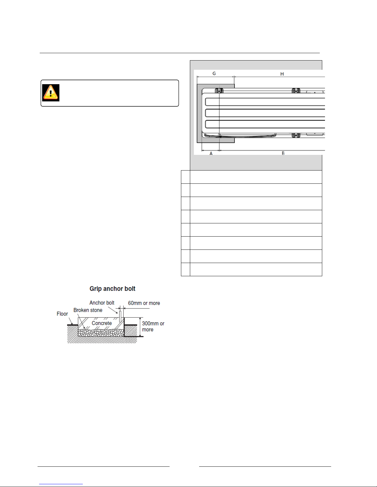
Fixing of the heat pump
The heat pump should be fixed on two flat, horizontal and
solid hard surfaces such as concrete pads that are
capable of taking the unit‟s weight and draining the
condensate.
To prevent tipping, the heat pump must be suitably fixed.
The fixing should be strong enough to prevent the unit
from tipping over if the base becomes unlevel over time.
Suggested dimensions of concrete pads as shown in
Figure 7.
A
152 B 1002
C
300
D
356 E 400 F 520 G 400
H
600
When installing the product in a place where it will be
affected by strong wind such as wind blowing between
buildings or on a rooftop an overturn prevention wire
supplied by the installer may be necessary.
Wall mounting
If the heat pump is to be wall mounted a condensate
collection tray (supplied by the installer) should be fixed
under the heat pump. The pipe from the tray to a suitable
drain should be heated so that it can‟t freeze and become
blocked.
The installation of an air source heat pump
should be carried out by a Dimplex Accredited
installer.
Page 18
Page 17
Figure 7: Top view of two concrete mounting blocks that allow the condensate to drain away via a gravel soak away.
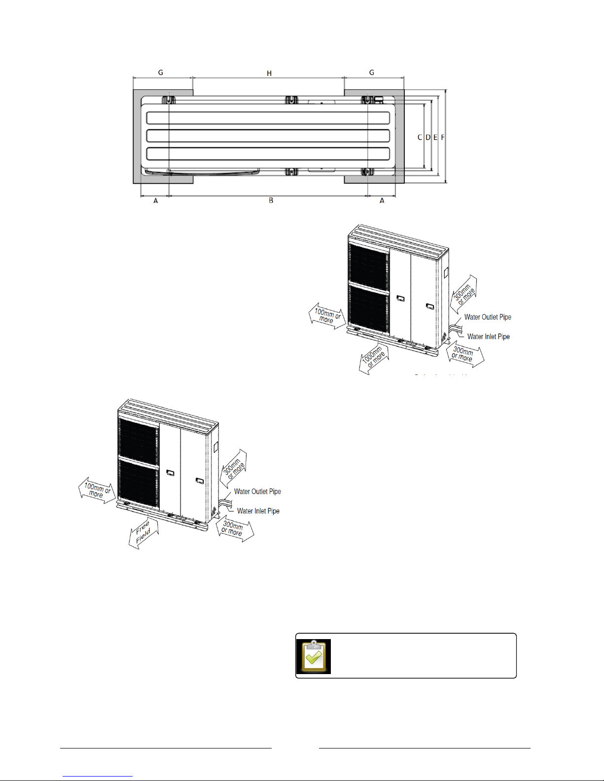
Ventilation
The installation site must be an open location clear of any
obstacles which may cause a short circuiting of the
discharged air or increased resistance due to blocking of
the inlet or outlet. This includes walls and fences as well
as locations prone to blocking debris such as leaves or
snow.
Avoid installing the heat pump in a location where suction
side of the fan may be exposed directly to wind. If the
location is in open ground, the heat pump should be set
up so that the air outlet direction of the fan is
perpendicular to the main wind direction to allow
unrestricted defrosting of the evaporator.
Figure 8: Minimum distances to objects to ensure adequate
ventilation
Minimum maintenance clearances
It must be possible to carry out maintenance work without
hindrance the displayed in Figure 9 should be observed.
For example if the unit is installed on a balcony there must
be a space measuring 1000mm in front of the unit of
maintenance.
Figure 9: Minimum clearances for maintenance (not
including clearance for air circulation)
Sound insulation measures
The installation may also have to comply with the MCS
020 standard as detailed in the section on the next page.
Furthermore, the heat pumps should be installed in a
location considering the following:
the occupant‟s enjoyment of the garden and
outside spaces.
any windows that open close to the heat pump.
The effect on neighbouring properties.
The lowest noise emissions are achieved if an area of 35m surrounding the heat pump does not have any hard
surfaces that can reverberate the sound. Additionally, the
foundation can be covered up to the level of sledge on the
heat pump with sound-absorbing material such as bark,
plants or grass. These must not affect the air flow or and
care must be taken so they don‟t get sucked into the fan.
If the heat pump is installed above inhabited
rooms, measures to prevent solid-borne
sound should be considered.
Page 19
Page 18
Air quality
If heat pump is subject to any of the following substances
in the air its‟ life span will be shortened and the guarantee
may not be valid. If the air contains any of the following,
please contact Dimplex for further information:
Sulphur i.e. Near a busy congested road.
Oil i.e. a workshop.
Ammonia i.e. animal stables
Salt i.e. near the sea.
The above conditions will affect all the exposed
components within the heat pump, but especially the
evaporator. Dimplex offer an extra service to coat the
evaporator with a protective coating. This additional
service adds a week to the delivery times. For more
details contact the Dimplex technical team.
Local planning regulation
MCS Planning Standard
The MCS planning standard sets out the method by which
to calculate if the installation would meet the noise limit of
42bB. If the assessed noise level is greater than 42dB the
installation may only still go ahead if planning permission
is granted by the local authority. The value of the noise
level at the assessment position is affected by:
The A weighted sound power level of the heat
pump as given in the technical information
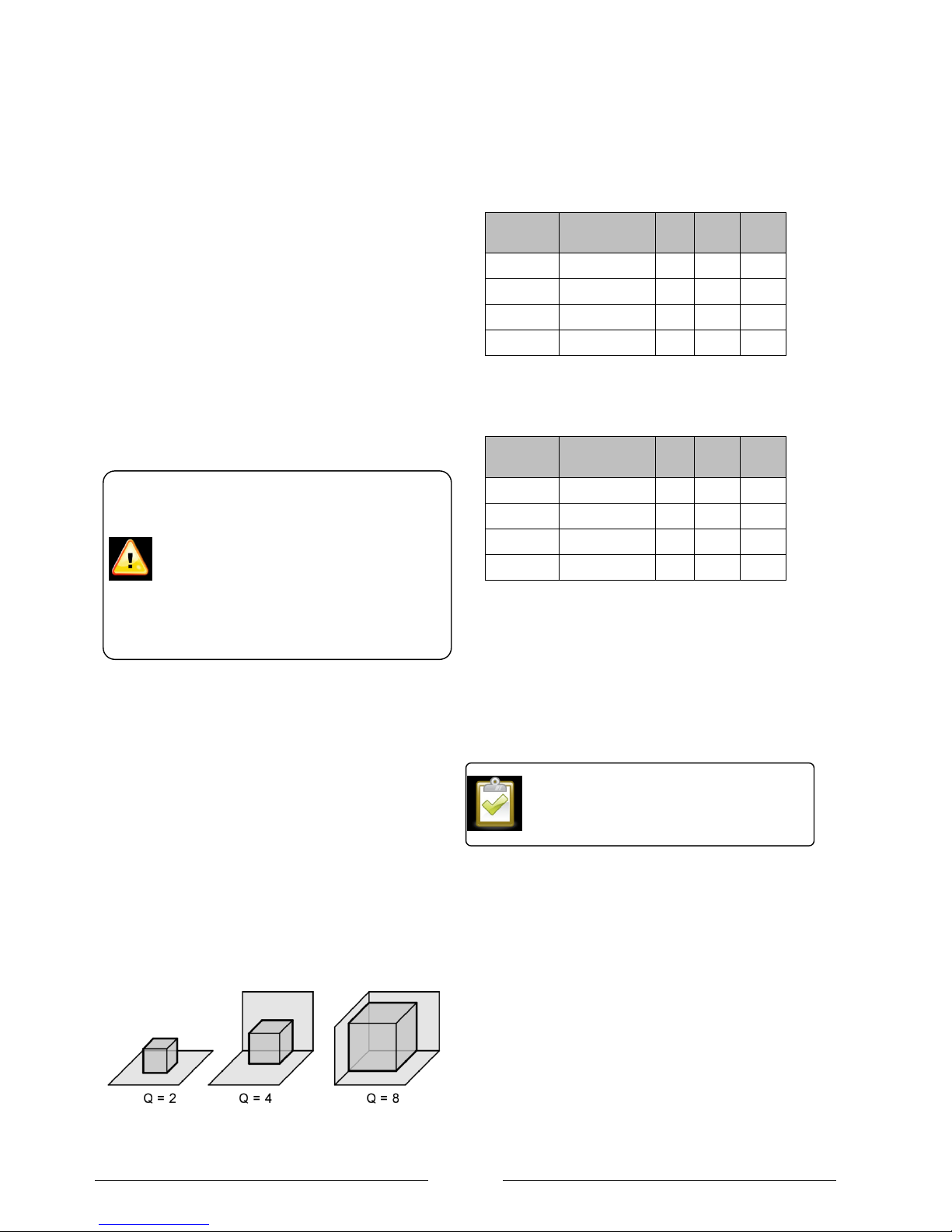
The directivity Q factor as determined by the
number of walls as shown in Figure 10.
The effect of solid barriers between the heat
pump and the assessment position.
The back ground noise level.
Figure 10: Q factors for different surfaces within 1 meter of
the LA MI.
Table 10 and Table 11 show the minimum distance to
achieve the 42bB at the assessment position in the MCS
020 calculation.
A weighted
sound power
level
Q2
Q4
Q8
LA 6 MI
58.0dB(A)
2m
2m
3m
LA 9 MI
61.5 dB(A)
2m
3m
4m
LA 12 MI
62.0dB(A)
2m
3m
4m
LA 16 MI
64.0dB(A)
3m
4m
5m
Table 10: Minimum distances to achieve 42dB if there is a
wall between the heat pump and assessment position
A weighted
sound power
level
Q2
Q4
Q8
LA 6 MI
58.0dB(A)
4m
6m
8m
LA 9 MI
61.5 dB(A)
8m
10m
15m
LA 12 MI
62.0dB(A)
8m
10m
15m
LA 16 MI
64.0dB(A)
8m
12m
20m
Table 11: Minimum distances to achieve 42dB if there is NOT
a wall between the heat pump and assessment position
Compliance with the MCS Planning Standard on its own
does not bestow permitted development rights – there are
a number of other conditions and limitations which must
be complied with for an installation to be permitted
development, some of which are detailed below.
Town and Country planning, England
The following is a summary of the main points for an Air
source heat pump under the Town and country planning
act. The installer should consult the original document for
further clarification and a full list of points. The act states
that planning permission would be required if the:
Installation doesn‟t comply with the MCS
planning standard.
Installation would result in more than one air
source heat pump on or within the grounds of
the building.
Site already has a wind turbine.
For further information see the MCS document
020, “MCS Planning Standards For permitted
development installations of wind turbines and
air source heat pumps on domestic premises.”
Every effort has been made to give accurate
advice on local planning regulations for
England, Wales and Scotland. The following
information is provided with the intension of
making the installer aware that such
regulations exist rather than a definitive guide.
It is essential that the installer verifies the
regulations with the local planning office
before proceeding with the installation.
Page 20

Page 19
Heat pump will be within 1m of the property
boundary.
Heat pump is installed on a pitched roof or 1m
from the edge of a flat roof.
Proposed site is a scheduled monument, listed
building, conservation area or world heritage
site.
Installed on a wall or roof which fronts the
highway
Heat pump ss closer to the road than the
property
The heat pump is installed above the level of the
ground storey.
The heat pump is used solely for heating
purposes.
external unit is greater than 0.6 m3 in size (all LA
MI units pass this test)
Planning in Wales and Northern Ireland
Air source heat pump installations in Wales and Northern
Ireland require planning permission as there are no
permitted development regulations.
For further information see the “Town and
Country Planning (General Permitted
Development) (Amendment) (England) Order
2011, No. 2056”
Page 21

Page 20
Town and Country planning, Scotland
A domestic installation of an air source heat pump in
Scotland will be classed as a Permitted Development,
unless:
It would result in the presence within the curtilage
of a dwelling of more than one air source heat
pump
The air source heat pump would be situated less
than 100 metres from the curtilage of another
dwelling
The air source heat pump is visible from the road
in a conservation area or would be within a World
Heritage Site or the curtilage of a listed building.
In addition, before beginning the development the
developer must apply to the planning authority to:
determine whether the prior approval of the
authority will be required for the siting and
external appearance of the air source heat pump
Find out if the application needs to be
accompanied by a range of other information and
a if any number of other conditions apply.
For further information see the “The Town and
Country Planning (General Permitted
Development) (Domestic Microgeneration)
(Scotland) Amendment Order 2010, No. 27.”
Page 22

Page 21
Section 7: Heating System Connection
External pipe work
The pipe work running from the heat pump into the
property should be sufficiently insulated to minimise
the heat loss and consideration should be given to
using the correct material.
Minimum water volume
The minimum water volume of the system is 50 litres
which must always be available when in heating mode
even if all of the zone valves are closed and additional
circulation pumps are off. This is typically achieved by
installation of a buffer cylinder. If a buffer cylinder is
not present there may be problems during a defrost,
namely the heating distribution system going cold and
electric immersion being required to bring it up to
temperature.
The internal volume of the heat pump is 5L.
Buffer tank
The integration of an air-to-water heat pump requires a
buffer tank connected in series to ensure that the
evaporator (finned heat exchanger) is defrosted by
means of reverse circulation. Installation of a buffer
tank connected in series also lengthens the runtimes
of the heat pump during periods of reduced heating
demand.
Minimum heating water flow rate
performance data table‟ must be observed. The
following factors should be considered:
Hydraulic resistance of the pipe work. Special
attention should to given to ensure the correct
pipe diameter is chosen considering the
required flow rates.
As a rule of thumb 28mm pipe work should be
used although the sizing of the pipe work
remains the responsibility of the installer.
To minimise energy consumption the pump
should run of the lowest speed possible whilst
still achieving the correct flow rate. The
resistance of all the pipe fittings, filter, heat
emitters and condenser must be taken into
account.
Failure to observe the minimum water throughput will
cause the heat pump not to work due to operation of
the flow switch alarm (H62).
The maximum water throughput is 20% more than the
stated minimum water throughput. Exceeding the
maximum flow rate would result in an inefficient
system operation due to increased pumping losses.
For systems in which the heating water flow can be
shut off via actuators or thermostatic valves an
overflow bypass valve must be installed to guaranteed
to minimum water flow rate.
Taconova flow checker
The Taconova flow checker is provided in every
system package to provide a simple way to verifying
that the flow rate is correct. The flow rate is read on
the bottom of the spinner as shown in
Figure 11: Correct reading of flow rate on the taconova
flow checker
The flow checker should be installed in a visible
location inside the property and as close to the heat
pump flow as possible. In order given an accurate
reading the pipe installation distances shown in Figure
12 should be observed as well as the flow direction as
shown in Figure 13.
When connecting the heating system, all
applicable regulations must also be adhered
to including all relevant European and
national regulations (including EN61770), and
local building regulation codes.
Work that requires the covers to be removed
must only be carried out under supervision of
qualified contractor, installation engineer or
service person.
The installation of an air source heat pump
must be carried out by a Dimplex Qualified
installer.
Page 23

Page 22
It is important to install the flow checker on the flow
pipe so it is protected from impurities within in the
system via the filter on the heat pump return.
Figure 12: Minimum straight pipe distance before entrace
to Taconova unit
Figure 13: Ensure the flow rate through the Taconova is
in the same direction as the arrow
Plumbing connections
Model
Fitting size
Torque
LA 6 MI
1 ¼” male flat face
118 Nm
LA 9 MI
LA 12 MI
LA 16 MI
Table 12: Water connections on LA MI
Frost protection
So long as the heat pump is connected to the mains
electrical supply the automatic antifreeze function will
prevent the water in the pipes freezing during cold
weather.
In case of a prolonged power supply failure or a
circulation pump failure the system must be drained
using the screws on the flow and return connections.
When water is idle inside the system, freezing up is
very likely to happen which could damage the system
beyond economic repair.
The installer should conduct a risk assessment to
determine the likelihood of water freezing in the heat
pump and interconnecting pipe work in the event of a
power failure during cold weather. The heating circuit
should be dosed with suitable antifreeze if heat pump
system is in a building where a power failure cannot be
detected or the occupants would be unable to drain
the system. If antifreeze is used the concentration
should be large enough to prevent freezing for the
coldest local temperature and the installer should
ensure the glycol is vented to a suitable place to
prevent contamination of the environment or sewage
system in the event the pressure relief valve activating.
Condensate
During normal operation the heat pump will remove
water vapour from the air. The condensate will run
down the evaporator into the condensate tray where it
will drain out of the unit. Defrosting takes place up to
16 times per day, with up to 3 litres of condensed
water being produced each time.
Condensed water that forms during operation must be
drained off frost-free. The heat pump must be mounted
on a level surface to guarantee proper drainage. The
condensate such drain onto a surface such as gravel.
If a tray is used to funnel the condensate, the drainage
pipe must have a minimum diameter of 50mm and
should be fed into a frost free trap and then a sewer for
rain water to ensure that large quantities of water can
be drained off.
Flushing the system
It is advisable to fit specific connections for flushing
and filling as shown in the plumbing schematics.
Before connecting the heating water system to the
heat pump, the heating system must be flushed to
remove any impurities and residue from sealants, etc.
Any accumulation of deposits in the condenser could
reduce the heat pumps performance. Do not use worn
out piping that may have become blocked over time.
Ensure that impurities are not flushed though
the heat pump since they could block the
channels in the condenser.
The condensate must drain on to an surface
that is freely draining. It must not drain on to
footpaths or patios as it could refreeze and
become a hazard.
Page 24

Page 23
Filter
It is essential to install a filter immediately before the
water inlet to the heat pump. Not installing this filter
would invalidate the warranty of the heat pump as
debris can easily block the condenser channels.
The MFK114 isolation valve as shown in Figure 14 is
included in the heat pump packages. The valve can be
closed and the filter removed and checked without
having to drain the system.
Figure 14: Isolation valve and filter supplied in LA MI
packages to be fitted to the heat pump return.
Figure 15: Isolation valve supplied in package to be fitted
to the heat pump flow.
Filling the system
The system should be filled with potable water. The
system water should be treated with standard central
heating inhibitors.
The cold fill gauge pressure on the heat pump should
be between 0.8 and 1.5 bar (0.08-0.15MPa). This will
rise during normal operation.
De-aeration
Air trapped in the system causes air locks which in turn
cause poor water flow around the system. Every high
point in the system should have a means of bleeding
out air which is supplied by the installer.
The pressure relief valve shown in Figure 17 can be
used to purge the air from the heat pump during filling.
Figure 16: Location of pressure relief valve
Figure 17: Pressure relief valve
Adjusting the water flow rate
The default setting is moderate speed (III). The
circulation pump must be adjusted to give a suitable
flow rate to maximise system operation. The heat
pump should be turned on and the compressor
allowed to reach maximum frequency. Once this
frequency is reached the pump speed should be
adjusted so the difference between the flow and return
is as close to 5C as possible. If the difference is
greater than 7C this would potentially cause nuisance
tripping of the flow alarm.
Expansion vessel sizing
The heat pump comes with an expansion vessel
installed as shown in Table 13. Dependant on the
static height of the system and the volume it may be
necessary to install a second expansion vessel.
Depending upon the specific system the
installer must determine if a second
expansion vessel is required.
Page 25

Page 24
Expansion
vessel size
Pre-charge
LA 16 MI
10L
1 bar
LA 12 M
LA 9 MI
6L
LA 6 MI
Table 13: Size of expansion vessel in the LA MI range
For most installations the 10L expansion vessel should
be able suitable with a volume up to 200L and a static
height of 7m. The 5L expansion vessel should be
suitable for a system volume up to 100L and a static
height of 7m.
2 port valves
The heat pump packages include 2 x F228 Horstmann
two port valves as shown in Figure 18 to switch
between space heating and domestic hot water mode.
Fit the valves ensuring that the actuator head is not
below the horizontal level of the pipe work and that the
flow is in the direction of the arrow. Remember to
make allowances for maintenance and replacement.
Figure 18: Dimensions of F228 valve
Controlling DHW temperature
The cylinder temperature is controlled via an NTC2
sensor.
For safety reasons the heat pump controller also
checks for continuity from the DHW thermostat. The
temperature regulation thermostat and high limit stat
are wired in series. To keep the contacts closed on the
regulation stat the dial must be set to maximum. The
contacts on the high limit stat will remain closed during
normal operation. If the heat pump does not detect
continuity across both the regulation stat and high limit
stat an H91 error will occur.
A label similar to that shown in Figure 6 should be
supplied by the installer and fixed on the cylinder to let
the user know.
Figure 19: Notice to be supplied by the installer and fixed
next to cylinder thermostat
TEMPERTURE ADJUSTMENT
The temperature of the hot water in this
cylinder is set using the wall mounted heat
pump controller. The setting shown on this
thermostat does not affect the hot water
temperature.
For normal operation the dial should be
set to the maximum position.
The thermostat on the cylinder should
not be modified to disable the regulation
stat or high limit stat.
The F228 valves have been specifically
selected for their fast operating times. When
switching from heating to DHW the heat
pump flow must not be restricted. If a
different valve is used, the valve must be
fully open within 6 seconds of being
switched.
Page 26

Page 25
Section 8: Electrical Connection
Routing of cables within the heat pump
To avoid the electrical cables becoming
damaged by sharp edges they must exit
through the bushing located at the right side of
the heat pump.
The cables must be secured using the clamp
on the control board.
Ducting cables
To access the electrical connections only the front right
hand panel of the heat pump outer casing needs to be
removed as shown in Error! Reference source not
found..
Depending upon the installation the heat pump could
have the following cables that it will be necessary to
route from the heat pump into the property.
1. Main power supply cable
2. Heat pump controller
3. Communication cable for 2 way valves, high
limit stat etc, room thermostat.
4. Domestic hot water sensor
5. Domestic hot water immersion heater (booster
heater)
Ducting should be used to ensure that the enclosed
cables are protected from the effects of weather,
mechanical snagging or wear, rodent damage ect. The
ducting should be positioned in such away to ensure
that water will not track along the ducting and into the
heat pump or property.
Figure 20: Correct cable routes though heat pump
For typical wiring and hydraulic
schematics see section 16 at the end of
this document.
When connecting the heat pump to
the power supply, the relevant EN
standards must be complied with.
Any further connection requirements
stipulated by local utility companies
must also be observed. It is important
that the hydraulic connections have
been completed prior to switching on
the power supply.
Page 27

Page 26
Connection of the power supply to the Heat pump
LA 6 and 9 MI LA 12 and 16 MI
Figure 21: Connection of the power supply cable
Main power supply cable
The power connection of the heat pump is made via a
standard 3-core cable. The cable has to be supplied by
the installer and the wire cross-section is to be
selected according to the power consumption of the
heat pump as shown in Table 14. Similarly, the main
circuit breaker (MCB) at the distribution board should
be correctly rated as shown in Table 2.
For maintenance purposes the power supply of the
heat pump must be equipped with an isolating device
in the vicinity of the heat pump. The isolating device
must have a contact gap of at least 3mm. In addition to
the maintenance isolator an automatic 2-pole
automatic circuit breaker should be installed.
The maximum current carried in the supply cable must
be calculated using Table 2 depending upon the how
the heat pump is configured. For example, it is not
always necessary to connect the inline flow boiler. In
other installations where there is no DHW cylinder is
not necessary to connection the DHW immersion.
Every installation will require power to RCCD 1
(compressor and control circuits).
Once the maximum supply current is known the
installer must then supply a suitably rated cable
depending upon the run length and the type of
environment where it will pass.
The heat pump should only be
connected to a permanent mains supply.
Page 28

Page 27
RCCD 1
RCCD 2
MCB
Compressor &
controller
In line flow boiler
+
DHW immersion switched
by heat pump
In line flow boiler
+
DHW immersion switched
by a relay controlled by the
heat pump or no DHW
immersion installed
Total running
current
(Amps)
Suggested
„type C‟
MCB
rating
LA 6 MI
21A
26A
13A
47
50
34
50
LA 9 MI
23A
26A
13A
49
50
36
50
RCCD 1
RCCD 2
RCCD 3
MCB
Compressor
& controller
In line flow
boiler
DHW immersion
switched by
heat pump
DHW immersion switched
by a relay controlled by
the heat pump or no DHW
immersion installed
Total running
current
(Amps)
Suggested
„type C‟ MCB
rating
LA 12 MI
25A
26A
13A
0A
51
63
64
80
LA 16 MI
27A
26A
13A
53
63
66
80
Table 14: Calculation of running current for entire heat pump to size power supply cable and MCB at distribution
board.
Page 29

Page 28
Inline flow boiler
Figure 22: Manual reset on the over Inline flow boiler
The OLP located on the inline flow boiler, as shown in
Figure 22 prevents the water from overheating. Before
manually resetting the cause of tripping should be
rectified. The OLP can be manually reset by:
1. Removing the OLP Cover.
2. Using an insulated tool to gently push the centre
button on the OLP.
3. Replace the OLP cover.
Domestic hot water immersion
The heat pump is capable of switching a 3kW
immersion directly without the need for an additional
relay as shown on the standard wiring diagram.
Depending upon the wiring runs it may be more
suitable that the heat pump switches a relay rather
than the immersion directly as shown in Figure 23.
This would mean that the cable from the heat pump to
the cylinder could have a lower current rating and
therefore, could be combined with the multi-core cable
rather than run a separate cable.
This method is particularly useful in retro-fit
applications where the existing cylinder already had an
immersion heater and high current supply fitted.
If this is the case the installer should supply an inline
fuse rated at an appropriate current for the relay
selected and the maximum current rating of the multicore cable as shown in Figure 23.
Figure 23: Wiring for Heat pump to control DPCO relay to switch supply for immersion
If the inline flow boiler is not wired in the
frost protection function will not fully
function. The circulation pump will run
but no additional heat will be added to
the system by the inline flow boiler. This
increases the risk of the water in the
system freezing.
Page 30

Page 29
Controller cable
The controller cable is connected to the heat pump
controller using the two rectangular plug connectors as
shown in Figure 24. The cable cannot be extended
because this would increase the resistance and
correct operation of the controller cannot be
guaranteed. The cable is 15m long but 1.5m is
required inside the heat pump leaving 13.5m for
routing to the controller. The cable is included with-in
the scope of supply. The power for the controller is
supplied from the heat pump.
Figure 24: Connection terminals on the controller cable
to controller inside the property.
The controller cable is connected to the heat pump via
a short extension lead which protrudes from the heat
pump as shown in Figure 25. The controller cable
connects to the extension cable as shown in Figure
26.
Figure 25: Location of the extension cable for connection
of the 15m controller cable
Figure 26: Terminals of the extension lead and 15m
controller cable
Each end of the controller cable is different.
Make sure you install it the right way around!
Page 31

Page 30
Connection with the system
The following section contains general information
about the communication connections. Full wiring
diagrams and hydraulics for standard systems are
available in Section 16.
Figure 27: Heat pump communication connections
External controller cable
This can be used to remotely put the heat pump in standby mode upon breaking
the connection from an external control device. When in standby the heat pump
frost protection will still be activated. To enable this function a factory fitted jump
lead between terminals 17 and 18 must be removed.
2 x Two way valves
2 x two-way valves are necessary if the heat pump needs to switch mode from
space heating to domestic hot water production.
Booster (Immersion)
heater
This is the immersion heater installed in the DHW cylinder. It immersion can
either be switched directly by the heat pump or a relay can be fitted locally to the
cylinder as shown in Figure 23.
Receiver Cable
The receiver cable is used to communicate a heating demand to the heat pump
from a device such as a wall mounted thermostat.
Connection of the receiver cable is essential to provide „boiler interlock‟ to
comply with building regulations.
Tank OLP
If the heat pump is doing DHW, the over load protection is connected to the
manually resettable high limit stat on the DHW cylinder. Using this connection is
a way of comply with G3 building regulations.
If such connection is deemed unnecessary a jumper must be connected across
these terminals if the heat pump is programmed for DHW production.
Tank Sensor
The tank sensor is essential for DHW production because it monitors the
temperature in the DHW cylinder. The DHW sensor must be an NTC-2. This
sensor is supplied as part of the standard package.
To comply with wiring regulations it might be necessary for the sensor cable to
be different cable from the other communication cables since it is extra low
voltage and the other cables carrying 240V.
Installation of the controller
The controller should be installed:
In a place which is away from direct sunlight
and high humidity.
On a flat surface to prevent warping of the
remote controller and damage to the LCD
screen.
Where the LCD can be easily seen for
operation. (Standard height from the floor is
1.2 to 1.5 meters.)
In a location where the cable can be fed
though the wall or to the surface of the wall
and attached in such a way as not to cause
snagging.
Page 32

Page 31
Section 9: System Health checks
The following items should be verified to ensure
efficient operation of the system:
Heat pump
Check the fan is clear from debris.
No abnormal sound during operation.
Electrical
Power cable is firmly fixed.
Earth wire connection is secure.
RCCB operation is normal.
Supply voltage is correct.
Hydraulic
Water pressure higher than 0.05 MPa.
Pressure relief valve operation is normal.
The filter is clear of debris.
Check entire system for leaks.
Cylinder
Set temperature is correct for efficient
operation.
Check the high temperature cut out stat on
the cylinder immersion and buffer immersion
have not tripped.
Temperature and pressure relief is operating
correctly.
For full maintenance details for the cylinder consult the
relevant instruction manual.
Wall mounted thermostat
Every 2 years, replace the battery on the
Horstmann PRT1
Heating operation normal.
The set temperatures and heating periods are
suitable for the tenants life style.
Heat pump controller
LCD control panel operation is normal.
Enquire if the user is warm enough and
reduce the weather compensation curve to
maximise the heat pump efficiency.
Section 10: Standard packages
To assist with the design and installation of a system
Dimplex have collated wiring and hydraulic schematics
for the following designs:
Package 1 and 2
Heating and Domestic hot water preparation is done
using the heat pump.
2 x two port valves are used to switch between
heating and DHW preparation.
Room temperature is time and temperature
controlled using the Horstmann wall mounted
thermostat. The thermostat will create a demand if
the temperature drops below 15C whilst the system
is off to prevent the base temperature dropping too
low.
DHW temperature and time period is set using the
Heat pump controller.
Package 3
Package for space heating only so no hot water
cylinder is included.
Buffer cylinder is required to ensure minimum
water volume.
Room temperature is time and temperature
controlled using the Horstmann wall mounted
thermostat. The thermostat will create a demand if
the temperature drops below 15C whilst the
system is off to prevent the base temperature
dropping too low.
Never use cleaning agents containing sand,
soda, acid or chloride as these can damage
the surfaces.
Before opening the device, ensure that all
circuits are isolated from the power supply.
Any work on the heat pump may only be
performed by authorised and qualified aftersales service technicians.
Page 33

Page 32
Kits available for selection by installer
Pack 1
Pack 2
Pack 3
1 heating zone and DHW with combined buffer and DHW cylinder
1 heating zone and DHW
with separate buffer and
DHW cylinder
1 heating zone with buffer
tank
PK1LA 6 MI - 125/75
PK1LA 6 MI - 150/75
PK1LA 6 MI - 210/75
PK1LA 9 MI - 125/75
PK1LA 9 MI - 150/75
PK1LA 9 MI - 210/75
PK1LA 12 MI - 150/75
PK1LA 12 MI - 125/75
PK1LA 12 MI - 210/75
PK1LA 16 MI - 125/75
PK1LA 16 MI - 150/75
PK1LA 16 MI - 210/75
PK2LA 12 MI - 250
PK2LA 12 MI - 300
PK2LA 16 MI - 250
PK2LA 16 MI - 300
PK3LA 6 MI
PK3LA 9 MI
PK3LA 12 MI
PK3LA 16 MI
Component parts of kits
LA 6 MI 1 1 1 1 LA 9 MI 1 1 1 1
LA 12 MI
1 1 1 1 1 1 LA 16 MI
1 1 1 1 1 1
PRT1 wall thermostat
1 1 1 1 1 1 1 1 1 1 1 1 1 1 1 1 1 1 1
1
NTC 2 DHW sensor
1 1 1 1 1 1 1 1 1 1 1 1 1 1 1 1 Two port valve
2 2 2 2 2 2 2 2 2 2 2 2 2 2 2 2 Flow setter
1 1 1 1 1 1 1 1 1 1 1 1 1 1 1 1 1 1 1 1 Isolation and filter valve
1 1 1 1 1 1 1 1 1 1 1 1 1 1 1 1 1 1 1
1
100L buffer cylinder
1 1 1 1 1 1 1 1 ECS125HP/75-580
1 1 1 1
ECS150HP/75-580
1 1 1 1
ECS210HP/75-580
1 1 1 1 ECS250HP-580
1 1 ECS300HP-580
1 1
Table 15: Contents of the Air-eau heat pump packages
Page 34

Page 33
Pack 1
Pack 2
Pack 3
1 heating zone and
DHW with combined
buffer and DHW
cylinder
1 heating zone and
DHW with separate
buffer and DHW
cylinder
1 heating zone with
buffer tank
Concrete base, fixing bolts, condensate
drain method or wall mounting brackets
Interconnecting pipe work
Ducting for wiring and pipe work
Air purge valves at every high point
Switch for isolation of heat pump during
maintenance
Multi core cable for connection of wiring
centre to heat pump
2 core cable for connection of DHW
sensor
No
3 core cable for connection of DHW
immersion heater to heat pump
Depends upon
schematic. Either
cable or relay
required.
Depends upon
schematic. Either
cable or relay
required.
No
Relay for switching immersion heater
and 2 core cable
3 core cable for mains supply from
Distribution board to Isolation switch.
Expansion vessel
An expansion internal vessel is supplied, an addition one may be
required depending upon system volume.
Filling point / Drain down point
Bypass for heating circuit
Heat emitters
Table 16: Components not supplied by Dimplex but required to complete the installation.
Page 35

Page 34
Package 1 and 2 – Plumbing Schematic
Page 36

Page 37

Page 36
Section 11: Technical specification of the LA MI range
Component
Notes
Water Pump
Circulates water around the heating circuit.
Pressure Gauge
Gives the pressure of the water in the heating circuit.
Flow Switch
Checks the water flow in the heating circuit for efficient and safe operation.
Pressure relief valve
A safety device that relieves the pressure in the heating circuit if it exceeds
3 bar.
Inline flow boiler
Additional heating capacity for Bivalent operation.
OLP (Over load protection)
A safety device to prevent the inline flow boiler from overheating the
heating circuit.
Sledge
Two metal rails increase the structural integrity of the heat pump
Figure 28: Components of the LA 12 and 16 MI
Page 38

Page 37
Approvals
LA 6 MI
LA 9 MI
LA 12 MI
LA 16 MI
1
MCS certificate number
HP0017/24
HP0017/25
HP0012/20
HP0012/21
2
MCM identifier (SAP Appendix Q)
LA 6 MI
LA 9 MI
LA 12 MI
LA 16 MI
Performance Data
1
Type and order code
LA 6 MI
LA 9 MI
2 Design
2.1
Degree of protection according to EN 60 529 for a compact unit or heating element
IP 24
IP 24
2.2
Installation location
Outdoors
Outdoors
3
Performance Data
3.1
Operating temperature limits:
Heating water flow / return flow
°C
Max. 55 / min. 25
Max. 55 / min. 25
Air °C -20 to+35
-20 to+35
3.2
Heating water temperature difference
at A7 / W35
K
5
5
Heat output / COP (defrost)
at A7 / W35 1
kW / ---
6 / 4.4
9 / 3.9
at A2 / W35 1
kW / ---
5.5 / 3.5
7.6 / 3.1
at A-7 / W35 1
kW / ---
5.9 / 2.8
8.9 / 2.4
at A7 / W55
kW / ---
6 / 2.5
9 / 2.3
at A2 / W55
kW / ---
5.5/ 2.2
7.9 / 2.0
at A-7 / W55
kW / ---
5.8 / 1.8
7.6 / 1.5
Heat output / COP (peak)
at A7 / W35
kW / ---
6 / 4.4
9 / 3.9
at A2 / W35
kW / ---
6 / 3.7
9 / 3.4
at A-7 / W35
kW / ---
5.9 / 2.8
8.9 / 2.4
at A7 / W55
kW / ---
6 / 2.5
9 / 2.3
at A2 / W55
kW / ---
6 / 2.2
8.9 / 2
at A-7 / W55
kW / ---
5.8 / 1.8
7.6 / 1.5
3.3
A- weighted sound power level
dB(A) 58
61.5
3.4
Sound pressure level at 1m with Q=2 to MCS 020
dB(A) 54
54
3.5
Heating water flow rate
m³/h
1
1.6
3.6
Air flow m³/h 2800
3100
3.7
Refrigerant; total filling weight
Type / kg R410A / 1.45
R410A / 1.45
3.8
Lubricant; total filling quantity
Type / Litre FV50S (PVE)) / 0.9
FV50S (PVE)) / 0.9
4
Dimensions, connections and weight
4.1
Device dimensions without connections
H x W x L mm
860 x 1280 x 320
860
x
1280 x 320
4.2
Device connections to heating system
Inch 1 1/4" ext. thread
1 1/4" ext. thread
4.3
Weight of the transportable unit(s) incl. packaging
kg
122
122
5
Electrical Connection (Heat Pump)
5.1
Nominal voltage
V
230
230
5.3
Starting current
A N/A (Inverter driven)
N/A (Inverter driven)
5.4
Power factor MCCB 1 at A7 W35 / cos
A / --- 0.95
0.95
6
Back up heater nominal power consumption
kW
3.0
3.0
7
Heating Water Circuit
7.1
Expansion Vessel
Litre / Bar 6 / 3
6 / 3
7.2
Pressure Relief Valve
Bar Open 3.0 / Close 2.65
Open 3.0 / Close 2.65
7.3
Free pressure, heating circulating pump (max speed)
kPa
56
56
8
Other design characteristics
8.1
Defrosting
Automatic
Automatic
Type of defrosting
Reverse Cycle
Reverse Cycle
8.2
Heating water in device protected against freezing
yes
yes
8.3
Controller internal / external
External
External
Page 39

Page 38
Performance Data
1
Type and order code
LA 12 MI
LA 16 MI
2
Design
2.1
Degree of protection according to EN 60 529 for a compact unit or heating element
IP 24
IP 24
2.2
Installation location
Outdoors
Outdoors
3
Performance Data
3.1
Operating temperature limits:
Heating water flow / return flow
°C Max. 55 / min. 25
Max. 55 / min. 25
Air °C -20 to+35
-20 to+35
3.2
Heating water temperature difference
at A7 / W35
K
5
5
Heat output / COP (defrost)
at A7 / W35 1
kW / --- 11.9 / 4.6
15.9 / 4.1
at A2 / W35 1
kW / --- 10.6 / 3.5
13.7 / 3.0
at A-7 / W35 1
kW / --- 12.3 / 2.9
13.8 / 2.7
at A7 / W55
kW / --- 11.1 / 2.9
12.9 / 2.5
at A2 / W55
kW / --- 9.2 / 2.3
10.6 / 1.9
at A-7 / W55
kW / --- 9.93 / 1.9
9.5 / 1.7
Heat output / COP (peak)
at A7 / W35
kW / --- 12 / 4.7
16 / 4.2
at A2 / W35
kW / --- 12 / 3.9
16 / 3.5
at A-7 / W35
kW / --- 11.7 / 2.9
14.1 / 2.7
at A7 / W55
kW / --- 12 / 2.9
14.5 / 2.7
at A2 / W55
kW / --- 12 / 2.5
12.5 / 2.3
at A-7 / W55
kW / --- 10.5 / 1.9
10.5 / 1.9
3.3
Sound power level
dB(A) 62
64
3.4
Sound pressure level at 1m with Q=2 to MCS 020
dB(A)
54
56
3.5
Heating water flow rate
m³/h
2.1
2.8
3.6
Air flow
m³/h 4800
5400
3.7
Refrigerant; total filling weight
Type / kg R410A / 2.3
R410A / 2.3
3.8
Lubricant; total filling quantity
Type / Litre FV50S (PVE)) / 1.2
FV50S (PVE)) / 1.2
4
Dimensions, connections and weight
4.1
Device dimensions without connections
H x W x L mm
1410 x 1280 x 320
1410 x 1280 x 320
4.2
Device connections to heating system
Inch 1 1/4" ext. thread
1 1/4" ext. thread
4.3
Weight of the transportable unit(s) incl. packaging
kg
165
165
5
Electrical Connection (Heat Pump)
5.1
Nominal voltage
V
230
230
5.2
Nominal power consumption 2 A7 W35
kW
2.6
3.9
5.3
Starting current
A N/A (Inverter driven)
N/A (Inverter driven)
5.4
Power factor MCCB 1 at A7 W35 / cos
A / --- 0.96
0.96
6
Back up heater nominal power
kW
6.0
6.0
7
Heating Water Circuit
7.1
Expansion Vessel
Litre / Bar 10 / 3
10 / 3
7.2
Pressure Relief Valve
Bar Open 3.0 / Close 2.65
Open 3.0 / Close 2.65
7.3
Free pressure, heating circulating pump (max speed)
kPa
83
83
8
Other design characteristics
8.1
Defrosting
Automatic
Automatic
Type of defrosting
Reverse Cycle
Reverse Cycle
8.2
Heating water in device protected against freezing
Yes
yes
8.3
Controller internal / external
External
External
1)
Abbreviations have the following meaning, e.g. A2 / W35: outside temperature 2°C and heating water supply temperature 35°C. A2 / W35 test, takes
into account defrosting as per EN 14511.
2) According to EN 12102, EN ISO 3744.
Page 40

Page 39
CE declaration of conformity
Page 41

Page 40
LA 6 MI performance
Page 42

Page 41
LA 6 MI (continued)
Page 43

Page 42
LA 9 MI performance
Page 44

Page 43
LA 9 MI performance (continued)
Page 45

Page 44
LA 12 MI performance
Page 46

Page 45
LA 12 MI performance (continued)
Page 47

Page 46
LA 16 MI performance
Page 48

Page 47
LA 16 MI performance (continued)
Page 49

Page 48
Product Dimensions LA 6 MI and LA 9 MI
Page 50

Page 49
Product Dimensions LA 12 MI and LA 16 MI
Page 51

Page 50
LA 6 MI and LA 9 MI Spare parts
Note, the non-numbered parts are not kept as standard service parts.
Page 52

Page 51
LA 6 MI and LA 9 MI Spare parts (continued)
Note, the non-numbered parts are not kept as standard service parts.
Page 53

Page 52
LA 6 MI and LA 9 MI Spare parts (continued)
Note, the non-numbered parts are not kept as standard service parts.
Page 54

Page 53
LA 6 MI and LA 9 MI Spare parts (continued)
Note, the non-numbered parts are not kept as standard service parts.
Page 55

Page 54
LA 6 MI and LA 9 MI Spare parts (continued)
Note, the non-numbered parts are not kept as standard service parts.
Page 56

Page 55
LA 12 MI and LA 16 MI Spare parts
Note, the non-numbered parts are not kept as standard service parts.
Page 57

Page 56
LA 12 MI and LA 16 MI Spare parts (continued)
Note, the non-numbered parts are not kept as standard service parts.
Page 58

Page 57
LA 12 MI and LA 16 MI Spare parts (continued)
Note, the non-numbered parts are not kept as standard service parts.
Page 59

Page 58
LA 12 MI and LA 16 MI Spare parts (continued)
Note, the non-numbered parts are not kept as standard service parts.
Page 60

Page 59
LA 12 MI and LA 16 MI Spare parts (continued)
Note, the non-numbered parts are not kept as standard service parts.
Page 61

Page 60
Information for DHW cylinder with buffer - ECS125HP-580
Page 62

Page 61
Information for DHW cylinder with buffer - ECS150HP/75-580
Page 63

Page 62
Information for DHW cylinder with buffer - ECS210HP/75-580
 Loading...