

Page 1
LA 6 MI
LA 9 MI
LA 12 MI
LA 16 MI
Installation Instructions
For LA MI inverter air-to-water
heat pump systems packages
8/60379/0
Page 2
Page 2
Supporting documents
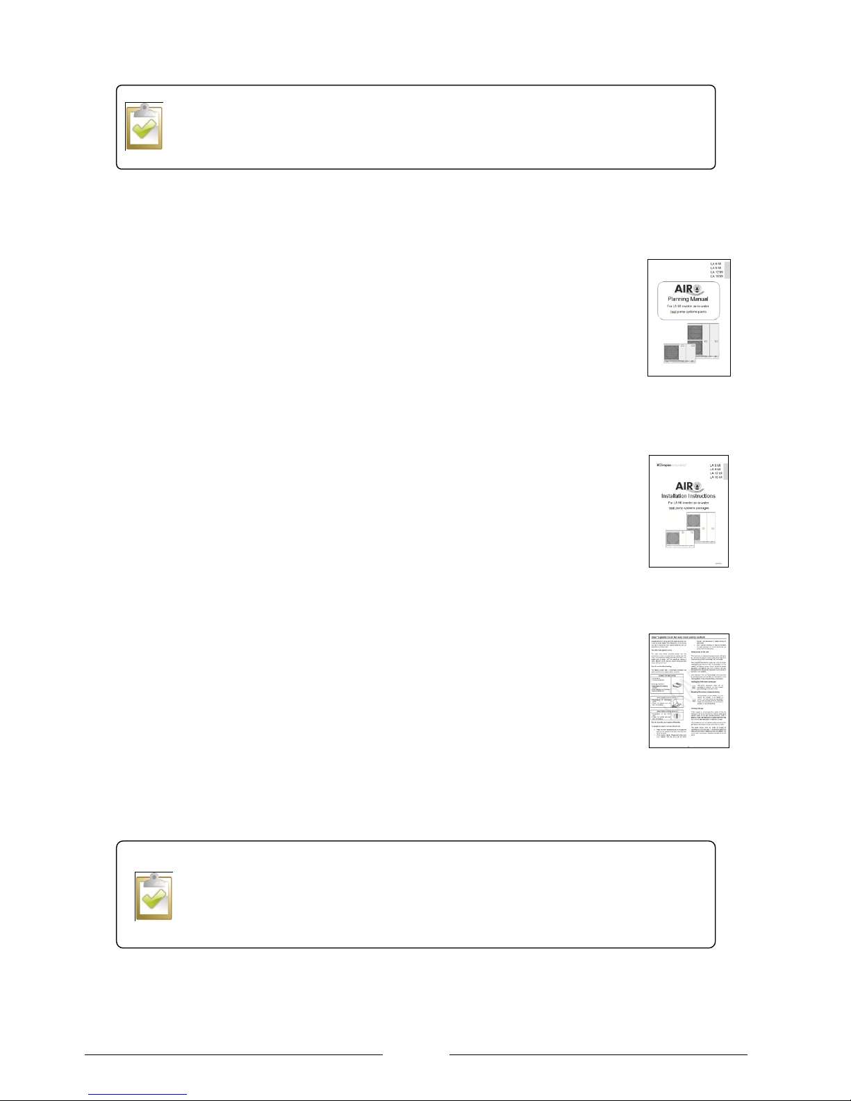
The following documents are available to aid in the planning, installation, operation and maintenance of the Air-eau heat
pumps:
Technical manuals
Contains the necessary information required during the planning stages.
Air-eau inverter heat pumps packages
SmartRad
Installation instructions
Contains the necessary information required during the installation.
Air-eau inverter heat pump packages (this document)
EC-eau cylinders
SmartRad
User guides
Contains the necessary information for the user for operation and maintenance of the system
Air-eau heat pumps (Pack 1 and 2 – standard heating and DHW) for standard users
Air-eau heat pumps (Pack 1 and 2 – standard heating and DHW) for sheltered housing
The installation of an Air-eau heat pump should only be carried out by a suitably trained and
competent person who is approved by Dimplex. All installations should be in accordance
with this document and the planning manual to ensure efficient operation.
The installation instructions are intended for use by the installer whilst they are on site.
Further clarification can be obtained from the relevant technical manuals.
Page 3

Page 3
Contents
Supporting documents ......................................................................................................................................................... 2
Section 1: Scope of delivery and handling ................................................................................................................................ 5
Table 1: Items supplied with the LA MI ................................................................................................................................. 5
Product handling .................................................................................................................................................................. 5
Section 2: Pre-installation checks ............................................................................................................................................. 6
Intended Use ........................................................................................................................................................................ 6
Section 3: Installation considerations ........................................................................................................................................ 7
Installation location ............................................................................................................................................................... 7
Fixing of the heat pump ........................................................................................................................................................ 7
Minimum Ventilation clearances ........................................................................................................................................... 8
Minimum maintenance clearances ....................................................................................................................................... 8
Wall mounting ....................................................................................................................................................................... 8
Section 4: Heating System Connection .................................................................................................................................... 9
External pipe work ................................................................................................................................................................ 9
Minimum heating water flow rate .......................................................................................................................................... 9
Taconova flow checker ......................................................................................................................................................... 9
Frost protection .................................................................................................................................................................. 10
Condensate ........................................................................................................................................................................ 10
Flushing the system ........................................................................................................................................................... 10
Filter ................................................................................................................................................................................... 10
Filling the system ................................................................................................................................................................ 11
De-aeration ......................................................................................................................................................................... 11
Expansion vessel sizing ..................................................................................................................................................... 11
2 port valves ....................................................................................................................................................................... 11
Controlling DHW temperature ............................................................................................................................................ 12
Section 5: Electrical Connection ............................................................................................................................................. 13
Routing of cables within the heat pump .............................................................................................................................. 13
Ducting cables .................................................................................................................................................................... 13
Connection of the power supply to the Heat pump ............................................................................................................. 14
Main power supply cable .................................................................................................................................................... 14
Inline flow boiler .................................................................................................................................................................. 16
Domestic hot water immersion ........................................................................................................................................... 16
Controller cable .................................................................................................................................................................. 17
Electrical connections with the system ............................................................................................................................... 17
Section 6: Installation of the controller .................................................................................................................................... 19
Mounting the controller ....................................................................................................................................................... 19
Section 7: Programming of the controller ................................................................................................................................ 20
Timer/Clock Setting Display ............................................................................................................................................... 21
Operation Mode Button ...................................................................................................................................................... 21
Inline flow boiler ( Enable / Disable ) .................................................................................................................................. 21
System Check Button ......................................................................................................................................................... 21
Page 4

Page 4
Setting the Advanced settings ............................................................................................................................................ 22
Setting the Advanced settings (continued) ......................................................................................................................... 23
Setting the Advanced settings ............................................................................................................................................ 24
Weekly timer setting ........................................................................................................................................................... 25
Enable / Disable timer ........................................................................................................................................................ 25
Setting the timer ................................................................................................................................................................. 25
Section 8: Setting the system to work ..................................................................................................................................... 26
Hydraulic circuit .................................................................................................................................................................. 26
Heat pump .......................................................................................................................................................................... 26
Section 9: Technical specification of the LA MI range ............................................................................................................ 27
Performance Data .............................................................................................................................................................. 28
Performance Data .............................................................................................................................................................. 29
Product Dimensions LA 6 MI and LA 9 MI .......................................................................................................................... 30
Product Dimensions LA 12 MI and LA 16 MI ...................................................................................................................... 31
Section 10: Annual System Health checks ............................................................................................................................. 32
Heat pump .......................................................................................................................................................................... 32
Electrical ............................................................................................................................................................................. 32
Hydraulic ............................................................................................................................................................................ 32
Cylinder .............................................................................................................................................................................. 32
Wall mounted thermostat.................................................................................................................................................... 32
Heat pump controller .......................................................................................................................................................... 32
Section 11: Trouble shooting for the installer .......................................................................................................................... 33
Section 12: Error codes .......................................................................................................................................................... 34
Section 13: Standard packages .............................................................................................................................................. 37
Package 1 and 2 ................................................................................................................................................................ 37
Suggested additional components ..................................................................................................................................... 38
Package 1 and 2 – Plumbing Schematic ............................................................................................................................ 39
User‟s guide to an Air-eau heat pump system .......................................................................................................................... 1
Page 5
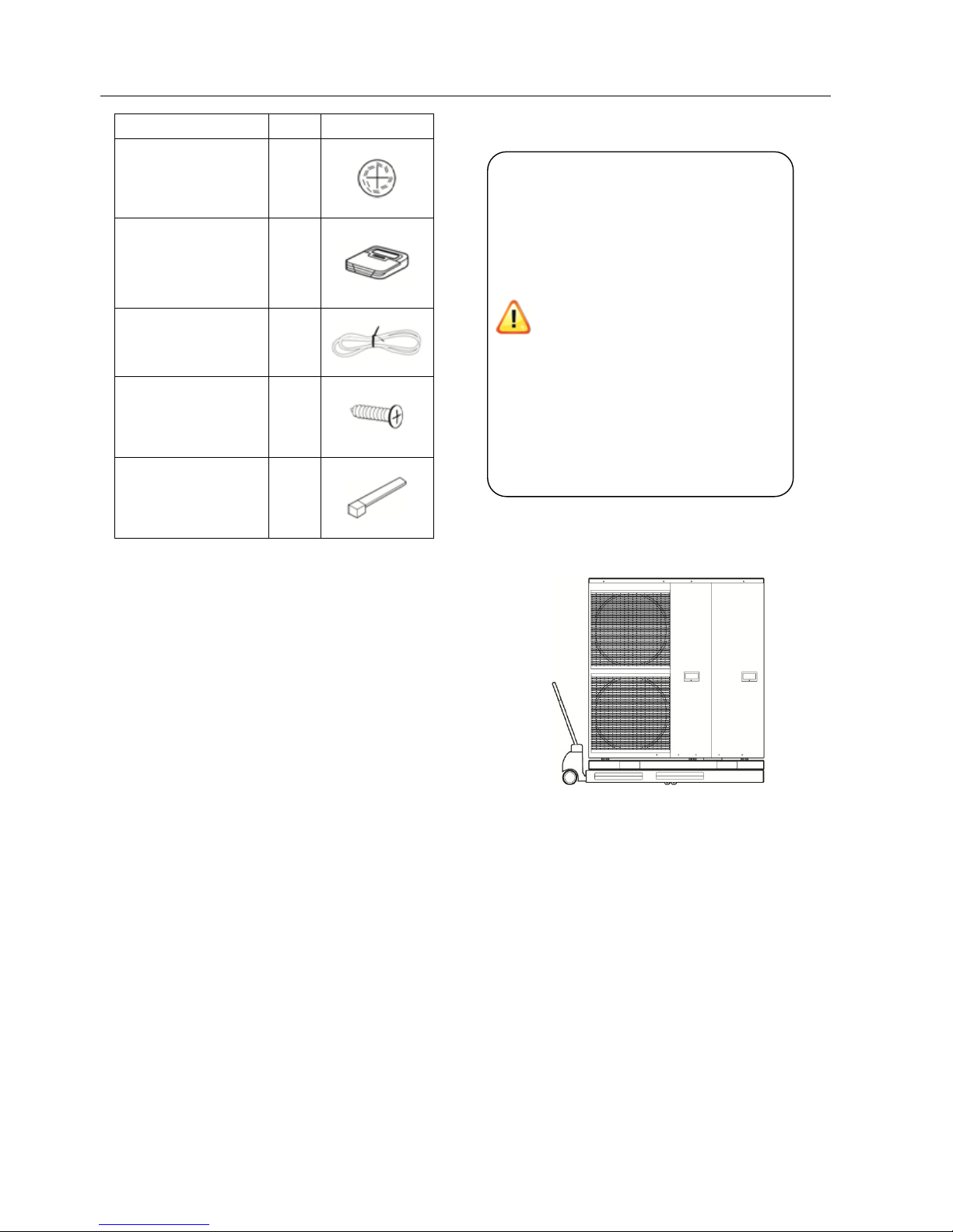
Section 1: Scope of delivery and handling
Description
Qty
Protective grommet to
prevent damage to
cables (LA 12 / 16 MI
only)
2 + 3
Remote controller for
internal wall mounting
1
Remote controller
cable 15m long
1
Screw (M4 self tapping
- 14mm) for wall
attachment of remote
controller
3 Cable ties
3
Table 1: Items supplied with the LA MI
Product handling
Figure 1: Moving a heat pump with a pallet truck or similar
The heat pump is large and heavy. The
handling of the unit should only be done
using lifting tools and sling which can be
fitted into sleeves at the unit‟s base.
Use a wooden pallet for transporting the
heat pump to the final installation
location.
Note that the two metal rails that hold
the heat pump together are essential for
the structural stability and should not be
removed. Removing these rails would
invalidate the warranty.
When transporting the heat pump,
ensure that it is not tilted more than 45°
(in any direction). Tilting the heat pump
would cause the oil from the compressor
to cause damage to other components
within the refrigerant circuit.
Page 6
Page 6
Section 2: Pre-installation checks
Intended Use
This device is only intended for use as specified by
Dimplex as detailed within this technical manual. The airto-water heat pump is to be used exclusively for the
heating of heating water in a closed circuit. Any other use
beyond that intended by the manufacturer is prohibited.
Persons, especially children, who are not capable of
operating the device safely due to their physical, sensory
or mental abilities or due to their inexperience or lack of
knowledge, must not operate this device without
supervision or instruction by the person in charge.
Before starting the practical work the installer must ensure
that the following information has been confirmed during
the design stage.
The heat pump has been correctly sized to meet
the heat load.
The heat emitters system has been suitably sized
ensuring a low flow temperature design.
Any requirements under the MCS scheme (if
applicable) have been met.
The cylinder has been correctly selected to
match the Domestic hot water demand and also
match the heat pump.
The method of communicating a heating demand
to the heat pump as been confirmed i.e. wall
thermostat
Correct selection of the heat pump, heat
emitters and circulation system is essential for
efficient operation of the entire system.
For information about efficient design and
operation see the Inverter heat pump planning
Page 7
Page 7
Section 3: Installation considerations
Installation location
The heat pump is for outdoor installation only. The
following should be verified. Further information is
available in the planning manual.
Planning permission has been applied for where
necessary.
There is adequate clearance for efficient
performance as shown in Figure 3 and the
discharged air does not recirculate.
The unit is positioned to minimise the effects of
noise upon the properties occupants and its
neighbours.
The condensate can easily be drained away.
Hydraulic connections can easily be made to the
heating system and the DHW cylinder.
There is no risk of a flammable gas leak or any
outlets vents from any other system.
The wiring lengths come within reasonable
ranges particularly taking note of the 15m
controller cable.
The heat pump is adequately fixed to prevent
tipping.
Fixing of the heat pump
The heat pump should be fixed on two flat, horizontal and
solid hard surfaces such as concrete pads that are
capable of taking the unit‟s weight and draining the
condensate. The fixing should be strong enough to
prevent the unit from tipping over if the base becomes
unlevel over time.
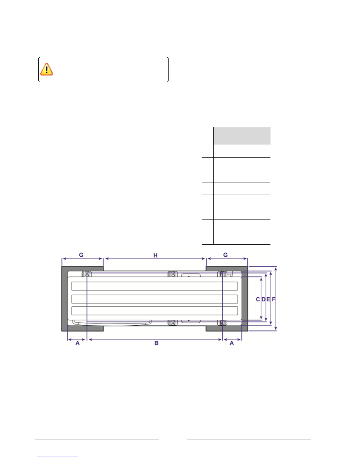
Suggested dimensions
of concrete pads
A
152
B
980
C
300
D
356 E 400
F
520
G
400
H
600
Figure 2: Top view of two concrete mounting blocks that allow the condensate to drain away via a gravel soak away.
The installation of an air source heat pump
should be carried out by a Dimplex Accredited
installer.
Page 8
Page 8
Minimum Ventilation clearances
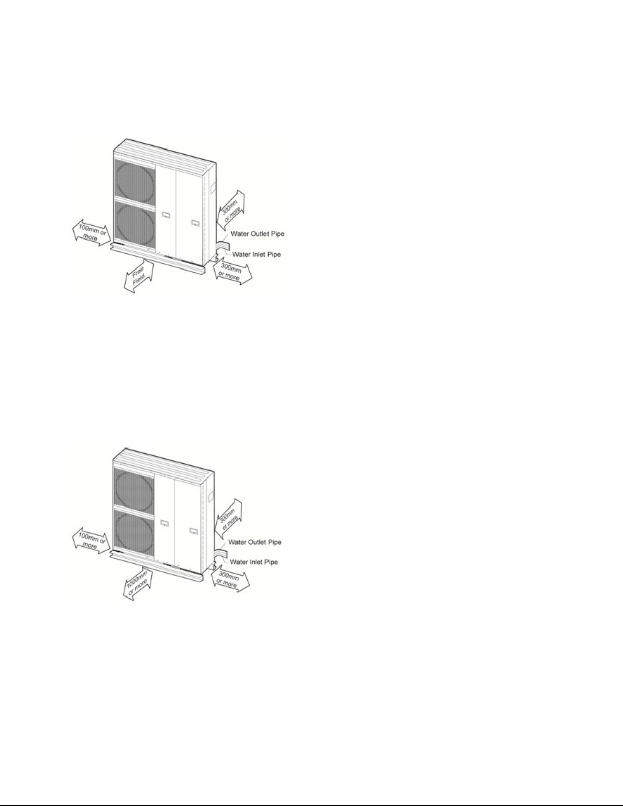
For adequate air flow the distances shown in Figure 3
must be observed. The free field indicates that no object
will disrupt the air flow out of the unit.
Figure 3: Minimum distances to objects to ensure adequate
ventilation
Minimum maintenance clearances
It must be possible to carry out maintenance work without
hindrance. The clearances displayed Figure 4 should be
observed. For example if the unit is installed on a balcony
there must be a space measuring 1000mm in front of the
unit of maintenance.
Figure 4: Minimum clearances for maintenance (not
including clearance for air circulation)
Wall mounting
If the heat pump is to be wall mounted a condensate
collection tray (supplied by the installer) should be fixed
under the heat pump. The pipe from the tray to a suitable
drain should be heated so that it can‟t freeze and become
blocked.
Page 9
Page 9
Section 4: Heating System Connection
The following should be verified before connecting to the
heating system. Further information is available in the
planning manual.
The 50L minimum water volume of the system is
observed by the installation of a buffer tank.
A dirt filter is installer on the return pipe to the
heat pump.
The pipe sizes are adequate to allow the correct
minimum water flow rate through the heat pump.
A by-pass valve has been designed into the
circuit to ensure there is always flow though the
heat pump even when the heating circuits are
closed.
Air bleed valves have been installed at every
highpoint in the pipe work.
External pipe work
The pipe work running from the heat pump into the
property should be sufficiently insulated to minimise the
heat loss and consideration should be given to using the
correct material so that it does not corrode.
Minimum heating water flow rate
The minimum water flow rate which is stated in the
„performance data table‟ must be observed. The
following factors should be considered:
Hydraulic resistance of the pipe work. Special
attention should to given to ensure the correct
pipe diameter is chosen considering the
required flow rates.
As a rule of thumb 28mm pipe work should be
used although the sizing of the pipe work
remains the responsibility of the installer.
To minimise energy consumption the pump
should run of the lowest speed possible whilst
still achieving the correct flow rate. The
resistance of all the pipe fittings, filter, heat
emitters and condenser must be taken into
account.
Failure to observe the minimum water throughput will
cause the heat pump not to work due to operation of the
flow switch alarm (H62).
The maximum water throughput is 20% more than the
stated minimum water throughput. Exceeding the
maximum flow rate would result in an inefficient system
operation due to increased pumping losses.
For systems in which the heating water flow can be shut
off via actuators or thermostatic valves an overflow
bypass valve must be installed to guaranteed to minimum
water flow rate.
Taconova flow checker
The Taconova flow checker is provided in every system
package to provide a simple way to verifying that the flow
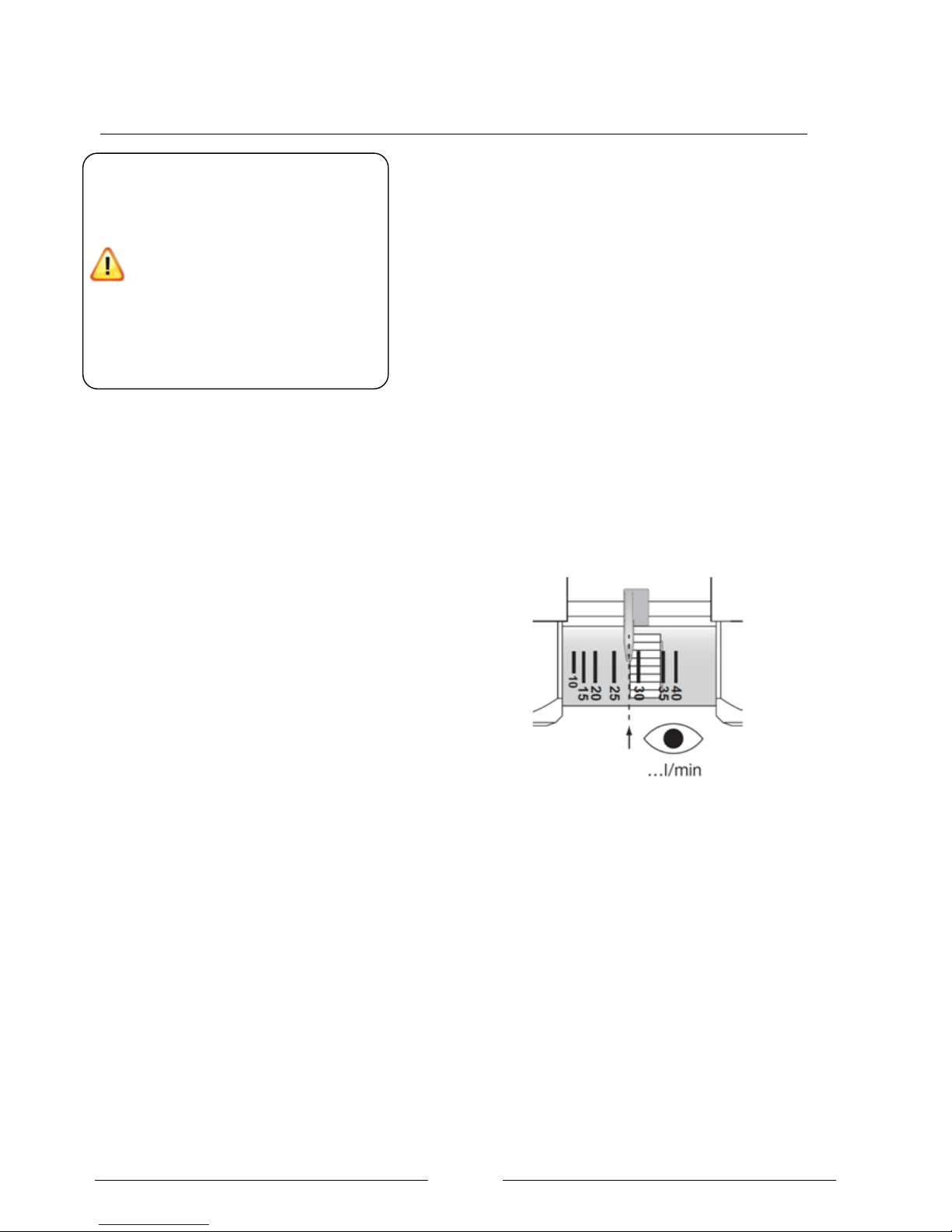
rate is correct. The flow rate is read on the bottom of the
spinner as shown in
Figure 5: Correct reading of flow rate on the taconova flow
checker
The flow checker should be installed in a visible location
inside the property and as close to the heat pump flow as
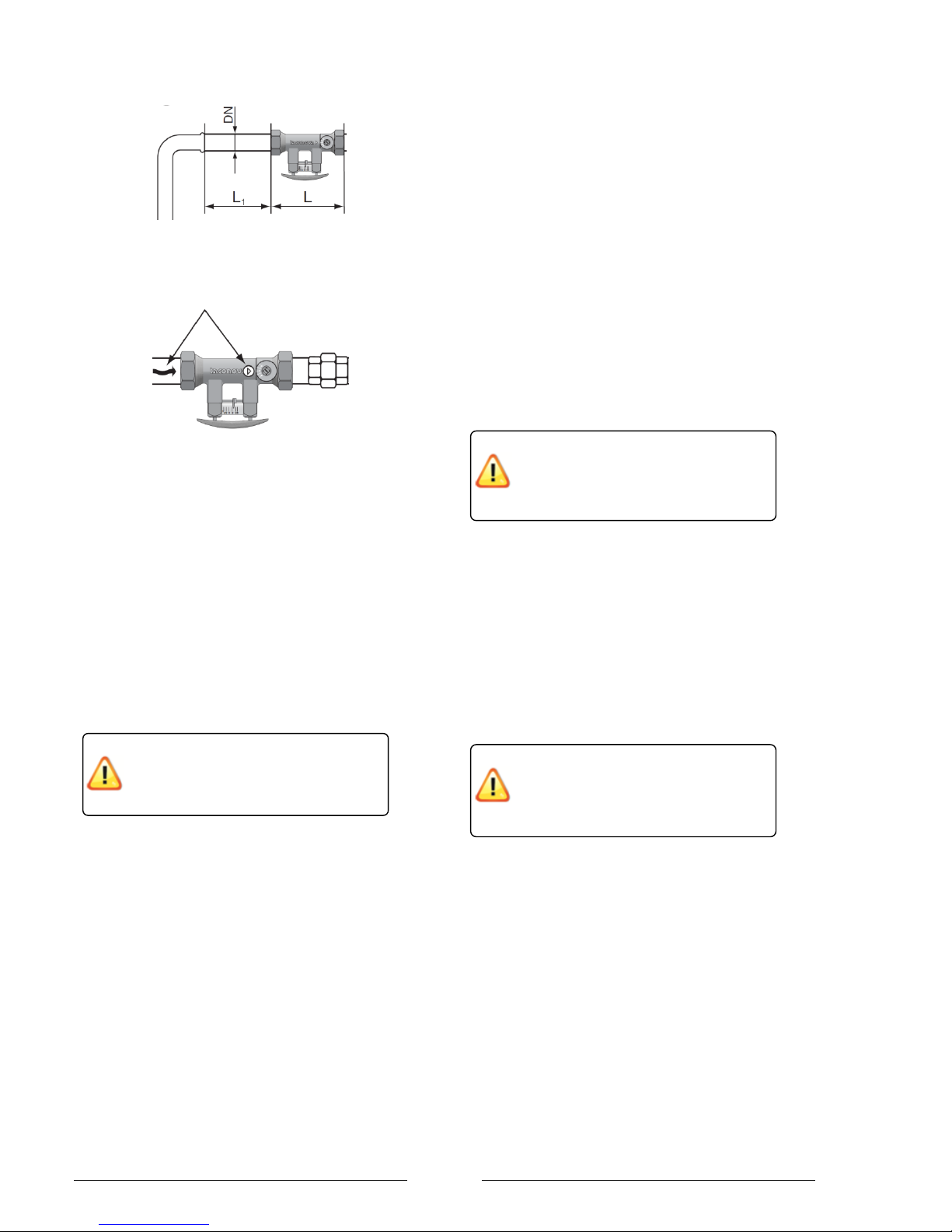
possible. In order given an accurate reading the pipe
installation distances shown in Figure 6 should be
observed as well as the flow direction as shown in Figure
7.
It is important to install the flow checker on the flow pipe
so it is protected from impurities within in the system via
the filter on the heat pump return.
When connecting the heating system,
all applicable regulations must also be
adhered to including all relevant
European and national regulations and
local building regulation codes.
Work that requires the covers to be
removed must only be carried out under
supervision of qualified contractor,
installation engineer or service person.
The installation of an air source heat
pump must be carried out by a Dimplex
Qualified installer.
Page 10
Page 10
Figure 6: Minimum straight pipe distance before entrace to
Taconova unit
Figure 7: Ensure the flow rate through the Taconova is in
the same direction as the arrow
Frost protection
So long as the heat pump is connected to the mains
electrical supply the automatic antifreeze function will
prevent the water in the pipes freezing during cold
weather.
In case of a prolonged power supply failure or a
circulation pump failure the system must be drained using
the screws on the flow and return connections. When
water is idle inside the system, freezing up is very likely
to happen which could damage the system beyond
economic repair.
The installer should conduct a risk assessment to
determine the likelihood of water freezing in the heat
pump and interconnecting pipe work in the event of a
power failure during cold weather. The heating circuit
should be dosed with suitable antifreeze if heat pump
system is in a building where a power failure cannot be
detected or the occupants would be unable to drain the
system. If antifreeze is used the concentration should be
large enough to prevent freezing for the coldest local
temperature and the installer should ensure the glycol is
vented to a suitable place to prevent contamination of the
environment or sewage system in the event the pressure
relief valve activating.
Condensate
During normal operation the heat pump will remove water
vapour from the air. The condensate will run down the
evaporator into the condensate tray where it will drain out
of the unit. Defrosting takes place up to 16 times per day,
with up to 3 litres of condensed water being produced
each time.
Condensed water that forms during operation must be
drained off frost-free. The heat pump must be mounted
on a level surface to guarantee proper drainage. The
condensate should drain onto a surface such as gravel.
If the condensate is drained into a pipe, it must have a
minimum diameter of 50mm and should be fed into the
drain for rain water to ensure that large quantities of
water can be drained off.
Flushing the system
It is advisable to fit specific connections for flushing and
filling as shown in the plumbing schematics. Before
connecting the heating water system to the heat pump,
the heating system must be flushed to remove any
impurities and residue from sealants, etc. Any
accumulation of deposits in the condenser could reduce
the heat pumps performance. Do not use worn out piping
that may have become blocked over time.
Filter
It is essential to install a filter immediately before the
water inlet to the heat pump. Not installing this filter would
invalidate the warranty of the heat pump as debris can
easily block the condenser channels.
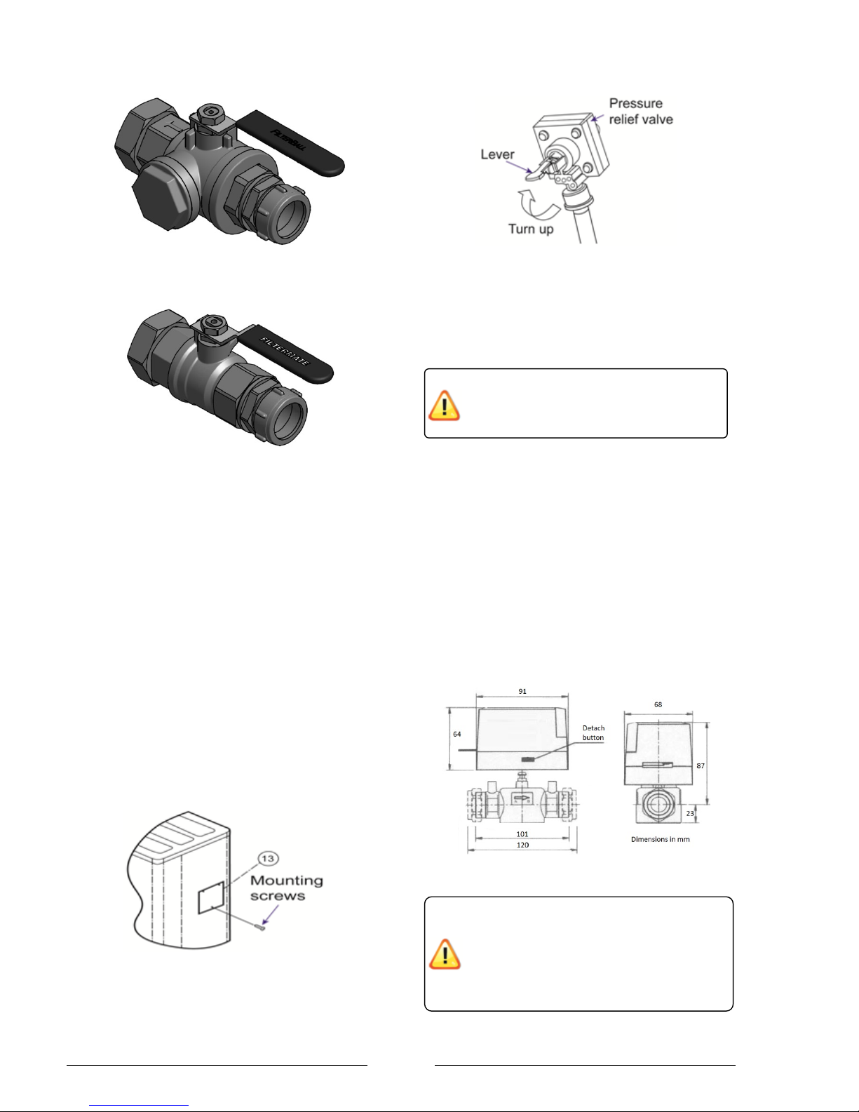
The MFK114 isolation valve as shown in Figure 8 is
included in the heat pump packages. The valve can be
closed and the filter removed and checked without having
to drain the system.
Ensure that impurities are not flushed
though the heat pump since they could
block the channels in the condenser.
The condensate must drain on to an
surface that is freely draining. It must
not drain on to footpaths or patios as it
could refreeze and become a hazard.
If the heat pump is taken out of service
or in the event of a power failure, the
system has to be drained if freezing
weather is a possibility.
Page 11
Page 11
Figure 8: Isolation valve and filter supplied in LA MI
packages to be fitted to the heat pump return.
Figure 9: Isolation valve supplied in package to be fitted to
the heat pump flow.
Filling the system
The system should be filled with potable water. The
system water should be treated with standard central
heating inhibitors.
The cold fill gauge pressure on the heat pump should be
between 0.8 and 1.5 bar (0.08-0.15MPa). This will rise
during normal operation.
De-aeration
Air trapped in the system causes air locks which in turn
cause poor water flow around the system. Every high
point in the system should have a means of bleeding out
air which is supplied by the installer.
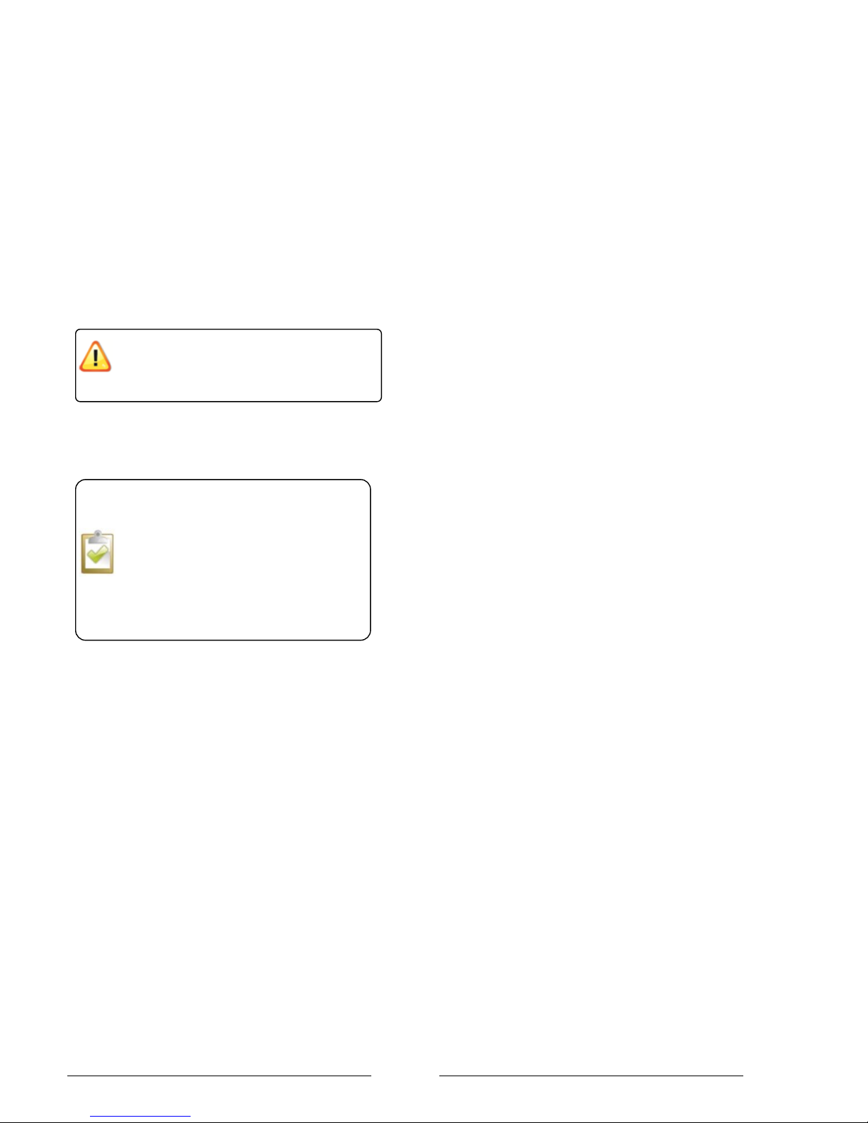
The pressure relief valve shown in Figure 11 can be used
to purge the air from the heat pump during filling.
Figure 10: Location of pressure relief valve
Figure 11: Pressure relief valve
Expansion vessel sizing
The heat pump comes with an expansion vessel already
installed as shown in the „Performance data table‟.
For most installations the 10L expansion vessel should
be able suitable with a volume up to 150L and a static
height of 7m. The 6L expansion vessel should be suitable
for a system volume up to 90L and a static height of 7m.
2 port valves
The heat pump packages include 2 x F228 Horstmann
two port valves as shown in Figure 12 to switch between
space heating and domestic hot water mode. Fit the
valves ensuring that the actuator head is not below the
horizontal level of the pipe work and that the flow is in the
direction of the arrow. Remember to make allowances for
maintenance and replacement.
Figure 12: Dimensions of F228 valve
The F228 valves have been specifically
selected for their fast operating times. W hen
switching from heating to DHW the heat
pump flow must not be restricted. If a
different valve is used, the valve must be
fully open within 6 seconds of being
switched.
Depending upon the specific system the
installer must determine if a second
expansion vessel is required.
Page 12
Page 12
Controlling DHW temperature
The cylinder temperature is controlled via an NTC2
sensor.
For safety reasons the heat pump controller also checks
for continuity from the DHW thermostat. The temperature
regulation thermostat and high limit stat are wired in
series. To keep the contacts closed on the regulation stat
the dial must be set to maximum. The contacts on the
high limit stat will remain closed during normal operation.
If the heat pump does not detect continuity across both
the regulation stat and high limit stat an H91 error will
occur.
A label similar to that shown in Figure 13 should be
supplied by the installer and fixed on the cylinder to let
the user know.
Figure 13: Notice to be supplied by the installer and fixed
next to cylinder thermostat
TEMPERTURE ADJUSTMENT
The temperature of the hot water in this
cylinder is set using the wall mounted heat
pump controller. The setting shown on this
thermostat does not affect the hot water
temperature.
For normal operation the dial should be
set to the maximum position.
The thermostat on the cylinder should
not be modified to disable the regulation
stat or high limit stat.
Page 13
Page 13
Section 5: Electrical Connection
Routing of cables within the heat pump
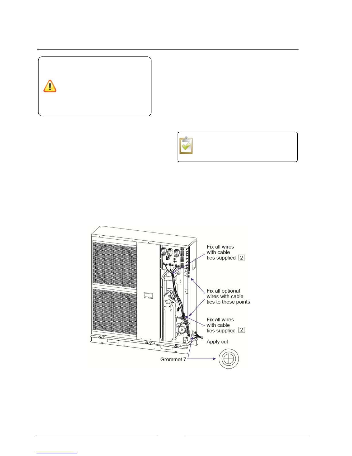
To avoid electrical cables becoming damaged
by sharp edges they must exit through the
grommets located on the bottom edge of the
machine.
The cables must be secured using the
supplied cable ties and the clamps on the
control board.
Ducting cables
To access the electrical connections only the front right
hand panel of the heat pump outer casing needs to be
removed as shown in Figure 14.
Depending upon the installation the heat pump could
have the following cables that it will be necessary to
route from the heat pump into the property.
1. Main power supply cable
2. Heat pump controller
3. Communication cable for 2 way valves, high
limit stat etc, room thermostat.
4. Domestic hot water sensor
5. Domestic hot water immersion heater (booster
heater)
Ducting should be used to ensure that the enclosed
cables are protected from the effects of weather,
mechanical snagging or wear, rodent damage ect. The
ducting should be positioned in such away to ensure
that water will not track along the ducting and into the
heat pump or property.
Figure 14: Correct cable routes through heat pump
For typical wiring and hydraulic
schematics see section 16 at the end of
this document.
When connecting the heat pump to
the power supply, the relevant EN
standards must be complied with.
Any further connection requirements
stipulated by local utility companies
must also be observed. It is important
that the hydraulic connections have
been completed prior to switching on
the power supply.
Page 14
Page 14
Connection of the power supply to the Heat pump
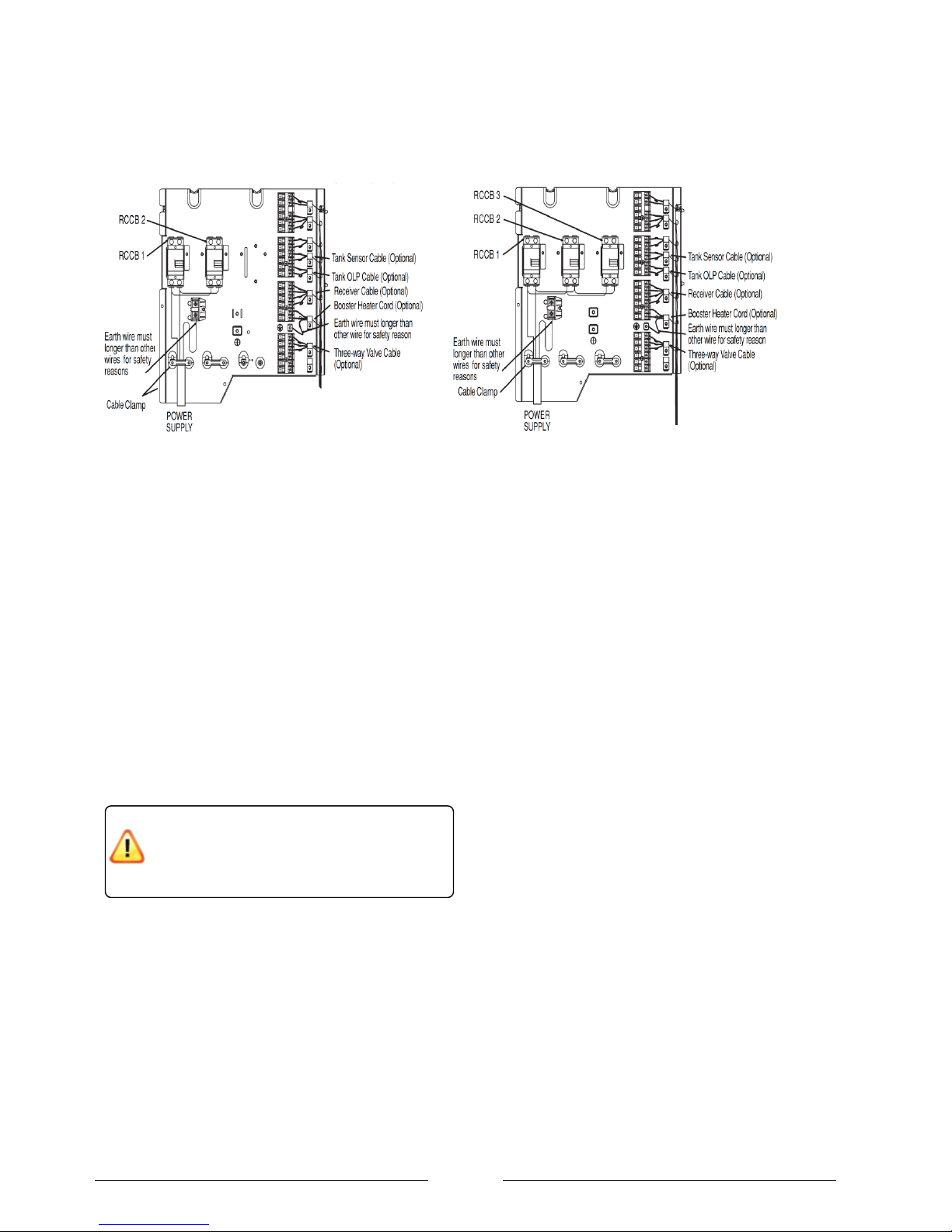
LA 6 and 9 MI LA 12 and 16 MI
Figure 15: Connection of the power supply cable
Main power supply cable
The power connection of the heat pump is made via a
standard 3-core cable. The cable has to be supplied by the
installer and the wire cross-section is to be selected
according to the power consumption of the heat pump as
shown in
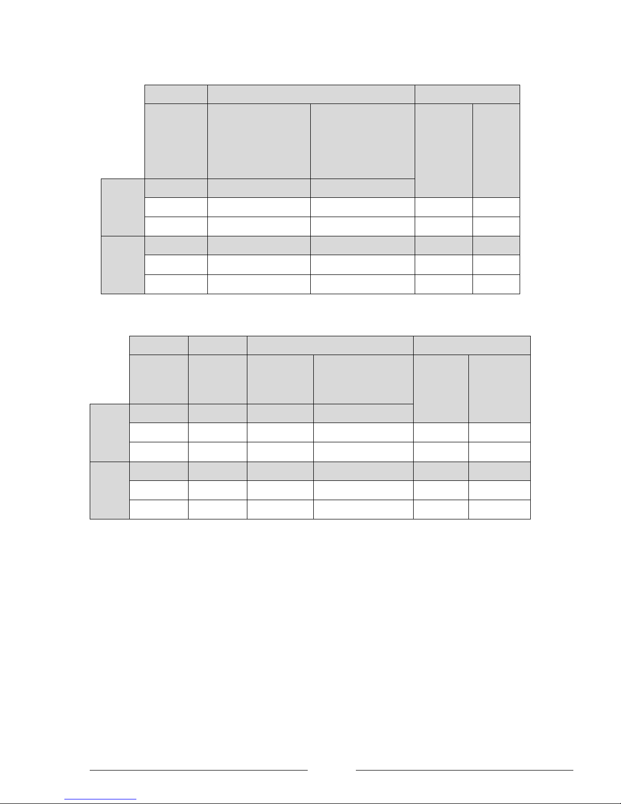
Similarly, the main circuit breaker (MCB) at the distribution
board should be correctly rated as shown in Table 2.
For maintenance purposes the power supply of the heat
pump must be equipped with an isolating device in the
vicinity of the heat pump. The isolating device must have a
contact gap of at least 3mm. In addition to the maintenance
isolator an automatic 2-pole automatic circuit breaker
should be installed.
The maximum current carried in the supply cable
must be calculated using Table 2 depending upon
the how the heat pump is configured. For example,
it is not always necessary to connect the inline flow
boiler. In other installations where there is no DHW
cylinder is not necessary to connection the DHW
immersion. Every installation will require power to
RCCD 1 (compressor and control circuits).
Once the maximum supply current is known the
installer must then supply a suitably rated cable
depending upon the run length and the type of
environment where it will pass.
The heat pump should only be
connected to a permanent mains supply.
Page 15
Page 15
RCCD 1
RCCD 2
MCB
Compressor &
controller
In line flow boiler
+
DHW immersion switched
by heat pump
In line flow boiler
+
DHW immersion switched
by a relay controlled by the
heat pump or no DHW
immersion installed
Total running
current
(Amps)
Suggested
„type C‟
MCB
rating
LA 6 MI
21A
26A
13A
47
50
34
50
LA 9 MI
23A
26A
13A
49
50
36
50
RCCD 1
RCCD 2
RCCD 3
MCB
Compressor
& controller
In line flow
boiler
DHW immersion
switched by
heat pump
DHW immersion switched
by a relay controlled by
the heat pump or no DHW
immersion installed
Total running
current
(Amps)
Suggested
„type C‟ MCB
rating
LA 12
MI
25A
26A
13A
0A
51
63
64
80
LA 16
MI
27A
26A
13A
53
63
66
80
Table 2: Calculation of running current for entire heat pump to size power supply cable and MCB at distribution board.
Page 16
Page 16
Inline flow boiler
Figure 16: Manual reset on the over Inline flow boiler
The OLP located on the inline flow boiler, as shown in
Figure 16 prevents the water from overheating. Before
manually resetting the cause of tripping should be
rectified. The OLP can be manually reset by:
1. Removing the OLP Cover.
2. Using an insulated tool to gently push the centre
button on the OLP.
3. Replace the OLP cover.
Domestic hot water immersion
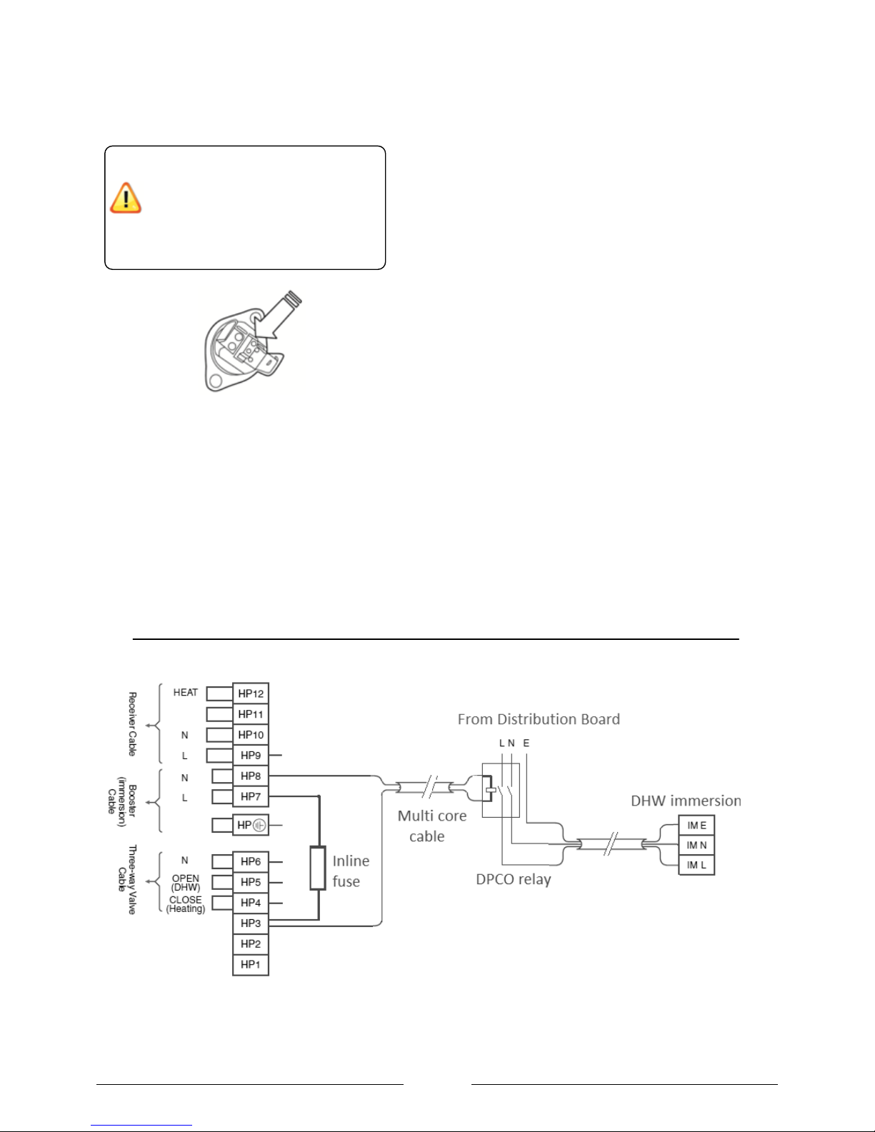
The heat pump is capable of switching a 3kW
immersion directly without the need for an additional
relay as shown on the standard wiring diagram.
Depending upon the wiring runs it may be more
suitable that the heat pump switches a relay rather
than the immersion directly as shown in Figure 17.
This would mean that the cable from the heat pump to
the cylinder could have a lower current rating and
therefore, could be combined with the multi-core cable
rather than run a separate cable.
This method is particularly useful in retro-fit
applications where the existing cylinder already had an
immersion heater and high current supply fitted.
If this is the case the installer should supply an inline
fuse rated at an appropriate current for the relay
selected and the maximum current rating of the multicore cable as shown in Figure 17.
Figure 17: Wiring for Heat pump to control DPCO relay to switch supply for immersion
If the inline flow boiler is not wired in the
frost protection function will not fully
function. The circulation pump will run
but no additional heat will be added to
the system by the inline flow boiler. This
increases the risk of the water in the
system freezing.
Page 17
Page 17
Controller cable
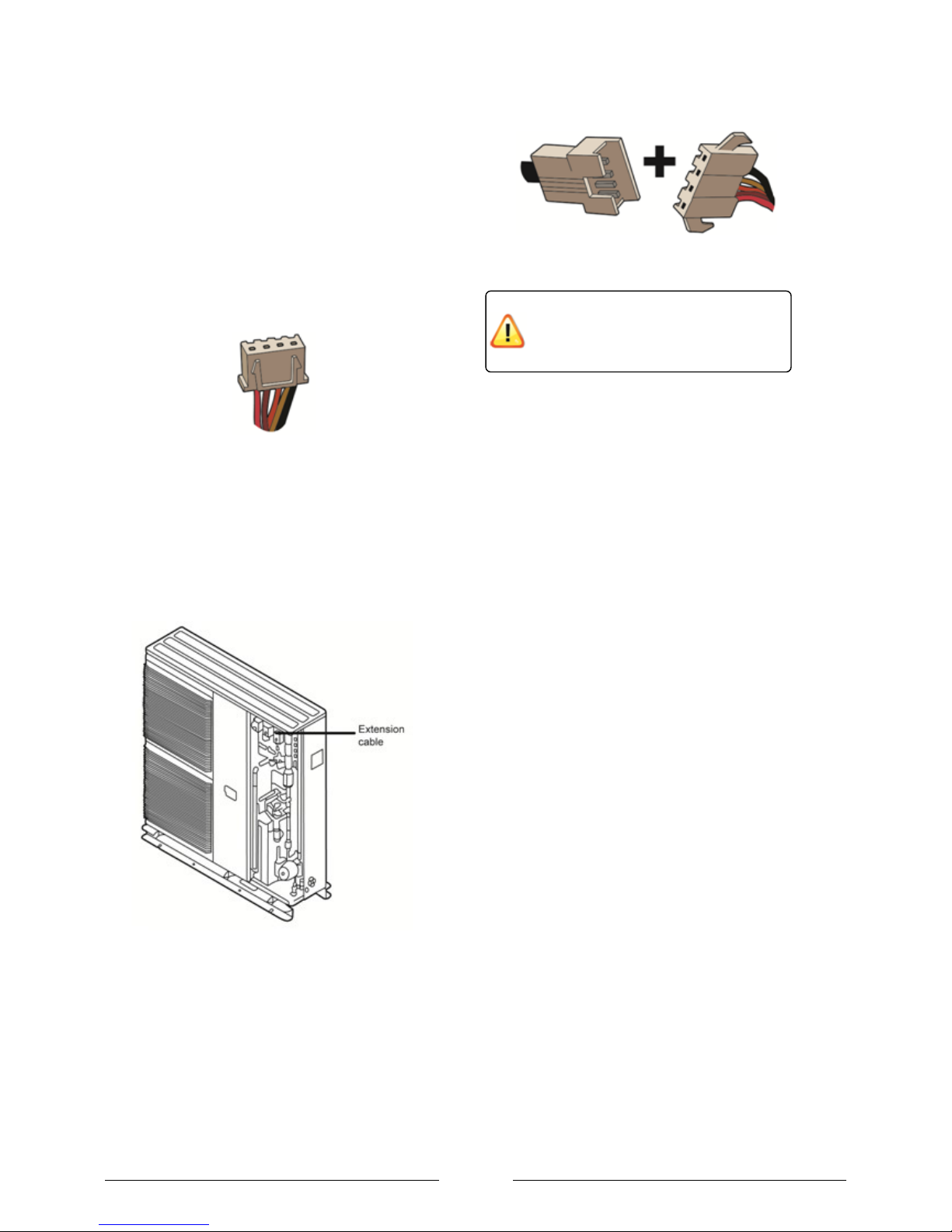
The controller cable is connected to the heat pump
controller using the two rectangular plug connectors as
shown in Figure 18. The cable cannot be extended
because this would increase the resistance and
correct operation of the controller cannot be
guaranteed. The cable is 15m long but 1.5m is
required inside the heat pump leaving 13.5m for
routing to the controller. The cable is included within
the scope of supply. The power for the controller is
supplied from the heat pump.
Figure 18: Connection terminals on the controller cable
to controller inside the property.
The controller cable is connected to the heat pump via
a short extension lead which protrudes from the heat
pump as shown in Figure 19. On the end of the
extension cable is a dust cover that must be removed
before the cable can be connected. The controller
cable connects to the extension cable as shown in
Figure 20.
Figure 19: Location of the extension cable for connection
of the 15m controller cable
Figure 20: Terminals of the extension lead and 15m
controller cable
Electrical connections with the system
The following section contains general information
about the communication connections. Full wiring
diagrams and hydraulics for standard systems are
available in Section 16.
Each end of the controller cable is
different. Make sure you install it the
right way around!
Page 18
Page 18
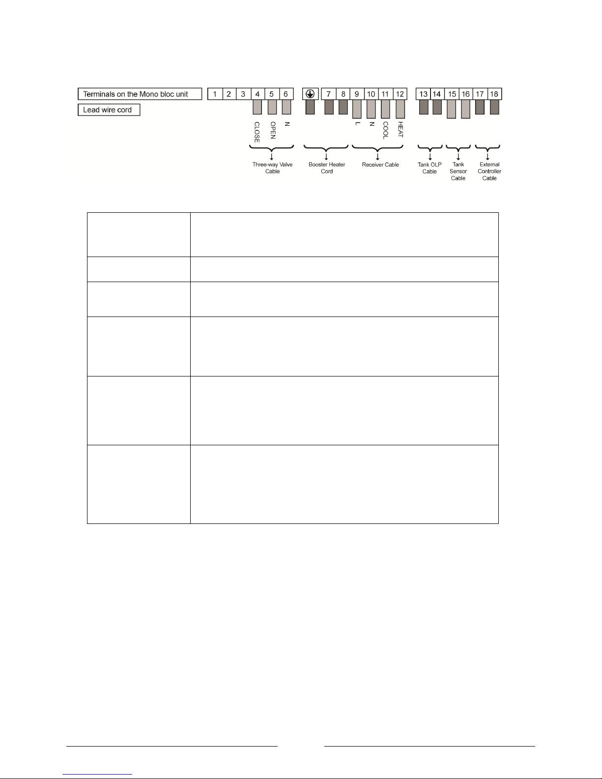
Figure 21: Heat pump communication connections
External controller cable
This can be used to remotely put the heat pump in standby mode upon breaking
the connection from an external control device. When in standby the heat pump
frost protection will still be activated. To enable this function a factory fitted jump
lead between terminals 17 and 18 must be removed.
2 x Two way valves
2 x two-way valves are necessary if the heat pump needs to switch mode from
space heating to domestic hot water production.
Booster (Immersion)
heater
This is the immersion heater installed in the DHW cylinder. It immersion can
either be switched directly by the heat pump or a relay can be fitted locally to the
cylinder as shown in Figure 17.
Receiver Cable
The receiver cable is used to communicate a heating demand to the heat pump
from a device such as a wall mounted thermostat.
Connection of the receiver cable is essential to provide „boiler interlock‟ to
comply with building regulations.
Tank OLP
If the heat pump is doing DHW, the over load protection is connected to the
manually resettable high limit stat on the DHW cylinder. Using this connection is
a way of comply with G3 building regulations.
If such connection is deemed unnecessary a jumper must be connected across
these terminals if the heat pump is programmed for DHW production.
Tank Sensor
The tank sensor is essential for DHW production because it monitors the
temperature in the DHW cylinder. The DHW sensor must be an NTC-2. This
sensor is supplied as part of the standard package.
To comply with wiring regulations it might be necessary for the sensor cable to
be different cable from the other communication cables since it is extra low
voltage and the other cables carrying 240V.
Page 19
Page 19
Section 6: Installation of the controller
The controller should be installed:
In a place which is away from direct sunlight
and high humidity.
On a flat surface to prevent warping of the
remote controller and damage to the LCD
screen.
Where the LCD can be easily seen for
operation. (Standard height from the floor is
1.2 to 1.5 meters.)
In a location where the cable can be fed
though the wall or to the surface of the wall
and attached in such a way as not to cause
snagging.
Mounting the controller
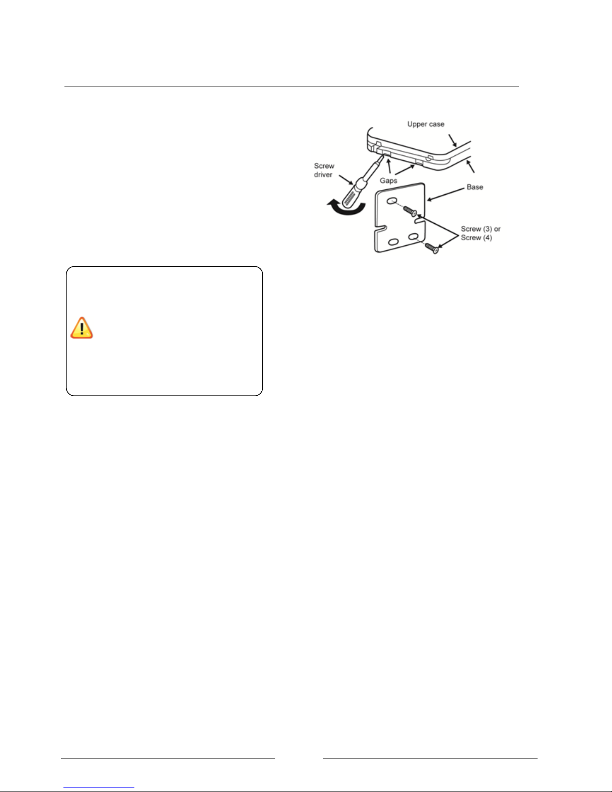
1. Remove the remote controller‟s base by inserting a
flat-tipped screw driver 2 to 3 mm into one of the gaps
at the bottom of the case, and twist to open as shown in
Figure 22.
2. Do not remove the protective tape or paper which is
fixed to the circuit board with-in the upper case.
3. Secure the base to a wall using the screws provided.
Do not over tighten the screws.
4. Connect the controller cable to the upper case and
route it so that it will not be pinched. Clip the upper
case in place on to the base unit on the wall.
Figure 22: Opening the controller case
The controller should be installed in a
location where it is possible for the
home owner to regularly check for
errors. The installer should tell the
customer to check the display
periodically for errors.
In the event of an error involving the
compressor the inline flow boiler will
back up the heat load which will have
higher running costs compared to the
Page 20
Page 20
Section 7: Programming of the controller
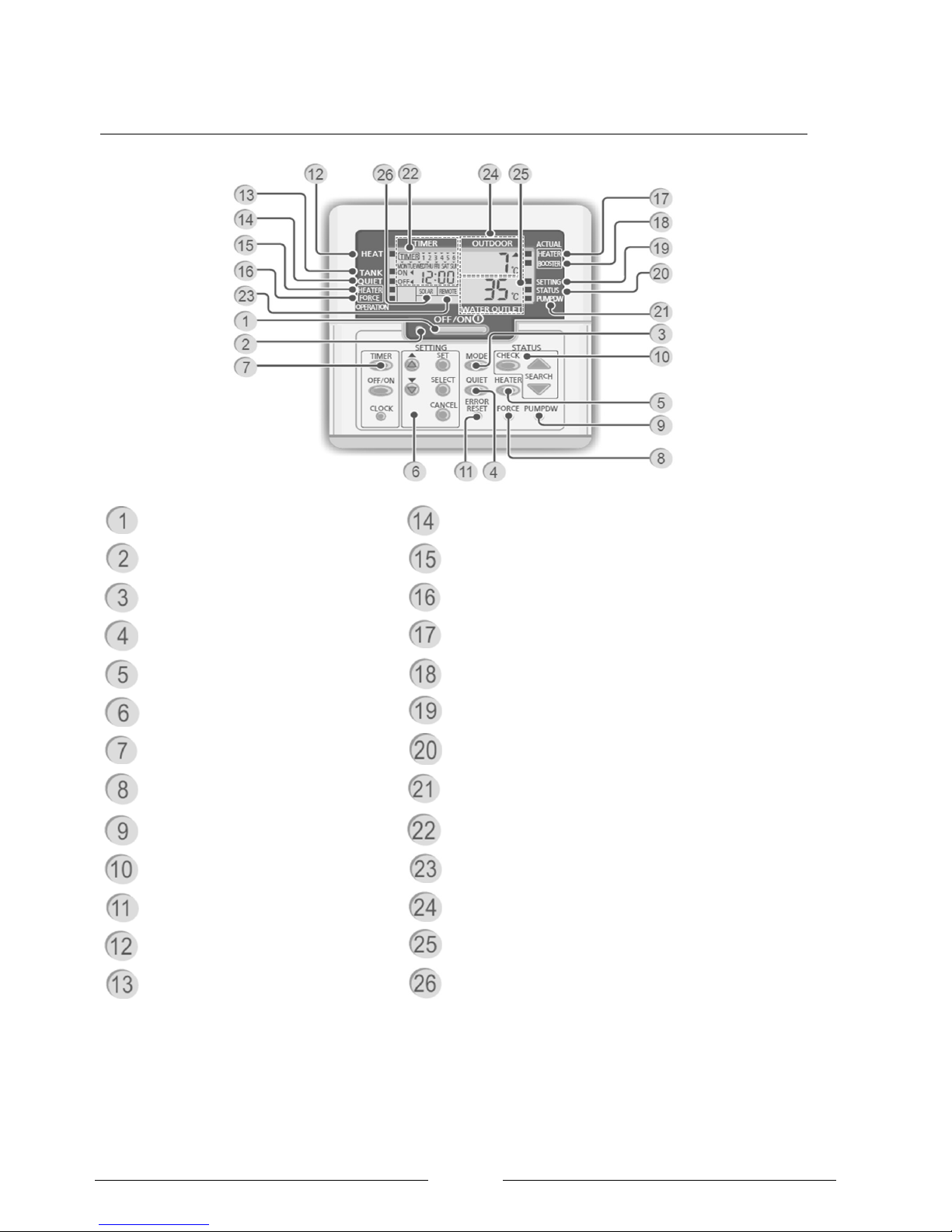
OFF/ON Standby Button
Quiet Operation Indicator OFF/ON
Operation LED
Inline flow boiler request Indicator OFF/ON
Operation Mode Button
Force Inline flow boiler Request Indicator OFF/ON
Quiet Operation Button
Inline flow boiler status (OFF/ON)
Inline flow boiler ( Enable / Disable )
Immersion Heater status (OFF/ON)
System Set-up Buttons
System Set-up mode Indicator OFF/ON
Timer Setting Buttons
System Check mode indicator OFF/ON
Force Inline flow boiler (during error)
System Pump down Mode indicator OFF/ON
System Pump down Button
Timer/Clock Setting Display
System Check Button
Remote Display (not used)
Error Reset Button
Outdoor Ambient Temperature Display
Heating Mode indicator (OFF/ON)
Water Outlet Temperature Display
Tank Mode indicator (OFF/ON)
Solar Display (not used on this model)
Page 21

Page 21
Timer/Clock Setting Display
The time and day must be set at first power on or after
a prolonged power outage. The time must also be set
before the other menus can be accessed.
1. Press .
2. Press or
to set current day.
3. Press
to confirm.
4. Repeat steps 2 and 3 to set the current time.
OFF/ON Standby Button
When the unit is ON, operation LED is lit and the
compressor will operate when required. When in
standby the compressor will not operate however the
circulation pump and inline flow boiler can be activated
to provide frost protection.
Operation Mode Button
Press the mode button to cycle through the following
options. A block will be displayed against the
appropriate text on the controller‟s screen.
1. HEAT ONLY
2. HEAT + TANK
3. TANK ONLY
Quiet Operation Button
Reduces the noise of the heat pump by approximately
5dbA for the double fan heat pumps and 3dBA for the
single fan heat pumps by reducing the fan and
compressor speed. This will affect the COP and kW
output.
Inline flow boiler ( Enable / Disable )
The backup heat provides extra heating capacity via
the inline flow boiler. The boiler will only be able to
activate if this option is selected via this button and the
other conditions set with in the controller are met.
When this option is selected the backup heat indicator
will be displayed.
System Check Button
Press
for 5 seconds to enter this mode. Scroll
through using or
to check:
Water inlet temperature
Tank temperature
Compressor running frequency
Error History
Whilst in the check menu, the last error can be reset
by pressing and holding the „Error reset‟ button.
Page 22
Page 22
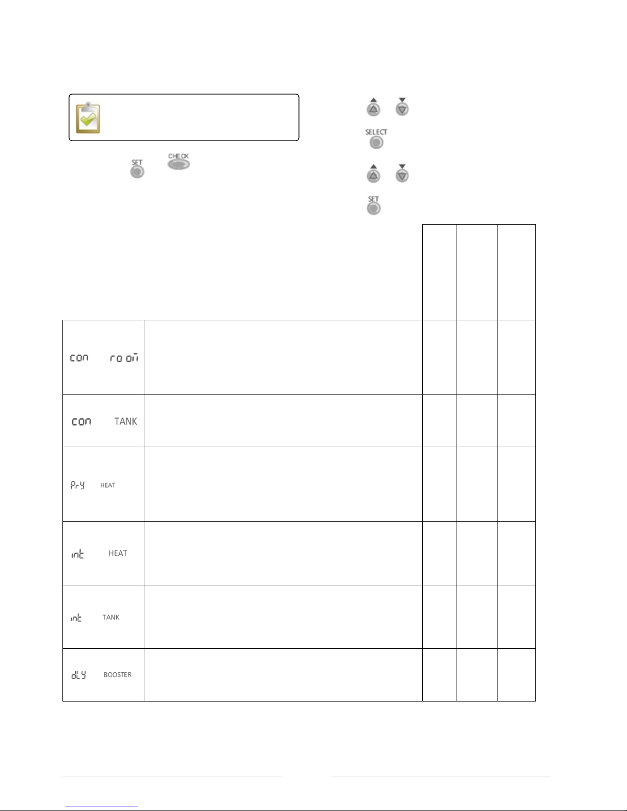
Setting the Advanced settings
1. Press and for 5 seconds to enter the
advanced settings mode. The “SETTING” indicator
will be displayed.
2. Press or
to scroll through the functions.
3. Press
to enter the function.
4. Press or
to select the desired value.
5. Press
to confirm.
Table 3: Suggested Special Functions menu settings.
Default setting
Heating and DHW
(Packs 1 and 2)
Heating only
(Pack 3)
Room thermostat connection (Yes / No)
Yes - the heat pump is interlocked with a wall mounted
thermostat such has the Horstmann PRT1.
No- There is no thermostat proving boiler interlock, the heating
will be regulated on flow temperature.
No
Yes
Yes
Tank connection (Yes / No)
Yes - the heat pump is producing domestic hot water via a
cylinder.
No – there is no DHW installed.
No
Yes
No
Heating Priority (Yes / No)
Yes – The heat pump will only start a DHW request using the
compressor once the space heating is satisfied.
No – The heat pump will operate based upon the parameters
outlined below.
No
No
-
Heating Heat-up interval set
Sets the period of time the heat pump will continue trying to
meet the correct flow temperature before switching across to
DHW production.
This option is only available if PRY HEAT is set to NO.
3:00
0:30
-
Tank Heat-up interval set
Sets the period of time that the heat pump will try and meet the
DHW set temperature before switching across to the heating
demand.
This option is only available if PRY HEAT is set to NO.
0:30
1:00
-
Booster heat delay time set
To set delay timer for cylinder immersion heater to ON if tank
temperature is not reached.
This option is only available if PRY HEAT is set to NO.
1:00
1:30
-
The special functions can only be set if the
Operation LED is OFF.
Page 23
Page 23
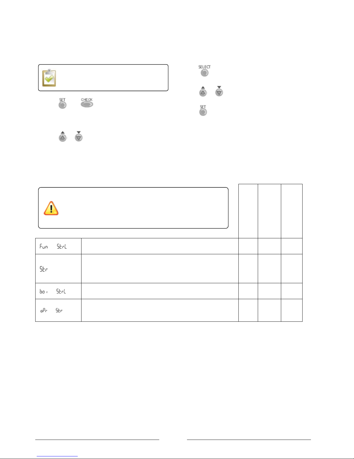
Setting the Advanced settings (continued)
1. Press and for 5 seconds to enter the
advanced settings mode. The “SETTING” indicator will
be displayed.
2. Press or to scroll through the functions.
3. Press to enter the function.
4. Press or to select the desired value.
5. Press to confirm.
Table 4: Suggested Special Functions menu settings.
Default setting
Heating and DHW
(Packs 1 and 2)
Heating only
(Pack 3)
Sterilization (Yes / N0)
To sterilization of the DHW cylinder.
Yes
Yes
-
Sterilisation Day & Time set
To the start time for sterilisation once per week.
Sun
00:0
0
Fri
23:30
-
Sterilisation temperature
To set the temperature for sterilisation function (40C ~ 75C)
70C
60C
-
Sterilisation continue time
To set timer to maintain heating temperature in order to
complete the sterilisation function (5minutes ~ 1 hour)
0:10
1:00
-
The water in the DHW cylinder will be much hotter than usual
during the sterilisation process and this very hot temperature will be
stored in the cylinder until it is drawn off.
Ensure that adequate means of preventing scalding have been
implemented such as Thermostatic valves at the outlets.
The special functions can only be set if the
Operation LED is OFF.
Page 24
Page 24
Setting the Advanced settings
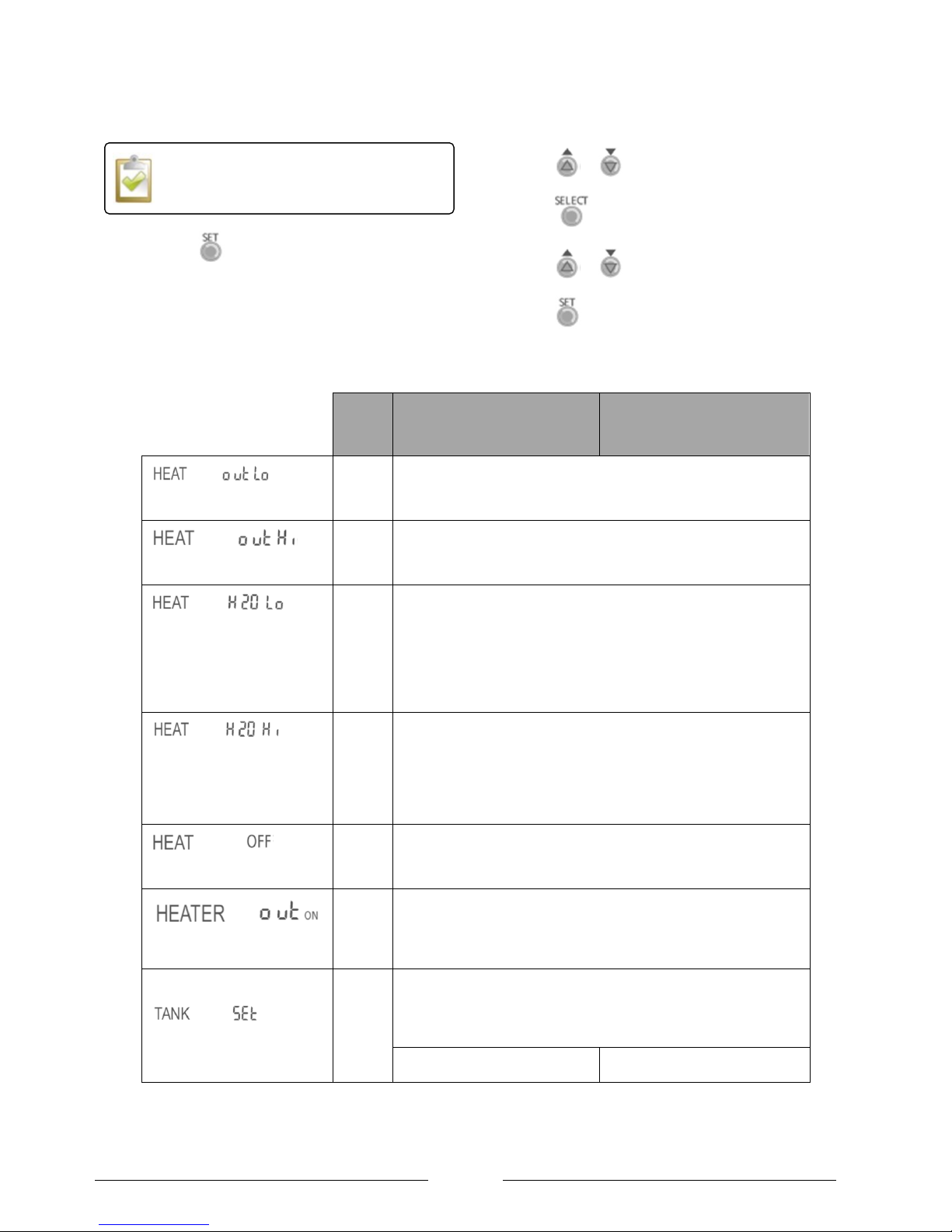
1. Press for 5 seconds to enter the advanced
settings mode. The “SETTING” indicator will be
displayed.
2. Press or
to scroll through the functions.
3. Press
to enter the function.
4. Press or
to select the desired value.
5. Press
to confirm.
Table 5: Advanced operation settings
Default
Pack 1+ 2
Heating and DHW
Pack 3
Heating only
(Range -15C to 15C)
0C
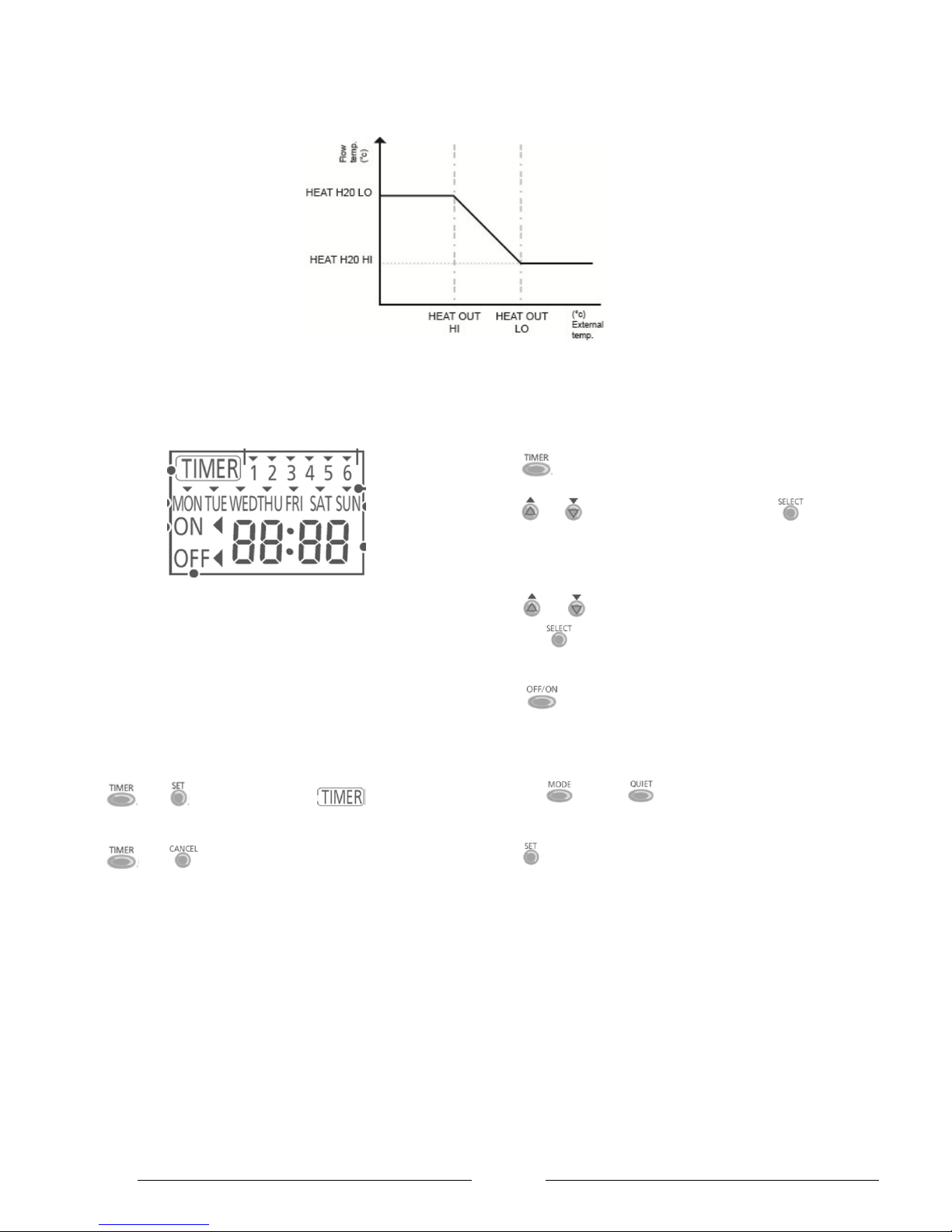
The lower external air temperature on the weather compensation
graph. Typically this is the „design temperature‟ which is determined
during the design process and is normally between -1C to -5C.
(Range -15C to 15C)
15C
The higher external air temperature on the weather compensation
graph. Recommended setting of 15C or the building base
temperature if known.
(Range 25C to 55C)
55C
The water flow temperature corresponding to the lower external air
temperature on the weather compensation graph. The is determined
based upon the choice of heat emitters by the system designer.
Typical values are:
Under floor: 35C
SmartRads: 45C
Radiators: 55C
(Range 25C to 55C)
32C
The flow temperature required for the heat emitters to give the
correct heat output at the minimum design temperature. Typical
values are:
Under floor: 20C
SmartRads: 35C
Radiators: 35C
(Range 5C to 35C)
18C
The external air temperature above which heating is no longer
required so the heat pump operation is blocked. Typical value of
18C.
(Range -15C to 20C)
-3C
The external air temperature below which the inline flow boiler will be
allowed to operate during normal operation. This is dependent upon
the „bivalent temperature‟ as determined during the design process.
Typical values between -1C and -5C.
(Range -40C to 75C)
55C
The temperature of the stored hot water within the domestic hot
water cylinder. Note that if the temperature is higher than the heat
pump can achieve on its own via the compressor the immersion will
automatically heat the cylinder to the required temperature.
45C
N/A
The advanced settings can only be set if the
Operation LED is OFF.
Page 25
Page 25
Figure 23: Weather compensation graph
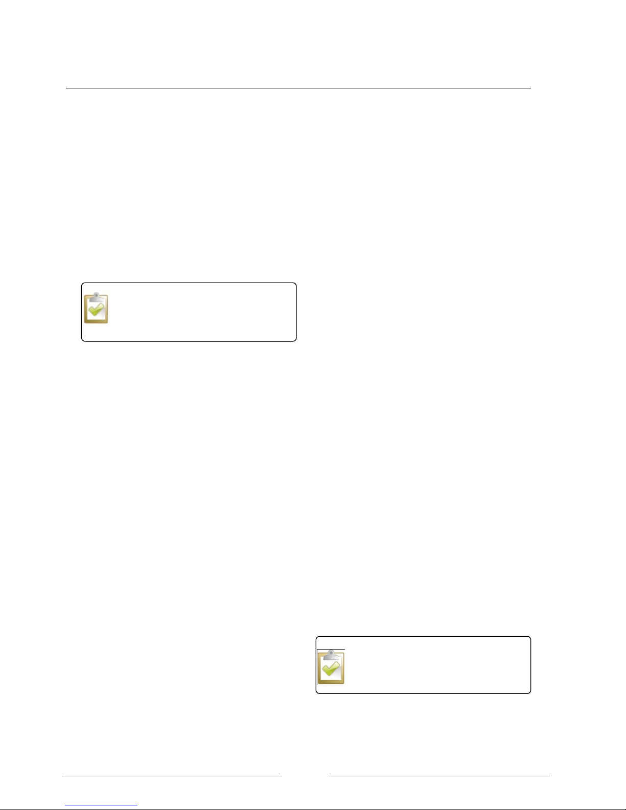
Weekly timer setting
It is possible to set 6 programs per day. This function
can be used to set the time and day in the week when:
The mode changes to HEAT, HEAT + TANK
or TANK.
Quiet mode
Enable / Disable timer
When on the main screen press:
and to activate the timer. will now
be displayed on the main screen.
and to deactivate the timer.
Setting the timer
Press .
Press or to select the correct day. Press
for each of the required days. A hat symbol will be
displayed above the selected days.
The program number 1 to 6 will then start flashing.
Press or to scroll to the correct program and
then press . A hat symbol will be displayed above
the selected days
Press to select if the heat pump should be
turned on or off at the selected time.
Press UP or DOWN to choose the correct time.
Press the and/or to choose what function
will be activated.
Press to confirm the timer setting for the selected
program.
Repeat the above steps to set up the other timer
settings.
.
Page 26
Page 26
Section 8: Setting the system to work
After completing the heating system and electrical
connections the following procedure should be followed
to set the system to work.
Hydraulic circuit
1. After flushing and filling the heating circuit check the
air bleed points to release any air. Top up system if
pressure drops below 0.8 bar.
Once the heat pump starts to operate more air may
be pushed around the circuit so this process will
need to be repeated.
Heat pump
1. Check the operation of pressure relief valve by
using the lever as shown in Figure 11 ensuring that
it re-seats after operation.
2. Check the circulation pump is on speed 3.
3. Ensure that the override levers on the 2 x two port
valves are in the Auto position and the insert guide
is removed.
4. Ensure all of the necessary RCCD‟s are in the ON
position with the red indicator showing and then turn
on the power supply to the heat pump at the
distribution board.
5. Check the operation of the RCCD by using the test
button and return them to the ON position.
6. Set up the controller as described in section 10
using the suggested settings shown in Table 3.
7. Check the controller is not in “Quiet” mode as this
will reduce the heat pumps kW output and increase
heat up times.
8. Place the controller in TANK mode.
9. Activate the heat pump by pressing the OFF / ON
button on the controller.
10. Check the 2 port valve is directing the heating water
into the top of the cylinder coil.
11. Check the water flow rate on the Taconova unit is
within the correct limits. Adjust the circulation pump
if necessary.
12. Check that the heat pump is able to achieve the
correct temperature in the DHW cylinder by reading
the sensor using the heat pump controller.
13. When the DHW demand is fulfilled check the 2 port
valve switches across to heating when deenergised.
14. Switch the controller on to HEAT mode. If the
outdoor temperature is higher than the HEAT OFF
temperature (default 18C) the heat pump will not go
into heating mode. Raise the HEAT OFF
temperature if necessary.
15. Turn the Horstmann wall thermostat into standby
mode. Check that the green light is on the heat
pump controller and verify that the heat pump does
not start.
16. Turn on the Horstmann room thermostat to create a
heating demand.
17. Allow the system to come up to temperature and
check all the plumbing joints for leaks.
18. Verify the flow rate using the Taconova flow setter
and increase the pump speed upwards if necessary.
Do not decrease the flow rate because this would
decrease the flow rate during DHW production.
19. Set up the Horstmann PRT1 room thermostat for
the correct user profile as stated in the installation
instructions.
20. Check the strainer filter for any debris and clean as
required.
21. If an extended warranty is required contact the
Dimplex after sales department for the correct form.
22. Explain the system to the occupants and leave this
manual and the User guide with them.
The system should be inspected for the
extended warranty two weeks after the
system has been set to work.
Do not run the heat pump without the top
cover fixed in place because is a vital part
for structural rigidity.
Page 27
Page 27
.
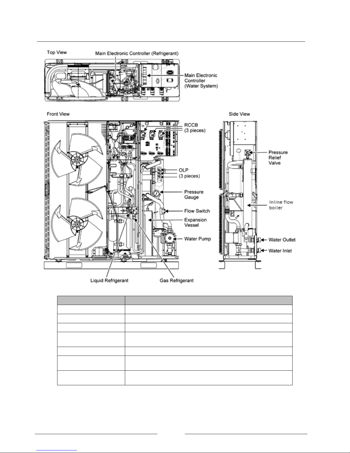
Section 9: Technical specification of the LA MI range
Component
Notes
Water Pump
Circulates water around the heating circuit.
Pressure Gauge
Gives the pressure of the water in the heating circuit.
Flow Switch
Checks the water flow in the heating circuit for efficient and safe operation.
Pressure relief valve
A safety device that relieves the pressure in the heating circuit if it exceeds
3 bar.
Inline flow boiler
Additional heating capacity for Bivalent operation.
OLP (Over load protection)
A safety device to prevent the inline flow boiler from overheating the
heating circuit.
Sledge
Two metal rails increase the structural integrity of the heat pump and
should not be removed.
Figure 24: Components of the LA 12 and 16 MI
Page 28
Page 28
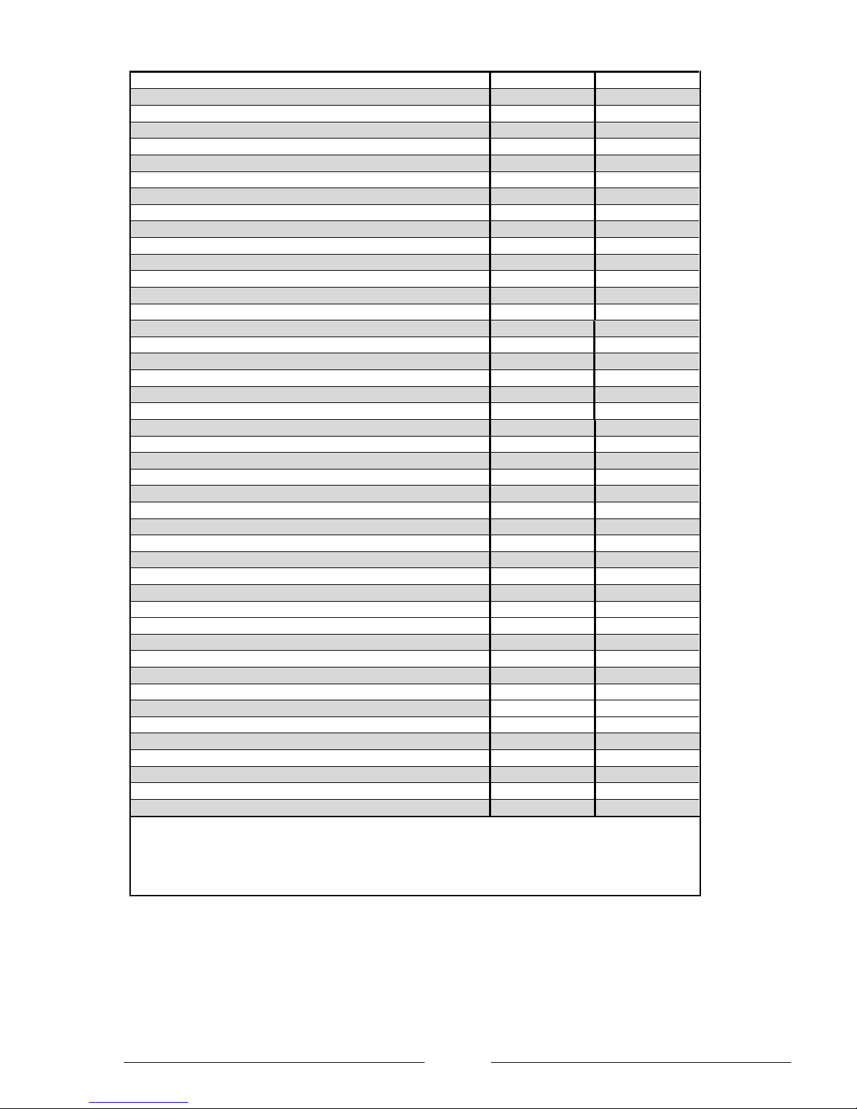
Performance Data
1
Type and order code
LA 6 MI
LA 9 MI
2
Design
2.1
Degree of protection according to EN 60 529 for a compact unit or heating element
IP 24
IP 24
2.2
Installation location
Outdoors
Outdoors
3
Performance Data
3.1
Operating temperature limits:
Heating water flow / return flow
°C
Max. 55 / min. 25
Max. 55 / min. 25
Air °C -20 to+35
-20 to+35
3.2
Heating water temperature difference
at A7 / W35
K
5
5
Heat output / COP (defrost)
at A7 / W35 1
kW / ---
6 / 4.4
9 / 3.9
at A2 / W35 1
kW / ---
5.5 / 3.5
7.6 / 3.1
at A-7 / W35 1
kW / ---
5.9 / 2.8
8.9 / 2.4
at A7 / W55
kW / ---
6 / 2.5
9 / 2.3
at A2 / W55
kW / ---
5.5/ 2.2
7.9 / 2.0
at A-7 / W55
kW / ---
5.8 / 1.8
7.6 / 1.5
Heat output / COP (peak)
at A7 / W35
kW / ---
6 / 4.4
9 / 3.9
at A2 / W35
kW / ---
6 / 3.7
9 / 3.4
at A-7 / W35
kW / ---
5.9 / 2.8
8.9 / 2.4
at A7 / W55
kW / ---
6 / 2.5
9 / 2.3
at A2 / W55
kW / ---
6 / 2.2
8.9 / 2
at A-7 / W55
kW / ---
5.8 / 1.8
7.6 / 1.5
3.3
A- weighted sound power level
dB(A) 58
61.5
3.4
Sound pressure level at 1m with Q=2 to MCS 020
dB(A) 54
54
3.5
Heating water flow rate
m³/h
1
1.6
3.6
Air flow m³/h 2800
3100
3.7
Refrigerant; total filling weight
Type / kg R410A / 1.45
R410A / 1.45
3.8
Lubricant; total filling quantity
Type / Litre FV50S (PVE)) / 0.9
FV50S (PVE)) / 0.9
4
Dimensions, connections and weight
4.1
Device dimensions without connections
H x W x L mm
860 x 1280 x 320
860
x
1280 x 320
4.2
Device connections to heating system
Inch 1 1/4" ext. thread
1 1/4" ext. thread
4.3
Weight of the transportable unit(s) incl. packaging
kg
122
122
5
Electrical Connection (Heat Pump)
5.1
Nominal voltage
V
230
230
5.3
Starting current
A N/A (Inverter driven)
N/A (Inverter driven)
5.4
Power factor MCCB 1 at A7 W35 / cos
A / --- 0.95
0.95
6
Back up heater nominal power consumption
kW
3.0
3.0
7
Heating Water Circuit
7.1
Expansion Vessel
Litre / Bar 6 / 3
6 / 3
7.2
Pressure Relief Valve
Bar Open 3.0 / Close 2.65
Open 3.0 / Close 2.65
7.3
Free pressure, heating circulating pump (max speed)
kPa
56
56
8
Other design characteristics
8.1
Defrosting
Automatic
Automatic
Type of defrosting
Reverse Cycle
Reverse Cycle
8.2
Heating water in device protected against freezing
yes
yes
8.3
Controller internal / external
External
External
1)
These data characterise the size and performance of the system according to EN 14511. Abbreviations have the following meaning,
e.g. A2 / W35: outside temperature 2°C and heating water supply temperature 35°C.
A2 / W35 test, takes into account defrosting as per
EN 14511.
2) According to EN 12102, EN ISO 3744.
Page 29
Page 29
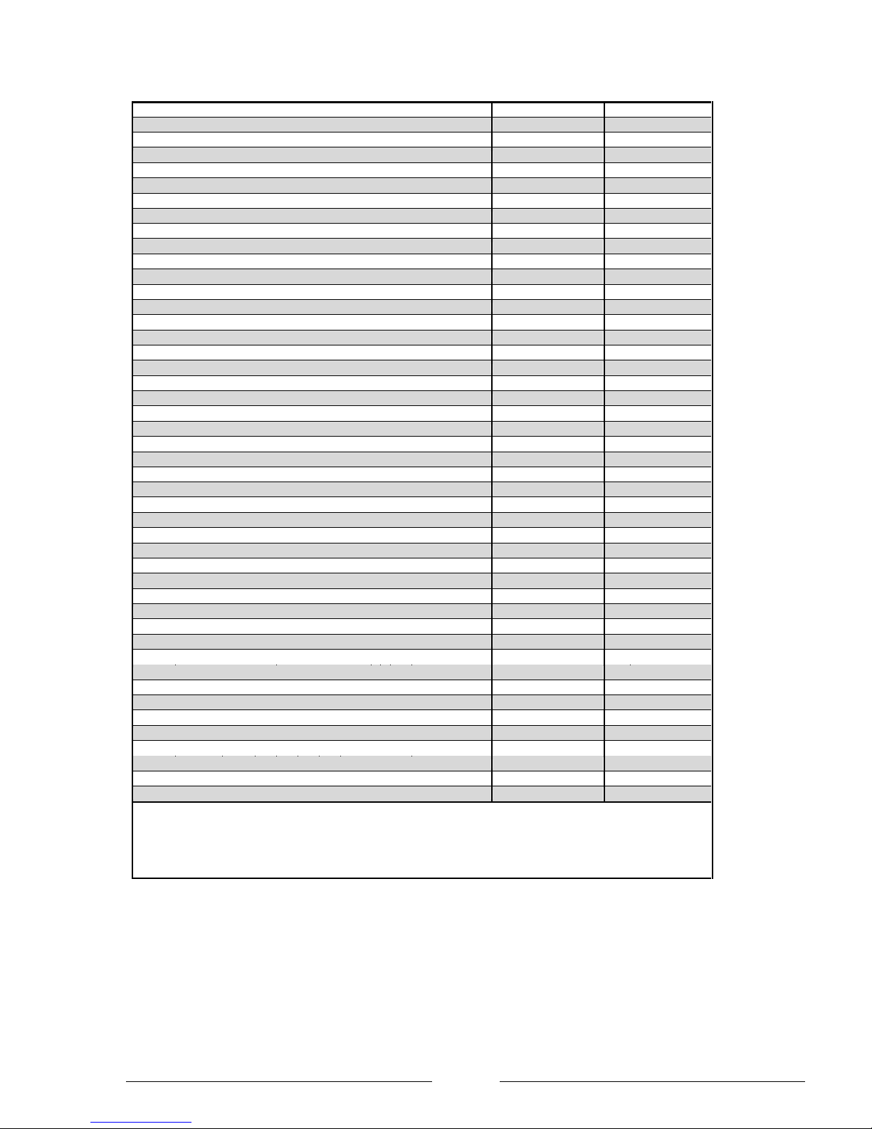
Performance Data
1
Type and order code
LA 12 MI
LA 16 MI
2
Design
2.1
Degree of protection according to EN 60 529 for a compact unit or heating element
IP 24
IP 24
2.2
Installation location
Outdoors
Outdoors
3
Performance Data
3.1
Operating temperature limits:
Heating water flow / return flow
°C Max. 55 / min. 25
Max. 55 / min. 25
Air °C -20 to+35
-20 to+35
3.2
Heating water temperature difference
at A7 / W35
K
5
5
Heat output / COP (defrost)
at A7 / W35 1
kW / --- 11.9 / 4.6
15.9 / 4.1
at A2 / W35 1
kW / --- 10.6 / 3.5
13.7 / 3.0
at A-7 / W35 1
kW / --- 12.3 / 2.9
13.8 / 2.7
at A7 / W55
kW / --- 11.1 / 2.9
12.9 / 2.5
at A2 / W55
kW / --- 9.2 / 2.3
10.6 / 1.9
at A-7 / W55
kW / --- 9.93 / 1.9
9.5 / 1.7
Heat output / COP (peak)
at A7 / W35
kW / --- 12 / 4.7
16 / 4.2
at A2 / W35
kW / --- 12 / 3.9
16 / 3.5
at A-7 / W35
kW / --- 11.7 / 2.9
14.1 / 2.7
at A7 / W55
kW / --- 12 / 2.9
14.5 / 2.7
at A2 / W55
kW / --- 12 / 2.5
12.5 / 2.3
at A-7 / W55
kW / --- 10.5 / 1.9
10.5 / 1.9
3.3
Sound power level
dB(A) 62
64
3.4
Sound pressure level at 1m with Q=2 to MCS 020
dB(A)
54
56
3.5
Heating water flow rate
m³/h
2.1
2.8
3.6
Air flow
m³/h 4800
5400
3.7
Refrigerant; total filling weight
Type / kg R410A / 2.3
R410A / 2.3
3.8
Lubricant; total filling quantity
Type / Litre FV50S (PVE)) / 1.2
FV50S (PVE)) / 1.2
4
Dimensions, connections and weight
4.1
Device dimensions without connections
H x W x L mm
1410 x 1280 x 320
1410 x 1280 x 320
4.2
Device connections to heating system
Inch 1 1/4" ext. thread
1 1/4" ext. thread
4.3
Weight of the transportable unit(s) incl. packaging
kg
165
165
5
Electrical Connection (Heat Pump)
5.1
Nominal voltage
V
230
230
5.2
Nominal power consumption 2 A7 W35
kW
2.6
3.9
5.3
Starting current
A N/A (Inverter driven)
N/A (Inverter driven)
5.4
Power factor MCCB 1 at A7 W35 / cos
A / --- 0.96
0.96
6
Back up heater nominal power
kW
6.0
6.0
7
Heating Water Circuit
7.1
Expansion Vessel
Litre / Bar 10 / 3
10 / 3
7.2
Pressure Relief Valve
Bar Open 3.0 / Close 2.65
Open 3.0 / Close 2.65
7.3
Free pressure, heating circulating pump (max speed)
kPa
83
83
8
Other design characteristics
8.1
Defrosting
Automatic
Automatic
Type of defrosting
Reverse Cycle
Reverse Cycle
8.2
Heating water in device protected against freezing
Yes
yes
8.3
Controller internal / external
External
External
1)
Abbreviations have the following meaning, e.g. A2 / W35: outside temperature 2°C and heating water supply temperature
35°C.
A2 / W35 test, takes into account defrosting as per EN 14511.
2) According to EN 12102, EN ISO 3744.
Page 30
Page 30
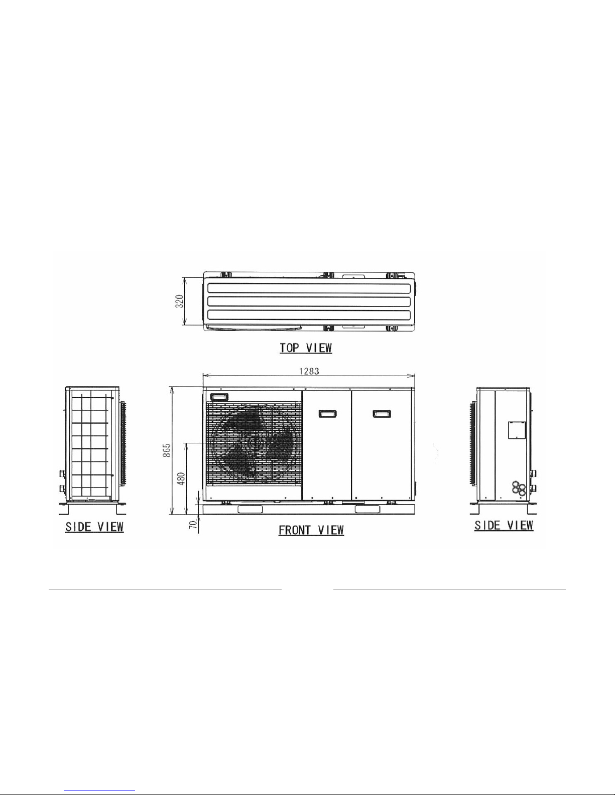
Product Dimensions LA 6 MI and LA 9 MI
Page 31
Page 31
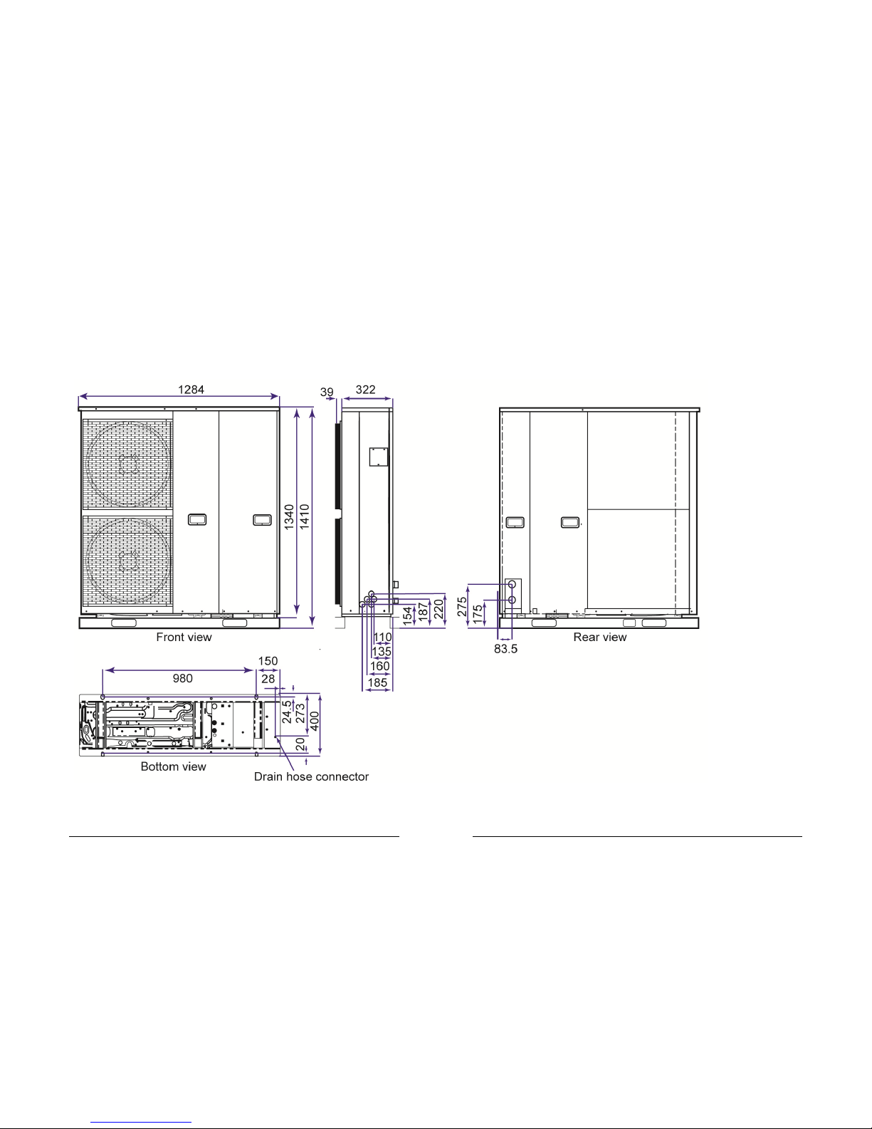
Product Dimensions LA 12 MI and LA 16 MI
Page 32
Page 32
Section 10: Annual System Health checks
The following items should be verified to ensure
efficient operation of the system:
Heat pump
Check the fan is clear from debris.
Check there is no abnormal sound during
operation.
Electrical
Power cable is firmly fixed.
Earth wire connection is secure.
RCCB operation is normal.
Supply voltage is correct.
Hydraulic
Water pressure higher than 1 bar.
Pressure relief valve operation is normal.
The filter is clear of debris.
Check entire system for leaks.
Cylinder
Set temperature is correct for efficient
operation.
Check the high temperature cut out stat on the
cylinder immersion and inline flow boiler have
not tripped.
Temperature and pressure relief is operating
correctly.
For full maintenance details for the cylinder consult the
relevant instruction manual.
Wall mounted thermostat
The set temperatures and heating periods are
suitable for the occupants life style.
Heat pump controller
LCD control panel operation is normal.
Enquire if the user is warm enough and reduce
the weather compensation curve to maximise
the heat pump efficiency.
Before opening the device, ensure that
all circuits are isolated from the power
supply.
Never use cleaning agents containing
sand, soda, acid or chloride as these
can damage the surfaces.
Any work on the heat pump may only be
performed by authorised and qualified
after-sales service technicians.
Page 33
Page 33
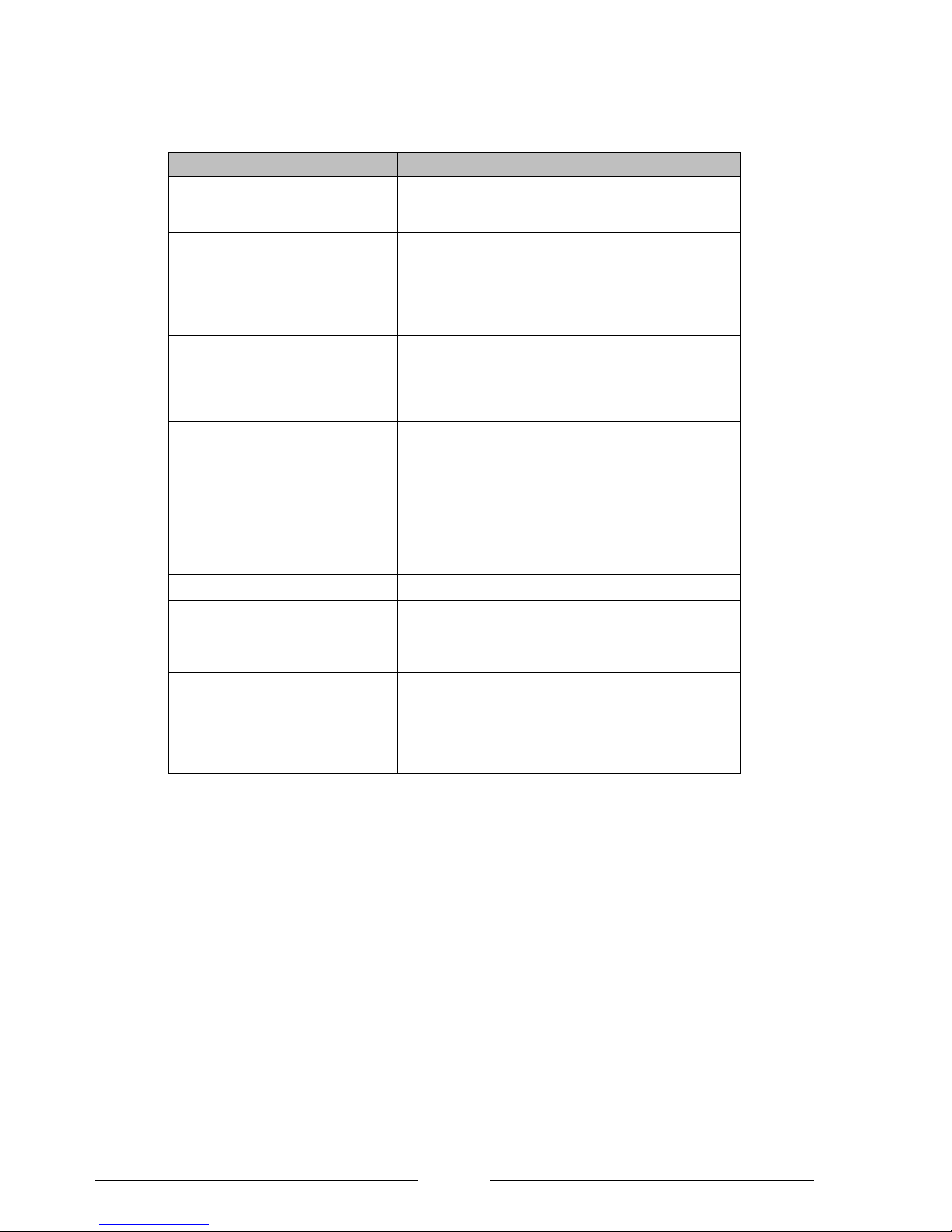
Section 11: Trouble shooting for the installer
Symptom
Cause
Heat pump emits mist
This is normal during certain atmospheric conditions
because the drop in air temperature caused by the
heat pump is cold enough for mist to form.
Heat pump does not operate
If the external temperature is above the HEAT OFF (in
advanced settings menu) the heat pump will not
operate.
If the water inlet temperature is lower than 20°C the
inline flow boiler will activate to raise the temperature.
Property does not heat-up enough
Heat pump undersized for the heat demand of the
property at low external temperatures.
Water flow temperature is set too low for the heat
emitters installed.
Property does not heat up quickly
Heat pumps are designed for continuous operation
and there is typically not a large overload factor to
heat the building quickly. The property temperature
should not be allowed to significantly drop during
periods of cold weather.
System is noisy during operation
Check the unit is not installed on an incline
Check the covers are closed correctly.
The controller is blank
Check the circuit breaker to the heat pump.
The hot water cylinder is cold
Check that the controller is in TANK mode
The hot water cylinder is not hot
enough
Check that the coil is correctly sized for the heat
pumps output.
Check that the temperature setting within the
controller is set to 45C.
Ice has formed on the heat pump
Ice formation on the evaporator is normal during cold
weather. The defrost function should keep the majority
of the coil clear of ice to allow adequate air flow.
Typically if the ice is less than 1cm thick and the
controller does not show a fault the system is
operating correctly.
Page 34
Page 34
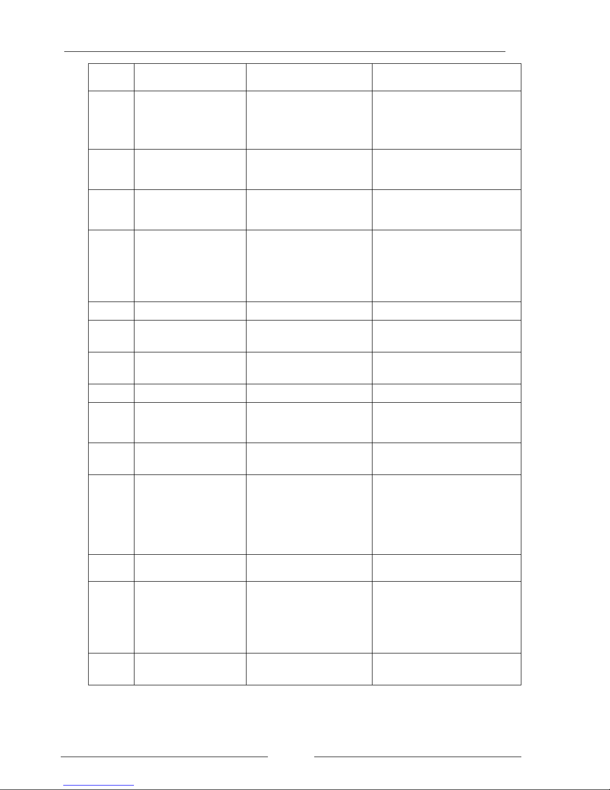
Section 12: Error codes
Diagnosis
display
Abnormality / Protection
control
Abnormality Judgement
Primary location to verify
H12
Indoor/Outdoor capacity
unmatched
90s after power supply
• Indoor/outdoor connection wire
• Indoor/outdoor PCB
• Specification and combination table in
Catalogue
H15
Outdoor compressor
temperature sensor
abnormality
Continue for 5 sec.
• Compressor temperature sensor
(defective or disconnected)
H23
Indoor refrigerant liquid
temperature
sensor abnormality
Continue for 5 sec.
• Refrigerant liquid temperature sensor
(defective or disconnected)
H42
Compressor low pressure
abnormality
• Outdoor pipe temperature sensor
• Clogged expansion valve or strainer
• Insufficient refrigerant
• Outdoor PCB
• Compressor
H62
Water flow switch abnormality
Continue for 1 min.
• Water flow switch
H64
Refrigerant high pressure
abnormality
Continue for 5 sec.
• Outdoor high pressure sensor
(defective or disconnected)
H70
Back-up heater OLP
abnormality
Continue for 60 sec.
• Back-up heater OLP
(Disconnection or activated)
H72
Tank sensor abnormal
Continue for 5 sec.
• Tank sensor
H76
Indoor - remote control
communication
abnormality
• Indoor - control panel
(defective or disconnected)
H90
Indoor / outdoor abnormal
Communication
> 1 min after starting operation
• Internal / external cable connections
• Indoor / Outdoor PCB
H91
Tank heater OLP abnormality
Continue for 60 sec.
• Domestic hot water cylinder high limit
stat or temperature thermostat
disconnection or activated.
• Check thermostat is set to maximum
temperature on the cylinder.
•Test for continuity between pins13 and
14 at the heat pump.
H95
Indoor/Outdoor wrong
connection
• Indoor/Outdoor supply voltage
H98
Outdoor high pressure
overload
protection
• Outdoor high pressure sensor
• Water pump or water leakage
• Clogged expansion valve or strainer
• Excess refrigerant
• Outdoor PCB
H99
Indoor heat exchanger freeze
prevention
• Indoor heat exchanger
• Refrigerant shortage
Page 35
Page 35
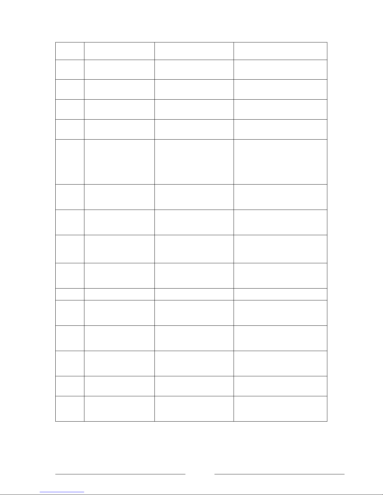
Diagnosis
display
Abnormality / Protection
control
Abnormality Judgement
Primary location to verify
F12
Pressure switch activate
4 times occurrence within 20
minutes
• Pressure switch
F14
Outdoor compressor abnormal
revolution
4 times occurrence within 20
minutes
• Outdoor compressor
F15
Outdoor fan motor lock
abnormality
2 times occurrence within 30
minutes
• Outdoor PCB
• Outdoor fan motor
F16
Total running current
protection
3 times occurrence within 20
minutes
• Excess refrigerant
• Outdoor PCB
F20
Outdoor compressor
overheating
protection
4 times occurrence within 30
minutes
• Compressor tank temperature sensor
• Clogged expansion valve or strainer
• Insufficient refrigerant
• Outdoor PCB
• Compressor
F22
IPM (power transistor)
overheating
protection
3 times occurrence within 30
minutes
• Improper heat exchange
• IPM (Power transistor)
F23
Outdoor Direct Current (DC)
peak
detection
7 times occurrence continuously
• Outdoor PCB
• Compressor
F24
Refrigeration cycle
abnormality
2 times occurrence within 20
minutes
• Insufficient refrigerant
• Outdoor PCB
• Compressor low compression
F25
Cooling / Heating cycle
changeover
abnormality
4 times occurrence within 30
minutes
• 4-way valve
• V-coil
F27
Pressure switch abnormality
Continue for 1 min.
• Pressure switch
F36
Outdoor air temperature
sensor
abnormality
Continue for 5 sec.
Outdoor air temperature sensor
(defective or disconnected)
F37
Indoor water inlet temperature
sensor
Abnormality
Continue for 5 sec.
Water inlet temperature sensor
(defective or disconnected)
F40
Outdoor discharge pipe
temperature
sensor abnormality
Continue for 5 sec.
• Outdoor discharge pipe temperature
sensor (defective or disconnected)
F41
PFC control
4 times occurrence within 10
Minutes
• Voltage at PFC
F42
Outdoor heat exchanger
temperature
sensor abnormality
Continue for 5 sec.
• Outdoor heat exchanger temperature
sensor (defective or disconnected)
Page 36

Page 36
Diagnosis
display
Abnormality / Protection
control
Abnormality Judgement
Primary location to verify
F43
Outdoor defrost sensor
abnormality
Continue for 5 sec.
• Outdoor defrost sensor (defective or
disconnected)
F45
Indoor water outlet
temperature sensor
Abnormality
Continue for 5 sec.
• Water outlet temperature sensor
(defective or disconnected)
F46
Outdoor Current Transformer
open
Circuit
-
• Insufficient refrigerant
• Outdoor PCB
• Compressor low
F95
Cooling high pressure
overload
protection
-
• Outdoor high pressure sensor
• Water pump or water leakage
• Clogged expansion valve or strainer
• Excess refrigerant
• Outdoor PCB
Page 37

Page 37
Section 13: Standard packages
To assist with the design and installation of a
system Dimplex have collated wiring and hydraulic
schematics for the following designs:
Package 1 and 2
Heating and Domestic hot water preparation is
done using the heat pump.
Buffer cylinder is supplied either in a combined
buffer/DHW cylinder (pack 1) or as a standalone
buffer (pack 2)
2 x two port valves are used to switch between
heating and DHW preparation.
Room temperature is time and temperature
controlled using the Horstmann wall mounted
thermostat. The thermostat will create a demand if
the temperature drops below 15C whilst the
system is off to prevent the base temperature
dropping too low.
DHW temperature is measured via NTC2 sensor
and time of production is set using the Heat pump
controller.
Includes a Taconova flow checker for efficient
setup and isolation valves with inbuilt filter to
ensure debris is removed.
Package 3
Package for space heating only. No hot
water cylinder is included.
Buffer cylinder is supplied to ensure
minimum water volume.
Room temperature is time and
temperature controlled using the
Horstmann wall mounted thermostat. The
thermostat will create a demand if the
temperature drops below 15C whilst the
system is off to prevent the base
temperature dropping too low.
Includes a Taconova flow checker for
efficient setup and isolation valves with
inbuilt filter to ensure debris is removed.
Page 38
Page 38
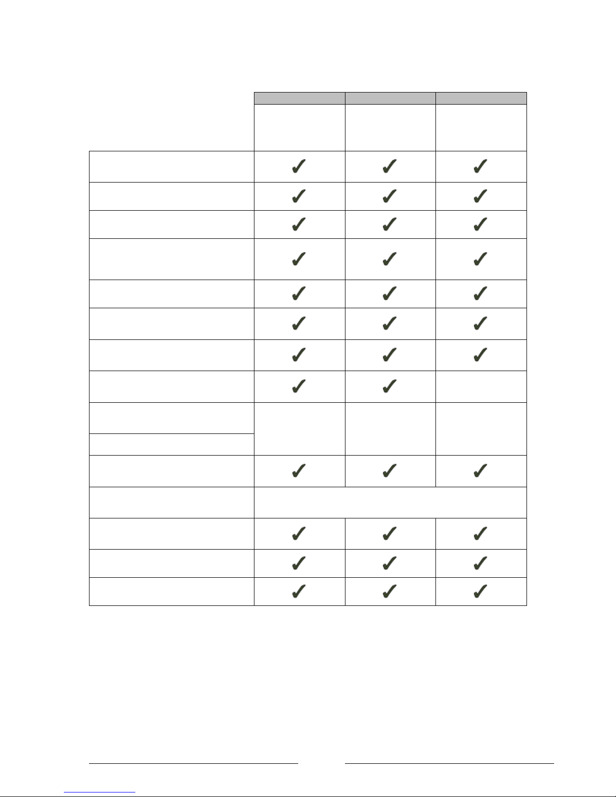
Suggested additional components
Pack 1
Pack 2
Pack 3
1 heating zone and
DHW with combined
buffer and DHW
cylinder
1 heating zone and
DHW with separate
buffer and DHW
cylinder
1 heating zone with
buffer tank
Concrete base, fixing bolts, condensate
drain method
Interconnecting pipe work
Ducting for wiring and pipe work
Chemicals for cleaning existing pipe
work and standard corrosion inhibitors
for central heating systems
Air purge valves at every high point
Isolation switch for isolation of heat
pump during maintenance
Multi core cable for connection of wiring
centre to heat pump
2 core cable for connection of DHW
sensor
No
3 core cable for connection of DHW
immersion heater to heat pump
Depends upon
schematic. Either
cable or relay
required.
Depends upon
schematic. Either
cable or relay
required.
No
Relay for switching immersion heater
3 core cable for mains supply from
Distribution board to Isolation switch.
Expansion vessel
An expansion internal vessel is supplied, an addition one may be
required depending upon system volume.
Flushing & Filling point / Drain down
point
Bypass for heating circuit
Heat emitters
Table 6: Components not supplied by Dimplex but required to complete the installation.
Page 39
Page 39
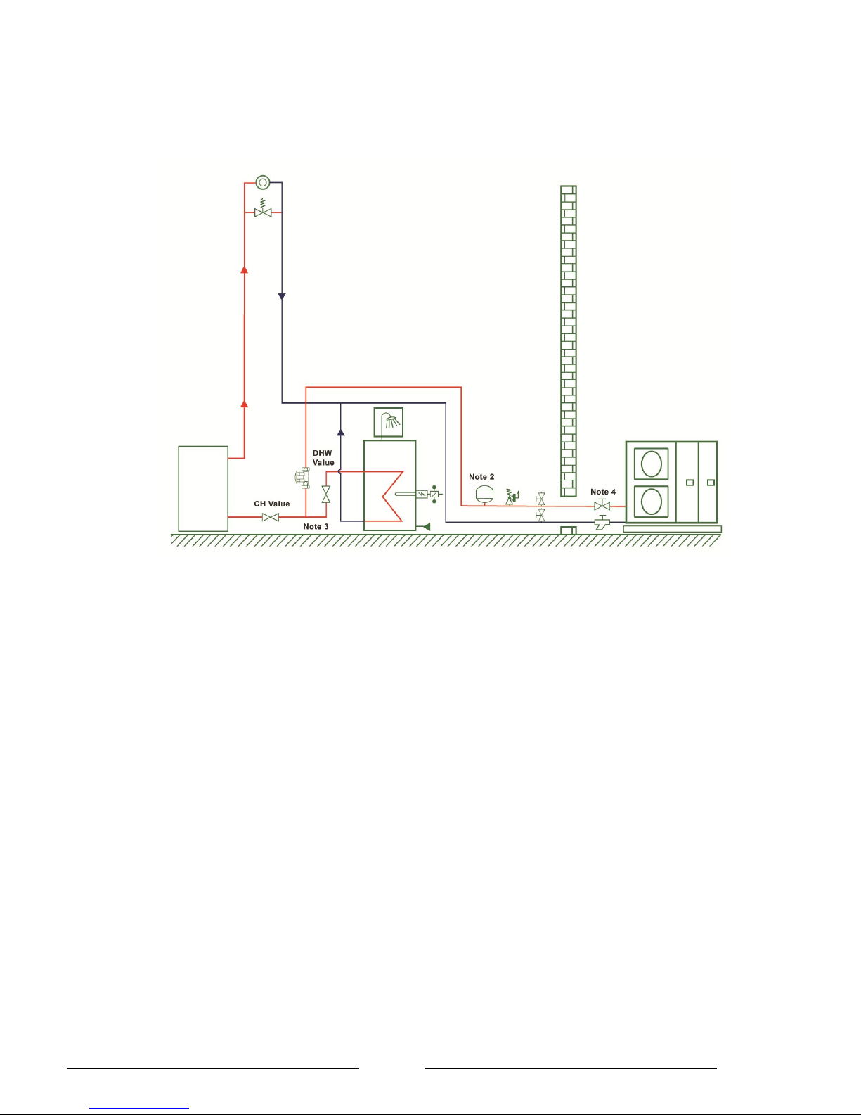
Package 1 and 2 – Plumbing Schematic
1 x heating zone, buffer and DHW cylinder, DHW immersion powered by heat pump
Notes:
1. Air bleed valves must be installed at every high point.
2. Depending upon the system volume an expansion
vessel may be required in addition to the one already
installed in the LA MI
3. When using a Dimplex Ec-Eau cylinder with an Air-Eau
heat pump it is not necessary to install a separate 2 port
value for G3 compliance.
4. It is a condition of the Guarantee that the filter
(supplied in the heat pump packages) is fitted prior to the
heat pump inlet.
5. Connections should be provided so that the system
can be flushed of debris, filled and then purged of air
without passing debris through the heat pump.
`
Page 40
Page 1
User’s guide to an Air-eau heat pump system
How the heat system works
The heat pump takes renewable energy from the
surrounding air and converts it into usable heat. For
every 1kW of electrical energy the heat pump uses it will
extract approximately 3kW of energy from the outside air
making it 400% efficient which reduces carbon emissions
and money off your fuel bills!
How to operate your system efficiently
To operate the system in the most efficient way:
Keep the room temperature as low as possible
and turn the heating to set back when the
property is not occupied.
If the property has an off-peak tariff check with
your installer that they have set the DHW
recovery and sterilisation to happen during offpeak times.
Store the domestic hot water at a lower enough
temperature so the immersion is not required to
heat the Domestic hot water.
Keep power to the unit
The power should never be turned off except for
maintenance since the water in the external parts of the
heat pump are liable to freezing during cold weather. This
would lead to permanent irreparable damage to the heat
pump.
The heat pump is designed to operate extremely
efficiently all the time and should not be turned off at
night time, over summer or when you are away from the
house.
System health check
Your installer should have left you with a log book that
contains all the information required for your annual
system health check. If this is missing please contact
Dimplex customer care.
What to do if your system stops working
If anything goes wrong with the heat pump you should try
to solve the problem using the trouble shooting guide
below. If this is not successful you should contact
Dimplex customer care for technical support over the
phone. If the problem cannot be resolved over the phone
you should contact your installer.
INSERT INSTALLER
DETAILS HERE
Advanced operation
At the commissioning stage the installer will set-up the
advanced settings. If the user needs to change any of the
following settings they should consult the installation
manual.
System flow temperature and weather
compensation.
Temperature of the DHW cylinder
Users Troubleshooting guide
Hot water cylinder
is cold
Check the system setting controller
is in TANK mode.
Heating circuit is
cold
Check the system setting controller
is in HEAT mode.
Rooms are not
warm enough
Check the heat emitters are on
Check they were turned on early
enough.
No hot water or
space heating
Check the heat pump controller:
Ensure the green light is on.
Check for an error number and
contact your installer.
Heat pump
outside drips
water or emits
steam
This is a normal process during
cooler weather and is nothing to
worry about.
The amount of heat that the system can
output is closely matched to the maximum
load of the property. For this reason, the if
the blue button is pressed on the Central
heating controller you should be aware it
will take a long time to recover the room
temperature from a cold start, especially
during periods of extremely cold weather.
Page 41
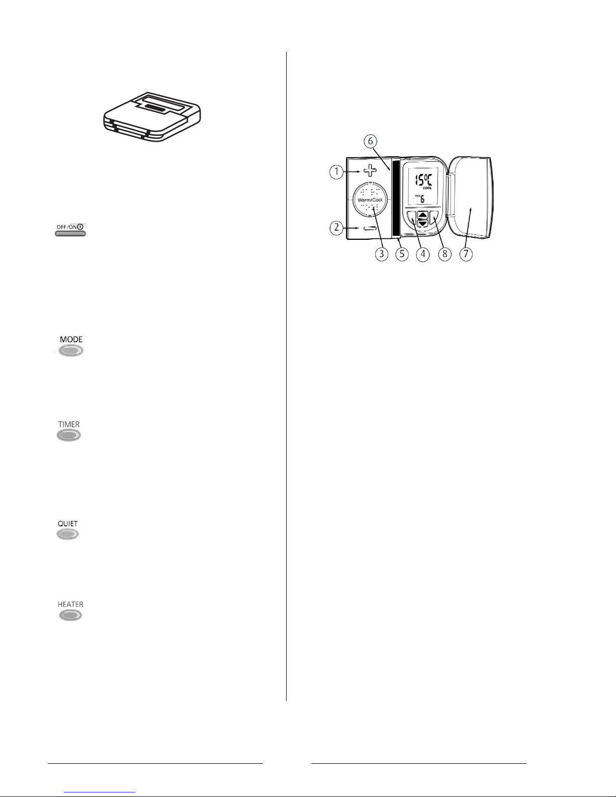
Page 2
Adjusting the heat pump
OFF/ON Standby Button
When the unit is ON, the operation LED is
lit and the compressor will operate when
required. When in standby the
compressor will not operate however the
circulation pump and inline flow boiler can
be activated to provide frost protection.
The green LED should remain on at all
times.
Operation Mode Button
Press the mode button to cycle through
the following options. A block will be
displayed against the appropriate text on
the controller‟s screen.
1. HEAT ONLY
2. HEAT + TANK
3. TANK ONLY
Setting the DHW timer schedules
If required, the DHW production times
can be adjusted by pressing the „timer „
button. Consult the installation
instructions to find out how to set the time
periods.
Quiet Operation Button
If pressed, this will reduces the noise of
the heat pump by This will affect the COP
and kW output. This feature can be set up
on the “timer”. Consult the installation
instructions for more information.
Boosting the amount of space heating
During periods of cold weather, or if you
require the property to be heated up
quickly, the boost button can be pressed
on the wall mounted controller. The boost
heater will automatically turn off once the
property is up to temperature.
During an error the system will use an electric flow boiler
to keep the property warm – this will have higher running
costs compared to the heat pump. The user should
regularly check the system controller for error such as
H91. In the event of an error you should contact your
installer.
Adjusting the central heating
The central heating is controlled using the wall mounted
thermostat shown below. You should press the large
buttons to adjust the room temperature.
Increasing the room temperautre
If the red lights are not on, press the „Warm / Cool‟ button
(3). The blue light means the unit is working on the set
back temperature. The „+‟ or „-„ buttons do not work when
the thermostat is in setback.
When one or more red lights are on, you can increase the
temperature by pressing the „+‟ button (1). For example,
press once to go up by 1 degree C, or press twice to go
up by 2 degrees C.
Decrease the room temperature
When the two or three red lights are on, the temperature
can also be lowered to the centre position by using the „-„
button (2).
‘Short’ heating off periods
If you are going to bed or going out for the day you can
turn the heading off by using the „Warm / Cool‟ button (3)
until the blue lights come on. The heating will
automatically come back on during the next time period.
‘Long’ off periods
If you want to turn the heating off long periods such as
you are going on holiday or during summer you press the
blue button (4) under the flap (7). When you want to go
back to normal operation they will open the flap and
press the Blue button again.
Time periods
The wall thermostat will automatically adjust between
heating and set back temperatures. If you adjust the
temperature using the large buttons the temperature will
revert back to the pre-set value when the next time period
starts. To change the time periods consult the PRT1
manual.
Page 42
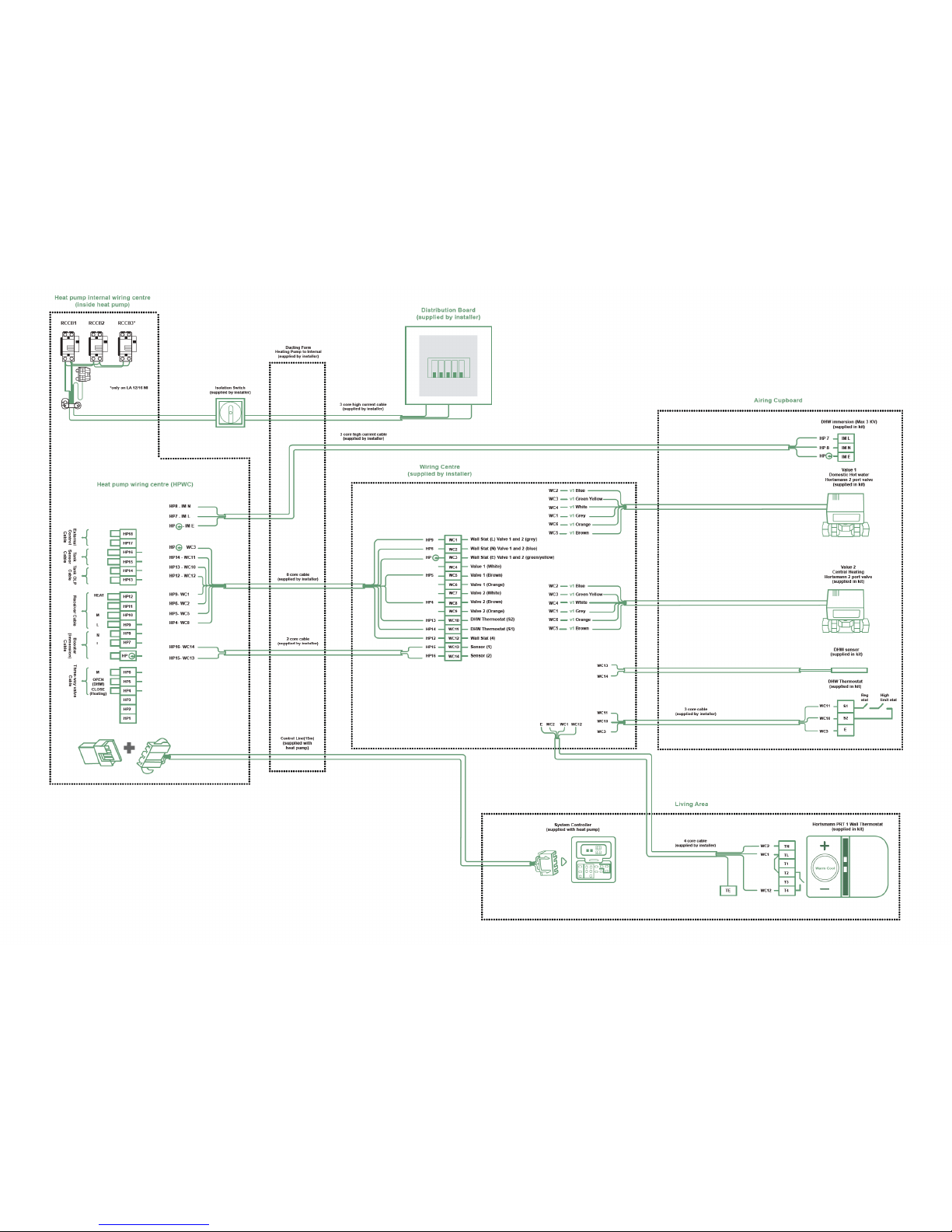
 Loading...