

Page 1
Installation and Operating Manual
Heat Pump for Cooling of Domestic Water
with Airduct Connection
KWP 300
451902.67.39 FD8411
Page 2

2
TABLE OF CONTENTS
Page
1. Regulations / Safety Notices 3
2. Description 4
2.1 Refrigeration Cycle 4
2.2 Water Circuit 4
2.3 Safety and Control Devices 5
3. Storage / Transport 6
3.1 General Requirements 6
4. Installation 6
4.1 Installation Site 6
4.2 Installation 7
5. Mounting 7
5.1 Connection of Water Piping 7
5.2 Electrical Connection 8
6. Commissioning 8
6.1 Domestic Water Circuit 8
6.2 Operation of the Heat Pump for Cooling of Domestic Water 9
7. Maintenance / Service 10
7.1 Water Circuit 10
7.2 Air Circuit 10
7.3 Sacrificial Anode 11
8. Malfunctions / Troubleshooting 12
9. Decommissioning 12
10. Environmental Requirements 12
11. APPENDIX
11.1 Refrigeration Cycle with Legend 13
11.2 Hydraulic Plumbing Diagram 14
11.3 Circuit Diagram 15
11.4 Technical Data 16
(
HPCDW = abbreviation used in the following for Heat Pump for Cooling of Domestic Water
)
Page 3

3
1. Regulations / Safety Notices
(
This installation and operating manual must be read prior to starting up the unit !
)
¾¾¾¾####
The heat pump for cooling of domestic water (short: HPCDW) is designed exclusively for the cooling (in part
also for the heating) of domestic or potable water within the specified operating temperature limits! The cooling
(or heating) of liquids other than drinking water is not permissible. The technical regulations for the drinking
water installation (DIN 1988) must be adhered to.
¾¾¾¾####
The air supplied to the unit should not exceed a temperature of +45 °C. The energy-efficient operation of the
heat pump decreases as the air temperature increases.
¾¾¾¾####
The following is not permitted:
- operation using exhaust air posing an explosion hazard or containing solvents
- use of exhaust waste air laden with grease, dust or sticking aerosols
- connection of exhauster hoods to the ventilation system
¾¾¾¾####
The unit must not be installed:
- outdoors
- in rooms with a danger of freezing
- in wet rooms (e.g. bathrooms)
- in room with an explosion hazard due to gases, vapours or dust
¾¾¾¾####
The operation of the unit is not permitted:
- with empty storage tank
- during the construction phase
¾¾¾¾
In the design and construction of the HPCDW all relevant EC directives were complied with. (See also EC
Declaration of Conformity.)
¾¾¾¾
The qualified expert must ensure that prior to the commencement of any maintenance/repair activities on
refrigerant-carrying parts, the refrigerant has been removed to such an extent as necessary for the safe
performance of this work. The refrigerant must be handled and disposed of in accordance with applicable
regulations and must not be released into the atmosphere! (Refrigerant R134a is CFC-free, non-flammable
and has no ozone-depleting properties.)
¾¾¾¾####
When working on the HPCDW, the unit must always be disconnected from the power source.
¾¾¾¾####
The electrical connection of the HPCDW must be performed according to and conforming with all relevant
VDE, EN and IEC standards. Beyond that, the technical connection requirements of the local utility company
have to be observed.
Caution!
Any work on the cooling/domestic water heat pump may only be performed by qualified persons! All
relevant accident prevention regulations have to be observed !
Page 4
4
2. Description
The
HPCDW
is a domestic water cooling unit ready for connection and essentially consists of a domestic water
tank, the components of the refrigeration, air and water circuits as well as all control, regulating and monitoring
devices required for automatic operation.
In accordance with the heat pump's principle of operation, unwanted heat is extracted from the domestic water and
then transferred to the discharged outlet air.
The unit is equipped as standard with an electric immersion heater (1.5 kW) which enables domestic water to be
heated (up to a temperature of max. 85 °C) (heating function).
2.1 Refrigeration Cycle
(Heat Pump Principle of Function)
The refrigeration cycle is a closed system in which the refrigerant R134a circulates as an energy carrier. In a
tubular evaporator wrapped around the domestic water tank, heat is extracted from the domestic water at a low
evaporation temperature and transferred to the refrigerant. The vaporous refrigerant is drawn in by an electrically
driven compressor and compressed to a higher pressure/temperature level and then passed to the condenser (fintype heat exchanger), where the heat that is absorbed in the tubular evaporator and part of the heat of the
compressor motor is transferred to the drawn-in exhaust air. Subsequently, the high condensing pressure is
reduced by means of a throttling device (expansion valve) to the level of the evaporating pressure, and the
refrigerant can again absorb heat from the domestic water tank via the tubular evaporator.
2.2 Water Circuit
The water circuits of the
HPCDW
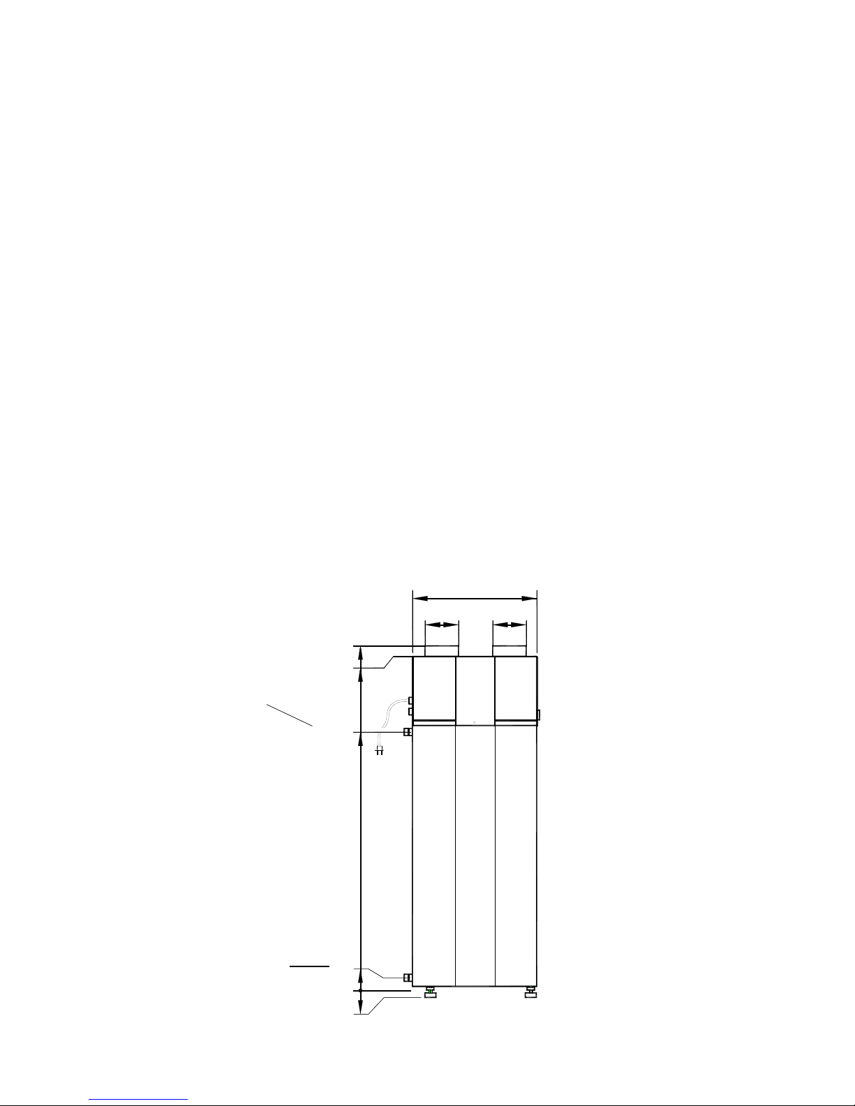
are to be field-installed (by the customer). The water connections (Fig. 1) are
located at the rear of the unit.
Fig. 1: Water connections
Brauchwasserzulauf
R1" Außengewinde
Brauchwasserentnahme
R1" Außengewinde
20 - 35
0
1226
55
1620
1660
Ø
160
Ø
160
660
Domestic water supply
external thread R1“
Domestic water outlet tap
external thread R1“
Page 5
5
2.3 Safety and Control Devices
The HPCDW is equipped with the following safety features:
2.3.1 High-pressure pressostat (HD)
The high-pressure pressostat protects the heat pump from excessive operating pressures in the refrigeration cycle.
In the case of a malfunction, the pressostat switches off the heat pump; the heat pump is restarted automatically as
soon as the pressure in the refrigeration cycle has dropped to an acceptable level.
2.3.2 Safety temperature limiter for immersion heater (STL)
The STB protects the hot water installation from
excessive temperature increases.
When the preset switching value (99 °C) is exceeded, the
immersion heater is switched off.
The immersion heater cannot be restarted unless the hot
water temperature has fallen to ≤ 90 °C and the reset
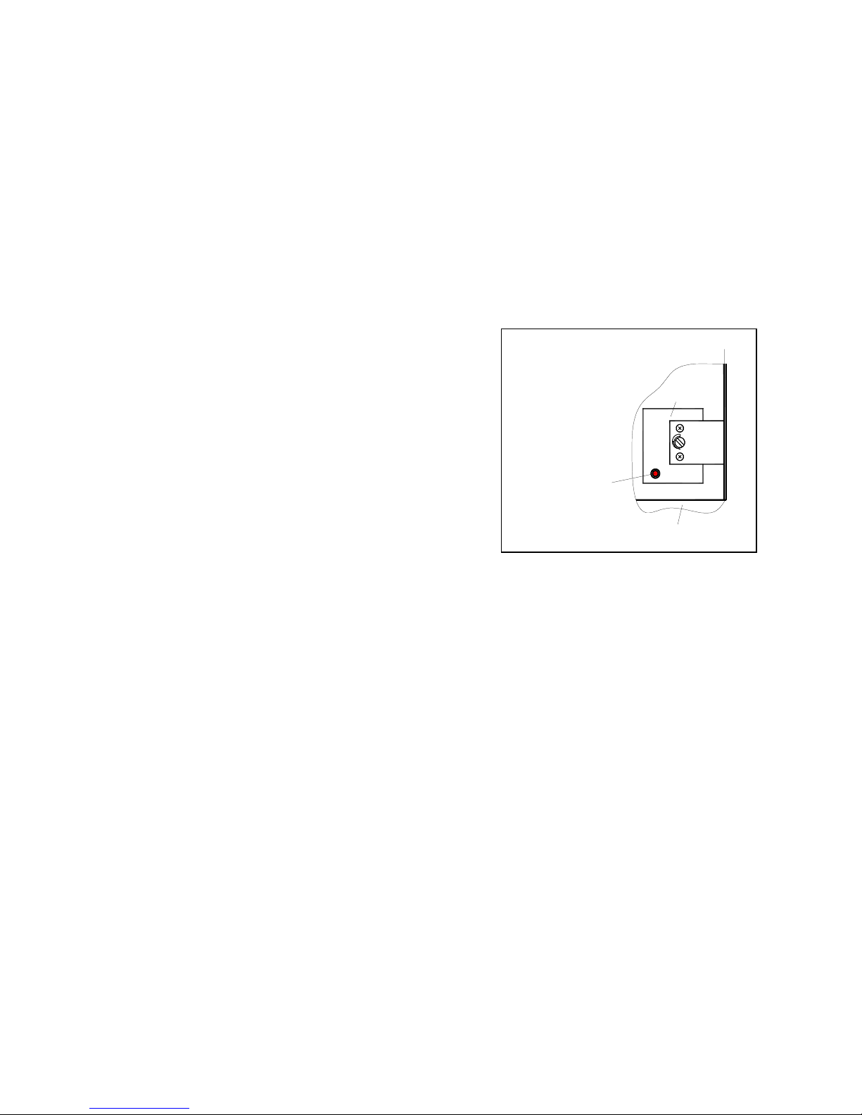
button (Fig. 2) on the STB has subsequently been
pressed (may be performed by qualified personnel only!).
Fig 2: Resetting STL
2.3.3 Temperature controller for immersion heater (TC)
The temperature controller for the immersion heater controls the temperature of the water for domestic use during
the immersion heater mode of operation. The maximum temperature of this controller has been factory-set to 65 °C
(the controller is installed with the STL in a common casing). The temperature setting can be changed with the aid
of a suitable tool (see Fig. 2). Changing this setting may be performed by qualified persons only!
In the immersion heater mode, which can only be turned on manually, the domestic water is heated up to the
preset maximum temperature of the immersion heater.
2.3.4 Temperature controller of HPCDW
Temperature control in the domestic water storage tank and the control of the compressor operation is taken over
by the temperature controller. The latter senses the water temperature by means of a sensor and regulates it as a
function of the preset setpoint. The desired temperature level (setpoint) can be adjusted via the dial on the
operating panel.
85°
30°
B3
F2
STB
Partition
Panel
Reset button
Page 6

6
3. Storage and Transport
3.1 General Requirements
As a rule, the CWP is to be stored or transported in its shipping box in upright position and
without water charge
.
For a transport over short distances, and provided due care is exercised, an inclination angle of up to 45° is
permitted. Both during transport and storage, ambient temperatures of -20 to +60 °C are permissible.
3.1.1 Transport using a forklift
(or lift truck)
When transported by a fork lift, the HPCDW must remain mounted on the pallet. The lifting rate should be kept to a
minimum. Due to its top-heaviness, the HPCDW must be secured against tipping over. To prevent any damage, be
sure to place the HPCDW on a level floor.
3.1.2 Manual transport
For the manual transport, the wooden pallet can be used for the bottom part. Using ropes or carrying straps (which
can be placed around the jacket of the storage tank and secured to the water tube nipples), a second or third
handling configuration is possible. With this type of handling (applies to the transport by hand truck as well), care
must be taken that the
max. permissible inclination angle of 45°
is not exceeded (see Figure). If transport in an
inclined position cannot be avoided, the HPCDW ("heat pump" switch) should be taken into operation one hour
after it has been moved into final position at the earliest.
Caution! Do not lift the unit by its cover
(the cover is not designed to withstand the weight of the unit !)
4. Installation
4.1 Installation Site
CAUTION!
¾#
The HPCDW must be sited in a
dry and freeze-proof room
, the room air temperature and/or the air taken in
by the HPCDW must be within a temperature range of 20°C to 45 °C (required for heat pump operation).
¾#
In addition, the unit
must not
be installed in rooms where there is an explosion hazard due to gases, vapours
or dust.
¾#
The air drawn in must be not excessively contaminated or heavily laden with dust.
¾#
The floor surface must have adequate load bearing capability (the estimated HPCDW weight is 400 kg when
fully loaded!).
For trouble-free operation as well as for the performance of maintenance and repair work, provide clearance of at
least 0.6 m all around the unit, furthermore, a minimum ceiling height of approx.
2.50 m
is required
for operation
without airducts or airduct elbows
(➠"free-blowing“ installation“) (see Fig. 4). The connection to the HPCDW is
effected (optionally) by means of airducts (NW 160) which must not exceed a
total
length of 10 m.
Fig. 3: Transport of the unit
°
Page 7

7
If the ceiling is lower and no airducts are used, an air ducting elbow (90° NW 160) must be used on the
outlet air side (to ensure effective operation). When an air ducting elbow is used, care must be taken that it is
slipped onto the flange collar of the discharge side in such a way that the discharge opening of the air ducting
elbow is as far away from the intake opening of the unit as possible. Moreover, the minimum clearances shown in
Figure 4 have to be complied with. The air connection fittings, i.e. "intake pipe" and "discharge pipe", of the
HPCDW
are identified by adhesive labels.
Fig. 4: Installation requirements
4.2 Installation
¾
From the underside of the pallet, remove the three M12 bolts securing the pallet to the unit as a shipping safety
measure.
¾
Remove the pallet and mount the three levelling feet (M12 bolts – contained in the polybag, secured to the
storage tank pipe nipple).
¾
Move the HPCDW into final position and adjust the unit so that it is perfectly perpendicular by adjusting the
levelling feet! Subsequently, tighten the check nuts provided on the levelling feet.
5. Mounting
5.1 Connection of Water Piping
The nominal pipe widths of the field-installed sanitary installations must be determined on the basis of the available
water pressure and the expected pressure losses within the piping system.
The water-side
installation
has to be executed in compliance with DIN 1988 (see appendix – in the case of
excessive water pipe pressure, a pressure relief valve is to be provided, among other things !)
The water pipes may be of the rigid or flexible type. To prevent corrosion damage, make sure that the materials
used in the piping system are compatible (see section Commissioning).
Caution! When installing the pipework on the customer's site, any contamination of the piping system
must be avoided (pipes may have to be flushed prior to the connection of the HPCDW)!
* the minimum distance of
the discharge opening of
the air ducting elbow
to the wall is 1.2 m
The minimum ceiling
height for "free blowing
installation" is approx.
angesaugte Luft
ausgeblasene
Luft
1,2 * m
0,6 m
ca. 2,0 m
ca. 2,5 m
(ohne Luftschläuche und Luftführungsbogen)
discharged
drawn-in air
approx. 2.0 m
approx. 2.5 m (without airducts and air ducting elbow)
Page 8

8
5.2 Electrical Connection
The HPCDW is pre-wired, ready for connection, the power is supplied via the mains cable connected to a socket
with earthing contact (GB: "Home Office socket") (~230 V, 50 or 60 Hz). This socket must be accessible also after
the installation has been completed.
6. Commissioning
6.1 Domestic Water Circuit
➨➨➨➨
Caution!
The HPCDW may only be operated with the unit filled with water!
6.1.1 Water circuit requirements
On the consumer side, the following materials may be incorporated into the water circuit:
Â
copper  stainless steel  brass  plastic
Depending on the materials used in the hot water circuit (installation to be provided by the customer), corrosion
damage may occur due to material incompatibilities. This must be taken into account, in particular where
galvanised materials and those containing aluminium are used. A filter may have to be provided if there is a danger
of the water being contaminated during operation.
6.1.2 Commissioning of the domestic water system
•
All installations at the water and air circuits as well as all electrical installations must have been properly
executed and completed.
•
Fill
water circuit via external connection. The domestic water tank must be filled
from below
, i.e. via the
domestic water outlet tap (see Fig. 1 and hydraulic plumbing diagram in the appendix) ! (during operation, the
top-up water enters the domestic water tank from the top).
•
Bleed
the domestic water circuit (open water taps at the topmost points of use until no more air escapes, or
open air bleed cocks in the water circuit – to be provided by the customer).
•
Perform a
leak test
of the entire domestic water circuit.
•
Connect the unit to the
power supply
.
•
Turn on
the "heat pump" switch (Fig. 5).
•
The desired
domestic water temperature
is continuously adjustable (16° - 25 °C) by means of a temperature
selector dial (Fig. 5). An appropriate time period (cooling period) must be allowed for until the selected
temperature level is reached.
Page 9

9
6.2 Operation of the HPCDW
6.2.1 Operating panel
Temperature display
The sensor of the thermostat (analog remote thermometer with trend display) senses the domestic water
temperature at the middle part of the water tank. The display is located on the operating panel.
Fig. 5: Operating panel
Switch position
O
Æ
heat pump is
OFF
, in switch position
the heat pump is in operation.
"Heat pump" switch
Temperature dial for domestic water (setpoint transmitter) left stop Æ lowest cooling temperature (16°C)
right stop Æ low cooling temperature (25°C)
"Domestic water temperature" dial
Temperature display
In the I switch position, the immersion
heater is switched ON, in switch pos.
the immersion heater is switched
OFF
"Immersion heater" switch
Temperature
display
35 °C 70 °C
blue
red
20°C
Page 10

10
6.2.2 Domestic water temperature controller
(dial)
The desired domestic water temperature level can be adjusted using the selector dial (an adjustment accurate to
within one degree is not possible).
6.2.3 'Heat pump' switch
If the 'heat pump' switch is placed in position “
“ (On), the heat pump is ready for operation. When the domestic
water temperature inside the tank rises above the preset setpoint, the heat pump cooling function is activated until
the desired domestic water temperature is reached.
Note
➪➪➪➪
If the 'heat pump' switch is placed in position
“
“
(heat pump mode), it is not possible to activate the immersion
heater (selecting the 'immersion heater' switch position will have no effect).
6.2.4 'Immersion heater' switch
The integrated 1.5 kW heating element can be activated by means of the 'immersion heater' switch when there is a
demand for hot water or a preset hot water temperature level is to be reached.
When the 'immersion heater' switch is in position
" I "
, the tank content is heated up to the maximum temperature
of the immersion heater controller
(factory setting 65 °C). In switch position
‘‘ ‘‘ the immersion heater is switched off.
Note
➪➪➪➪
If the 'immersion heater' switch is in position
" I "
(heating mode), the heat pump cooling function is deactivated
until the 'heat pump' switch is placed in position “
“
“.
Note
➪➪➪➪
Immersion heater controller
The factory-set switch-off temperature of 65 °C can be changed by a qualified expert (see item 2.3)
7. Maintenance / Service
CAUTION!
Prior to opening the HPCDW, the unit must be disconnected from the power supply; be careful of fan that
may still be rotating !
General
¾¾¾¾####
The heat pump for cooling of domestic water is nearly maintenance-free. A few days following the
commissioning procedure, a visual check for possible leaks in the water system is to be performed once.
¾¾¾¾####
No maintenance activities need to be performed on the refrigeration cycle of the heat pump.
¾¾¾¾####
For cleaning the HPCDW, simply use a damp cloth and some soapy water.
Caution!
Do not allow water to
come in contact with the operating controls. Prior to commencing the cleaning procedure, withdraw the mains
plug or disconnect the unit from the power supply.
Page 11

11
7.1 Water Circuit
The inspection of the water circuit is limited to any filters that may have been field-installed, and the performance of
leak tests. Dirty water filters have to be cleaned and replaced, if necessary.
7.2 Air Circuit
The maintenance activities are limited to cleaning the fin-type heat exchanger (only) as required.
Caution!
Hazard of injury from sharp-edged fins. Fins must not be distorted or damaged !
If air filters are used, these must be regularly checked for contamination and to be cleaned or replaced, if
necessary.
7.3 Sacrificial Anode
The sacrificial anode installed in the domestic water tank for corrosion protection purposes, must be checked
electrically
on a regular basis, at least every two years
after commissioning, and be replaced, if necessary. The
electrical check is to be conducted by means of a suitable ammeter
without
draining the water in the tank.
Procedure:
n Withdraw PE wire from tab of sacrificial anode.
o Connect ammeter (0...50 mA) between PE conductor and tab.
p Evaluation of wear of sacrificial anode:
Measured value > 1 mA ➪ sacrificial anode is okay.
Measured value < 1 mA ➪ sacrificial anode must be checked or replaced.
If an unambiguous electrical check is not possible, it is recommended that a visual inspection by an expert be
performed.
(For a replacement of the sacrificial anode that may be necessary [to be performed by an expert], the water must
be drained from the tank via the drain valve (to be provided upon installation – see appendix).
Caution
: Protective anodes that are impaired in their function will reduce the life of the unit!
The sacrificial anode is screwed into the storage tank below
the immersion heater
(covered with a plastic cap)
Fig. 6:
sacrificial anode
Page 12

12
8. Malfunctions / Troubleshooting
( only for the user )
Heat pump fails to run !
Please check whether
ÖÖÖÖ
the plug is plugged in
ÖÖÖÖ
the control switch is in the OFF position
ÖÖÖÖ
voltage is present at the socket
ÖÖÖÖ
the heat pump has been switched off by the temperature controller
ÖÖÖÖ
the domestic water temperature has already reached (or is less than) 18°C
Heat pump switches off prematurely
(setpoint temperature has not been reached yet)
Please check whether
ÖÖÖÖ
airducts are kinked or their openings are closed, or
air filters that may be provided are severely contaminated (clogged)
ÖÖÖÖ
the temperature of the intake air lies above the permissible limit value (45°C)
If the malfunction cannot be corrected based on the above questions, please consult your installer or
customer service.
9. Decommissioning
Activities to be performed:
• Disconnect
HPCDW
from the power source.
• Completely shut off water circuit (supply and drain sides) and drain hot water storage tank.
10. Environmental Requirements
Environment-relevant requirements regarding the recovery, reuse and disposal of service fuels and components in
accordance with DIN EN 378 must be adhered to when repairing or decommissioning the
HPCDW
.
Caution!
Arbeiten an der Kühl-Brauchwasser Wärmepumpe dürfen nur von sachkundigen Personen ausgeführt
werden! Unfallverhütungsvorschriften sind zu beachten!
Page 13

13
11.1 Refrigeration Cycle with Legend
1 Compressor 8 Safety temperature limiter 15 Non-return valve
2 Pressostat HP 9 Temp. controller immers. heater 16 Insulation
3 Evaporator 10 Temperature display
4 Hot water tank 11 Filter drier
5 Immersion heater 12 Expansion valve
6 Corrosion protection anode 13 Condenser
7 Temperature controller HP 14 Fan
freie Tauchhülse
7
TI
-CO - L
-C I - H
3
15
8
9
10
-CO-H
-C I -L
TI
TI-CO-H
6
5
TI
4
PA-CO-H
14
2
1
11
TC
12
13
16
free immersion sleeve
Page 14

14
11.2 Hydraulic Plumbing Diagram
1 Shut-off valve 6 Draining and filling valve
2 Pressure reducing valve 7 Diaphragm safety valve
3 Test valve (
to be mounted above tank edge
)
4 Check valve 8 Drain
5 Manometer connection
Wasseranschluß nach DIN 1988
6
8
5
1
3
4
2
1
Wasserzulauf
7
8
1
Brauchwasserentnahme
Befüllung
water supply
water connection acc. to DIN 1988
domestic water outlet tap
filling
Page 15

11.3
Circuit Diagram
X3-1
1
A
K3
A1
A2
C
M1
M
grün/gelb
L
N
(bl)
14
PE
schwarz
P
F3
C1
(bn)
K2
10
M
X3-2
1
C2
X3-3
M2
L/N/PE 230VAC 50Hz
X1
1
P >F1
2
21bar
X3
L
PE
N
K3
11
14
1
Wärmepumpe
22
21
E1
B3/
F2
11
+65°C
TR
STB
+99°C
T >
(+30 - +85°C )
12
1
2
S2
Elektro - Heizstab
Betriebsthermostat WP
Regelthermostat-El.Heizung
Anlaufkondensator-Verdichter
Betriebskondensator-Ventilator
El.Heizstab
HD-Pressostat
Sicherheitsbegrenzer-Thermostat
El.Heizung
Klixon-Verdichter
Anlaufrelais-Verdichter
Sch altrelais HD-Pr e s s ostat
Verdichter
Ventilator
Schalter "EIN/AUS" Wärmepumpe
Schalter "EIN/AUS" El.Heizung
Netzstecker
Klemmleiste intern
B1
B3
C1
C2
E1
F1
F2
F3
K2
K3
M1
M2
S1
S2
X1
X3
Legende
2
S1
1
T >
B1
4
+18..+26°C
Verdichter
Ventilator
K3
31
32
2
B1 Operating thermostat, heat pump
B3 Regulating thermostat, el. heating
C1 Starting capacitor, compressor
C2 Operating capacitor, fan
E1 El. immersion heater
F1 HP pressostat
F2 Safety limiter thermostat, el. heating
F3 Klixon, compressor
K2 Starting relay, compressor
K3 All-or-nothing relay, HP pressostat
M1 Compressor
M2 Fan
S1 "ON/OFF" switch, heat pump
S2 "ON/Off" switch, el. heating
X1 Mains plug
X3 Terminal strip, internal
Fan
Compressor
Heat pump
el. Immersion heater
black
g
reen/yello
Page 16

11.4 Technical Data
Heat pump for cooling of domestic water KWP 300
Type
compact unit
Nominal tank capacity ( litres) 300
Tank material enamelled steel acc. to
DIN 4753
Nominal tank pressure ( bar ) 10
Dimensions
( height x width x depth [without tube connections] )
( cm ) 169 x 66 x 66
Weight ( kg ) approx. 110
Electrical connection ( plug-in device – cable length approx.
2.7 m )
230V ~ 50 or 60 Hz
Fusing ( A ) 16
Refrigerant R 134a, charge weight ( kg ) 1.0
Performance data
Temperature, operating range (air) ( °C) 20 to 45
Water temperature, selectable (heat pump mode) ( °C ) 16 to 25
Heat-up time from 25° C to 65 °C (electr. immersion heater) ( h ) 9.2
Power consumption, electric heating ( watt ) 1500
Average power consumption 1) at 45 °C (at 60 Hz) ( watt ) 850
Average cooling capacity 1) at 45 °C (at 60 Hz) ( watt ) 1450
Cooling-down time from 45°C to 20°C 1) ( h ) 6.5
Air flow rate: ( m3 / h ) 585
External pressure ( Pa ) 110
Maximum airduct connection length
(total)
( m ) 10
Airduct connection, diameter ( mm ) 160
Connection domestic water outlet external thread R1“
Connection domestic water supply external thread R1“
1)
The cooling process of the nominal tank content from 45°C to 20°C at an air intake temperature of 35 °C
Page 17

17
KKW Kulmbacher Klimageräte-Werk GmbH Subject to technical changes
Department Dimplex Fax (0 92 21) 709-589
Am Goldenen Feld 18 www.dimplex.de
D-95326 Kulmbach
 Loading...