

Dimplex KSE 050, KSE 075, KSE 100, KSE 125, KSE 150 Operating And Installation Instructions
...Page 1
Montage- und Gebrauchsanweisung
KSE , KLE Wandkonvektor 453320.66.84 11/07/F
1. Warnhinweise
Bitte lesen Sie alle in dieser Anweisung aufgeführten
Informationen aufmerksam durch. Bewahren Sie diese
Anweisung sorgfältig auf und geben Sie diese
gegebenenfalls an Nachbesitzer weiter.
− Das Gerät ist nur zur Raumlufterwärmung innerhalb
geschlossener Räume geeignet.
− Das Gerät darf nur von einer zugelassenen ElektroFachkraft installiert bzw. repariert werden.
− Im Fehlerfall Gerät vom Netz trennen (Sicherung
ausschalten bzw. herausdrehen).
− Heizgerät nicht abdecken, Brandgefahr!
− Vorsicht! Außenflächen werden bei
Betrieb heiß.
− Heizgerät nicht durch Kinder oder andere Personen
betreiben, die nicht in der Lage sind, das Gerät sicher
zu benutzen. Sicherstellen, dass Kinder nicht am Gerät
spielen.
− Das Gerät ist so zu installieren, dass die
Bedienelemente nicht von einer sich in der Badewanne
oder unter der Dusche befindlichen Person berührt
werden können. Nach VDE 0100 Teil 701 darf die
Montage nicht im Schutzbereich erfolgen. Klappe für
Bedienelemente geschlossen halten.
− In die festverlegte elektrische Installation ist eine
Trennvorrichtung vorzusehen mit mindestens 3 mm
Kontaktöffnung an jedem Pol (z.B.
Sicherungsautomat).
− Stoffe, die im Inneren der Geräte zur Entzündung, oder
thermischen Zersetzung führen können (z.B. Kleber
von Bodenbelägen) dürfen nur verwendet werden,
wenn sichergestellt ist, daß die Geräte auf
Raumtemperatur abgekühlt sind.
2. Montage, Installation, Mindestabstände
Die Geräte dürfen nur waagerecht montiert werden
(Bedienfeld muß immer oben sein).
Sie sind so anzubringen, daß brennbare Gegenstände
nicht entzündet werden können.
Zulässig ist eine Montage der Geräte an Holzwänden.
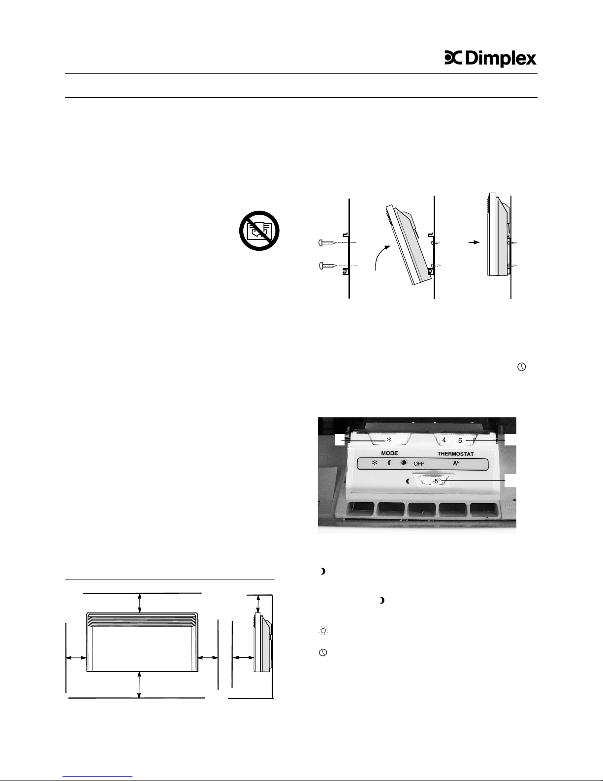
Die Montage unter einer Wandsteckdose ist verboten.
Die Mindestabstände A, B und C, insbesondere zu leicht
brennbaren Gegenständen, wie Vorhänge, Polstermöbel
usw. dürfen nicht unterschritten werden. Bitte achten Sie
darauf, daß die Luft am Gerät ungehindert ein- und
austreten kann.
Mindestabstände A B C
mm 100 100 150
Die Geräte werden nicht direkt an die Wand geschraubt,
sondern in ein Wandgestell eingehängt.
- Befestigungslöcher für Wandhalter bohren.
- Wandhalter fest an die Wand schrauben.
- Heizgerät mit den an der Geräterückwand befindlichen
Schlitzen in die Wandhalterung einhängen.
- Heizgerät hochklappen und oben am Wandhalter
befestigen.
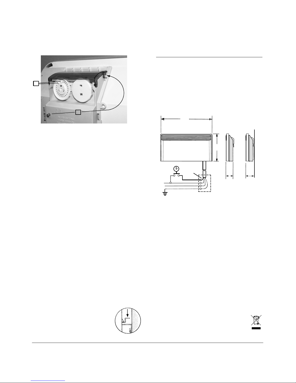
3. Elektrischer Anschluss
Zusätzlich zu den Leitungen für den Netzanschluß (L1=
braun, N= blau, PE= grün/gelb) ist eine markierte
Steuerleitung (schwarz) für externe Temperaturabsenkung
vorgesehen, z. B. über externe Zeitschaltuhr oder
Pilotgerät. Der Betriebsartenschalter muß hierzu auf „
“
(Automatischer Betrieb) gestellt werden.
Schaltbild siehe Abschnitt 8.
4. Heizbetrieb
Funktionen Betriebsartenschalter (1):
OFF = Aus
∗ = Frostschutz: Gerät schaltet bei etwa 7° C ein.
= Absenkbetrieb: Temperaturabsenkung, z.B.
während der Nacht. Die Höhe der Absenkung
gegenüber der eingestellten Temperatur kann über
Einsteller „
“ (2) gewählt werden (Beispiel:
Temperaturabsenkung von 20° C auf 17° C: „-3“
einstellen).
= Normalbetrieb, Regelung der Raumtemperatur auf
den am Temperaturregler (3) eingestellten Wert.
= Automatische Temperaturabsenkung. Wird einge-
stellt wenn eine zentrale Temperaturabsenkung,
z.B. über Schaltuhr oder Pilotgerät, vorgesehen ist.
Das Heizgerät ist mit einem Temperaturregler (3) ausgestattet,
mit dem die Raumtemperatur durch Wahl der entsprechenden
Einstellung geregelt werden kann. Die Einstellung ∗ bedeutet
eine Raumtemperatur von ca.7°C (Frostschutzstellung). Eine
Raumtemperatur von ca. 21° C entspricht dem Einstellwert 6.
B
A
500
B
A
Min.
C
D
1 3
2
Page 2
2
4a. Temperaturbereich begrenzen
Der Einstellbereich des Thermostatrades kann mit Hilfe
der beiden Stifte (1) an der Geräterückseite festgelegt
werden. Je ein Stift ist für die Begrenzung des oberen bzw.
unteren Wertes vorgesehen.
Die Stifte können durch hin- und herbewegen herausgelöst
werden.
4b. Bedienelemente sichern
Die Klappe kann mit einer Schraube gesichert werden
damit die Bedienelemente nicht unbefugt verstellt werden
können. Schraube (2) an der Rückseite des Bedienfeldes
herauslösen und wie im Bild gezeigt festschrauben.
5. Überhitzungsschutz
Zu Ihrer Sicherheit ist das Heizgerät mit einem
Überhitzungsschutz ausgerüstet. Wird die Wärmeabgabe
gestört (z.B. durch Verhängen oder Zustellen des
Luftgitters), so schaltet das Gerät automatisch ab.
Vor Wiederinbetriebnahme des Gerätes beseitigen Sie die
Ursachen für das Ansprechen des Überhitzungsschutzes.
Gleichzeitig muß die Stromversorgung des Heizgerätes für
einige Minuten unterbrochen werden
(Betriebsartenschalter auf „OFF“-Stellung).
Ist das Gerät ausreichend abgekühlt, kann es wieder in
Betrieb genommen werden. Damit die volle Heizleistung
abgegeben wird, ist es notwendig die Luftein- und
Luftaustrittsöffnungen staubfrei zu halten. Bitte vor der
Heizperiode mit Staubsauger reinigen!
6. Störungen
Wenn das Heizgerät keine Wärme abgibt, prüfen Sie bitte,
ob der Betriebsartenschalter richtig eingestellt ist (siehe
Abschnitt 4) und der Thermostat auf die gewünschte
Temperatur eingestellt ist, sodann ob der Automat in der
Stromverteilung eingeschaltet bzw. die Sicherung in
Ordnung ist. Bei Störungen wenden Sie sich bitte an Ihre
Elektrofachwerkstatt oder an die nächstgelegene
Kundendienststelle für Dimplex-Geräte.
Für die Auftragsbearbeitung werden die E-Nummer und
FD-Zahl des Gerätes benötigt. Diese Angaben finden Sie
auf dem Typschild.
7. Reinigen der Geräte
Das Gerät muß vor dem Reinigen ausgeschaltet und
abgekühlt sein. Zum Reinigen kann das Heizgerät einfach
von der Wand geklappt werden: Verschluß lösen und
Oberkante nach vorn ziehen.
Die Außenseite kann durch Abwischen mit
einem weichen, feuchten Lappen gereinigt
und dann getrocknet werden. Zur
Reinigung keine Scheuerpulver oder
Möbelpolituren verwenden, da diese die
Oberfläche beschädigen können.
8. Technische Daten, Abmessungen, Gewichte
Anschlussspannung 1/N/PE~ 230V, 50Hz
Temperaturregler 7-29°C
Schutzklasse I Schutzleiteranschluss
Schutzart IP 21 Tropfwassergeschützt
Leistung Typ Gewicht Maße in mm
W kg A B
500 KSE 050 3,4 300 430
750 KSE 075 3,6 340 430
1000 KSE 100 4,2 420 430
1250 KSE 125 4,7 500 430
1500 KSE 150 5,5 580 430
1750 KSE 175 6,0 660 430
2000 KSE 200 6,6 740 430
500 KLE 050 3,7 580 220
750 KLE 075 4,7 820 220
1250 KLE 125 6,9 1060 220
1500 KLE 150 7,2 1300 220
9. Kundendienst
Robert Bosch Hausgeräte GmbH Deutschland
Auftragsannahme
Tel.-Nr. +49 (0) 1801 / 22 33 55
Fax.-Nr. +49 (0) 1801 / 33 53 07
Ersatzteilbestellungen
Tel.-Nr. +49 (0) 1801 / 33 53 04
Fax.-Nr. +49 (0) 1801 / 33 53 08
Email: spareparts@bshg.com
Internet: http://www.dimplex.de
Robert Bosch Hausgeräte GmbH Österreich
Auftragsannahme
Tel.-Nr. 0810 240 260
Fax.-Nr. (01) 60575 51212
E-Mail: hausgeraete.ad@bshg.com
Ersatzteilbestellungen
Tel.-Nr. 0810 240 261
Fax.-Nr. (01) 60575 51212
E-Mail: hausgeraete.et@bshg.com
10. Garantie
Für dieses Produkt übernehmen wir 2 Jahre Garantie
gemäß unseren Garantiebedingungen.
Entsorgungshinweis
Das Gerät darf nicht im allgemeinen Hausmüll
entsorgt werden.
Glen Dimplex Deutschland GmbH Telefon +49 (0) 9221 / 709-564 Technische Änderungen vorbehalten
Am Goldenen Feld 18 Telefax +49 (0) 9221 / 709-589 www.dimplex.de
D-95326 Kulmbach E-Mail: kundendienst.hauswaerme@glendimplex.de
1
2
A
PE
N
Steuerleiter
schwarz
L1
105
83
B
Page 3

3
Operating and Installation Instructions
KSE and KLE Series Wall Convectors 453320.66.84gb 03/06/D
1. Important Information
Please read with care all of the information provided in
these instructions in a safe place for future reference. Pass
them on to any subsequent purchaser of the unit.
− The unit is suitable solely for heating the air in a closed
room.
− Only a qualified electrician should install or repair this
unit.
− In the event of a fault, disconnect the unit from the main
power supply (switch off or unscrew
fuse)
− Do not cover the unit - fire hazard!
− Caution! The unit is hot to the touch
when in operation.
− Do not allow appliance to be operated by children or
other persons not capable of safely using the device.
Children must be prevented from playing with or near
the appliance.
− The unit should be installed so that its controls are out of
reach of anyone in the bathtub or under the shower.
VDE 0100 Part 701 specifies that the unit may not be
installed in the protection zone. Keep the flap over the
controls closed.
− An isolating device must be provided in the electrical
wiring specified (for example, a miniature circuitbreaker). It must have a contact gap of at least 3 mm at
each pole.
− Substances which could lead to ignition or thermal
decomposition inside the unit (for example, carpet or
floor tile adhesives) must not be used unless you are
certain the unit has cooled down to room temperature.
2. Installation, Wiring, Minimum Clearances
The convector may only be installed in a horizontal position
(the control panel must always be at the top).
The convector must be installed in such a way that
flammable objects cannot ignite.
It is permissible to mount the convector on a wooden wall.
The convector must not be mounted directly beneath a wall
power socket.
It is essential that you observe the minimum clearances A,
B and C specified in the installation diagram, particularly as
regards clearances from easily flammable objects. Make
sure that air can flow into or out of the convector without
being obstructed.
Minimum clearances A B C
mm 100 100 150
The convector is not mounted directly on the wall but
installed in a wall frame.
- Drill the mounting holes for the wall frame.
- Screw the wall frame to the wall.
- Fit the convector in the wall frame using the slots on the
back of the unit.
- Swing the unit up and against the wall, latching it into
the top part of the wall frame.
3. Electrical Connection
In addition to the leads for the electrical power supply (L1 =
brown, N = blue, PE = green / yellow) a marked control wire
(black) is provided for external temperature reduction via an
external timer or pilot unit, for example. For this, the
operating mode switch must be set to the
‘’ symbol
(automatic mode). See Section 8 for circuit diagram.
4. Heating
Functions of the operating mode switch (1):
OFF = No function
∗ = Frost protection: The convector switches on when
the temperature falls to around 7 °C.
=Temperature reduction mode: this provides for
temperature reduction during the night, for example.
A regulator is provided ( ) (2) for setting the amount
by which the temperature is to be reduced (for
example, to reduce the temperature from 20° C to 17°
C, select ‘-3’).
=Normal operation: regulates the room temperature to
the value specified at the thermostat (3).
=Automatic temperature reduction: used when central
temperature reduction is available (for example, via a
timer or pilot unit).
B
A
500
B
A
Min.
C
GB
1
3
2
Page 4

4
The Heater is equipped with a thermostat (3) which you can
use to set the room temperature you want. The
∗ setting of the
themostat is for frost protection. Here the thermostat keeps the
room temperature at around 7°C. A room temperature of about
21 °C corresponds to a ‘6’ setting on the thermostat knob.
4a. Restricting the Temperature Range
With the aid of the two pins (1) on the back of the unit you
can set the range of the thermostat wheel. One pin
determines the upper value and the other pin the lower
value. Move the pins back and forth to loosen them.
4b. Locking the Controls
You can lock the controls flap to prevent unauthorized
tampering with the controls.
Undo the screw (2) at the back of the control panel and
screw it in at the position shown in the diagram above.
5. Overheating Cutout
For your protection the heater is equipped with an
overheating cutout. If the outgoing flow of air is obstructed
(for example, the air grille is covered or is closed), the
heater will cut out automatically.
Do not put the heater back into operation until you have
corrected what caused the overheating cutout to trip. You
should also switch off the power supply to the unit for a few
minutes (mode switch to OFF).
Once the unit has cooled down enough you can switch it
back on.
For you to enjoy the full power of the heater the air intakes
and outlets must be kept free of dust. Clean the heat with
your vacuum cleaner before the cold season of the year.
6. Faults
If no heat is coming out of the convector make sure that the
mode switch is set correctly (see Section 4) and that the
thermostate is set to the temperature you want. Check that
the circuit-breaker has not tripped or that the fuse has not
blown. In the event of malfunctions in your heater, please
contact your local electrician or the nearest customer
service point for Dimplex appliances. The E number and the
FD code are required before servicing can be carried out.
You will find them on the rating plate.
7. Cleaning
Before attempting any cleaning operation,
switch off the heater and wait until it has
fully cooled down. The heater can be
swung away from the wall to allow access
for cleaning: Undo the fastening and pull
the top of the heater forwards. Use a soft
damp cloth to wipe off the outside
surfaces of the heater. Do not use abrasives or furniture
polishes for cleaning as these can damage the surfaces of
the heater.
8. Technical Data, Dimensions, Weights
Supply voltage 1/N/PE~ 230V, 50Hz
Thermostat 7-29°C
Protection class l With protective earth terminal
Degree of protection IP 21 Dripproof
Rating Model Weight Dimensions in mm
W kg A B
500 KSE 050 3,4 300 430
750 KSE 075 3,6 340 430
1000 KSE 100 4,2 420 430
1250 KSE 125 4,7 500 430
1500 KSE 150 5,5 580 430
1750 KSE 175 6,0 660 430
2000 KSE 200 6,6 740 430
500 KLE 050 3,7 580 220
750 KLE 075 4,7 820 220
1250 KLE 125 6,9 1060 220
1500 KLE 150 7,2 1300 220
9. Warranty
Authorised dealers can provide information on the terms
and conditions of warranty. The warranty is not valid without
a sales receipt marked with the date of purchase.
Disposal Notice
The product should not be disposed of with your
other household waste.
1
2
Glen Dimplex Deutschland GmbH Telefon +49 (0) 9221 / 709-564 Subject to change
Am Goldenen Feld 18 Telefax +49 (0) 9221 / 709-589 www.dimplex.de
D-95326 Kulmbach E-Mail: kundendienst.hauswaerme@glendimplex.de
Germany
A
PE
N
Control wire
black
L1
105
83
B
 Loading...