

Dimplex KBE 50, KBE 75, KBE 100, KBE 125, KBE 175 Operating And Installation Instructions
...Page 1
1
Operating and Installation Instructions
KBE Wall Convectors 453321.66.85gb 07/04/A
1. Important Information
Please read with care all of the information provided in
these instructions in a safe place for future reference. Pass
them on to any subsequent purchaser of the unit.
− The unit is suitable solely for heating the air in a closed
room.
− Only a qualified electrician should install or repair this
unit.
− In the event of a fault, disconnect the unit from the
main power supply (switch off or unscrew fuse)
− Do not cover the unit - fire hazard!
− Caution! The unit is hot to the touch when in operation.
− Do not operate the unit unattended if there are small
children in the vicinity.
− Do not insert objects of any kind through the apertures
in the unit.
− The unit should be installed so that its controls are out
of reach of anyone in the bathtub or under the shower.
VDE 0100 Part 701 specifies that the unit may not be
installed in the protection zone. Keep the flap over the
controls closed.
− An isolating device must be provided in the electrical
wiring specified (for example, a miniature circuitbreaker). It must have a contact gap of at least 3 mm
at each pole.
− Substances which could lead to ignition or thermal
decomposition inside the unit (for example, carpet or
floor tile adhesives) must not be used unless you are
certain the unit has cooled down to room temperature.
2. Installation, Wiring, Minimum Clearances
The convector may only be installed in a horizontal
position (the control panel must always be at the top).
The convector must be installed in such a way that
flammable objects cannot ignite.
It is permissible to mount the convector on a wooden wall.
The convector must not be mounted directly beneath a
wall power socket.
It is essential that you observe the minimum clearances A,
B and C specified in the installation diagram, particularly
as regards clearances from easily flammable objects.
Make sure that air can flow into or out of the convector
without being obstructed.
Minimum clearances A B C
mm 150 150 150
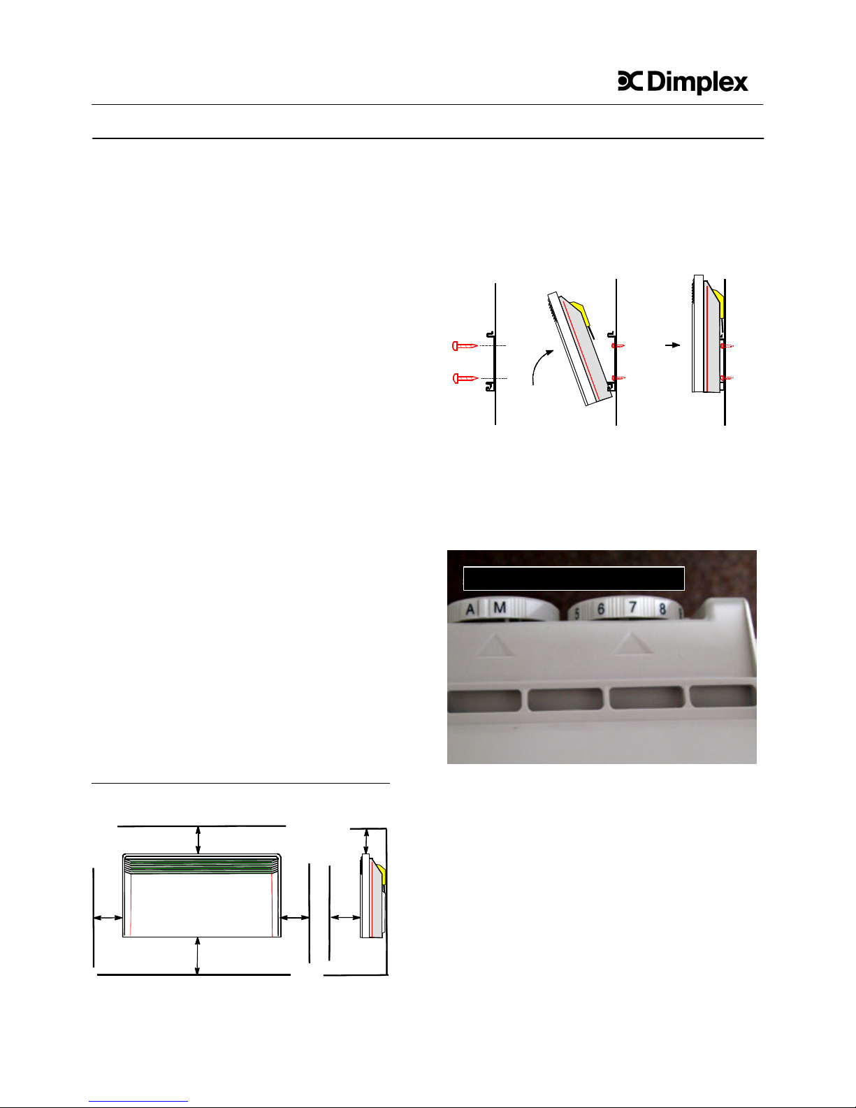
The convector is not mounted directly on the wall but
installed in a wall frame.
- Drill the mounting holes for the wall frame.
- Screw the wall frame to the wall.
- Fit the convector in the wall frame using the slots on
the back of the unit.
- Swing the unit up and against the wall, latching it into
the top part of the wall frame.
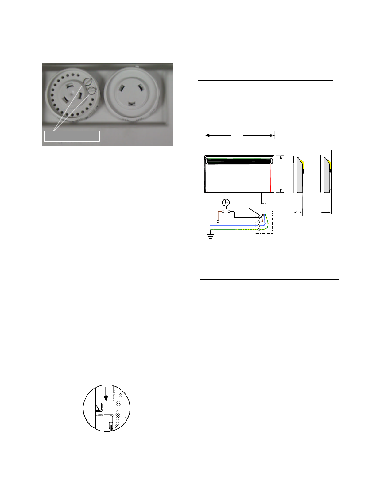
3. Electrical Connection
In addition to the leads for the electrical power supply (L1
= brown, N = blue, PE = green / yellow) a marked control
wire (black) is provided for external temperature reduction
via an external timer or pilot unit, for example.
See section 8 for circuit diagram.
4. Heating
Switch On/Off
A = Off, no function.
M = On. Thermostat regulates the room temperature to the
value specified at the thermostat knob.
Thermostat
The Heater is equipped with a thermostat which you can use
to set the room temperature you want. The ∗ setting of the
thermostat is for frost protection. Here the thermostat keeps
the room temperature at around 7°C. A room temperature of
about 21 °C corresponds to a ‘6’ setting on the thermostat
knob.
BA500BA
Min.
C
GB
Switch On/Off Thermostat
Page 2
2
4a. Restricting the Temperature Range
With the aid of the two pins on the back of the unit you
can set the range of the thermostat wheel. One pin
determines the upper value and the other pin the lower
value.
Move the pins back and forth to loosen them.
5. Overheating Cut-out
For your protection the heater is equipped with an
overheating cut-out. If the outgoing flow of air is
obstructed (for example, the air grille is covered or is
closed), the heater will cut out automatically.
Do not put the heater back into operation until you have
corrected what caused the overheating cut-out to trip. You
should also switch off the power supply to the unit for a
few minutes (mode switch to OFF).
Once the unit has cooled down enough you can switch it
back on.
For you to enjoy the full power of the heater the air intakes
and outlets must be kept free of dust. Clean the heat with
your vacuum cleaner before the cold season of the year.
6. Faults
If no heat is coming out of the convector make sure that
the On/Off switch is set to position "M" (see Section 4) and
that the thermostat is set to the temperature you want.
Check that the circuit-breaker has not tripped or that the
fuse has not blown.
In the event of malfunctions in your heater, please contact
your local electrician or the nearest customer service point
for Dimplex appliances. The E number and the FD code
are required before servicing can be carried out. You will
find them on the rating plate.
Any examination of the heater or repair work may only be
carried out by a qualified electrician or after-sales service
technician.
7. Cleaning
Before attempting any cleaning operation, switch off the
heater and wait until it has fully cooled down. The heater
can be swung away from the wall to allow access for
cleaning: Undo the fastening and pull the top of the heater
forwards.
Use a soft damp cloth to wipe off the outside surfaces of
the heater. Do not use abrasives or furniture polishes for
cleaning as these can damage the surfaces of the heater.
8. Technical Data, Dimensions, Weights
Supply voltage 1/N/PE~ 230V, 50Hz
Thermostat 7-29°C
Protection class l With protective earth
terminal
Degree of protection IP 21 Drip proof
Rating Model Weight Dimensions in mm
W kg A B
500 KBE 50 3,4 360 400
750 KBE 75 3,7 360 400
1000 KBE 100 4,3 440 400
1250 KBE 125 4,9 520 400
1500 KBE 150 5,5 600 400
1750 KBE 175 6,0 760 400
2000 KBE 200 6,6 840 400
9. Warranty
Authorized dealers can provide information on the terms
and conditions of warranty. The warranty is not valid
without a sales receipt marked with the date of purchase.
KKW Kulmbacher Klimagerätewerk GmbH
Geschäftsbereich Dimplex Tel. +49 (0) 9221 / 709-564
Am Goldenen Feld 18 Fax +49 (0) 9221 / 709-565
D-95326 Kulmbach www.dimplex.de
Kundendienst@dimplex.de
A
PE
N
Control wire
black
L1
105
83
B
Restriction pins
 Loading...