

Page 1
Free-E User Manual
Heat water for free with solar PV.
8/60510/0 Version A
Page 2

Millbrook House, Grange Drive, Hedge End, Southampton SO30 2DF
0844 879 3587
dimplex.co.uk | gdcgroup.co.uk
Dimplex
R
Page 3

Millbrook House, Grange Drive, Hedge End, Southampton SO30 2DF
0844 879 3587
dimplex.co.uk | gdcgroup.co.uk
Dimplex
R
Manual Contents
1 Manual Information 1
2 Safety Information 2
3 Free-E Overview - How It Works 3
4 Using The Free-E Interface 5
5 Appendices 11
6 Consumer Information 16
2.1 Legionella Warning 2
3.1 Key Features 4
5.1 Appendix 1 - Technical Specifications for Energy Meter 12
5.2 Appendix 2 - Technical Specifications for Free-E 13
5.3 Appendix 3 - WiFi Connection Information 14
2.2 General Safety Guidelines 2
2.3 General Maintenance Guidelines 2
2.4 Electrical Safety Guidelines 2
2.5 Legal
2.6 Intended Use
2
2
4.2 Settings Menu 6
4.2.1 Boost Options 6
4.2.2 Disable Free-E 8
4.2.3 Set Date / Time 8
4.2.4 Light OFF Interval 8
4.3 Advanced Settings 9
4.3.1 Factory Reset 9
4.3.2 Load Diversion 9
4.3.3 WiFi Connection 9
4.3.5 RF Channel Selection 10
4.3.4 General Info 9
4.3.6 Update Firmware 10
4.1 Main User Interface Screen and Colours 6
4.1.1 Backlight Colour Indicators 6
4.1.2 Main Menu 6
Page 4
THIS MANUAL REFERS TO THE FOLLOWING PRODUCTS;
Free-E Meter (certified as part number: 054722)
Free-E (certified as part number: 054739)
Please retain this manual for future reference.
1 Manual Information
Electrical Warnings
Indicates any hazard of an electrical nature.
General Warnings
Indicates a general warning against actions which could result in damage to the system or
personal injury to the installer and/or user.
Warnings and Icons Used
Information
Indicates tips and advice for the smooth operation of the system
!
!
!
Millbrook House, Grange Drive, Hedge End, Southampton SO30 2DF
0844 879 3587
dimplex.co.uk | gdcgroup.co.uk
1
Dimplex
R
Page 5

2 Safety Information
2.1 Legionella Warning
Legionella bacteria can be found in natural water sources in low concentrations. At this level it will not pose a
risk to human health, however the nature of domestic hot water storage tanks or boilers may allow the bacteria
to reproduce if the water is left stagnant for a long time.
Under normal circumstances, the frequent use of the hot water tank will protect against the growth of bacteria,
however if the tank will be left unused for a prolonged period, for example, if you are going on holiday, it is highly
recommended to ensure that any boiler controls are set to heat the water to 60°C+ at least once per week to
protect against Legionella.
2.2 General Safety Guidelines
This appliance is not intended for use by persons (including children) with reduced physical, sensory or mental
capabilities, or lack of experience and knowledge, unless they have been given supervision or instruction regarding
the use of the appliance by a person responsible for their safety. Children should be supervised to ensure that they
do not play with the appliance.
The Free-E has a software generated alarm which prevents it from running when an error has occurred.
2.3 General Maintenance Guidelines
Regular maintenance of the Free-E ensures a long operating life and optimal efficiency.
The Free-E fan and ventilation grids should be cleaned periodically using a vacuum cleaner.
The following procedure should be followed;
- Disconnect the Free-e on the AC side
- Wait 5 minutes until the residual voltage has been drained and the fan is no longer turning
- Gently clean the top and bottom ventilation grids with a vacuum cleaner
Never use cleaning agents containing sand, soda, acid or chloride, as these can damage the casing of the Free-e.
The display screen should be wiped clean with a soft, dry cloth.
2.4 Electrical Safety Guidelines
When using electrical devices, there is always a risk of fire or explosion. To prevent this from occurring please
ensure that;
- The Free-E system is not placed close to any flammable materials
- The Free-E system is not placed in any areas with potential for explosion.
2.5 Legal
The construction and design of the Free-E complies with all relevant EU directives.
2.6 Intended Use
This product is designed to redistribute energy generated by a PV system to an immersion heater, that would
otherwise have been exported to the grid, and is intended for domestic and light commercial use only. Any other
use beyond that intended by the manufacturer is prohibited. This requires the user to abide by the manufacturer's
product information. Please refrain from tampering with or altering the device.
Millbrook House, Grange Drive, Hedge End, Southampton SO30 2DF
0844 879 3587
dimplex.co.uk | gdcgroup.co.uk
2
Dimplex
R
Page 6
Millbrook House, Grange Drive, Hedge End, Southampton SO30 2DF
0844 879 3587
dimplex.co.uk | gdcgroup.co.uk
3
Dimplex
R
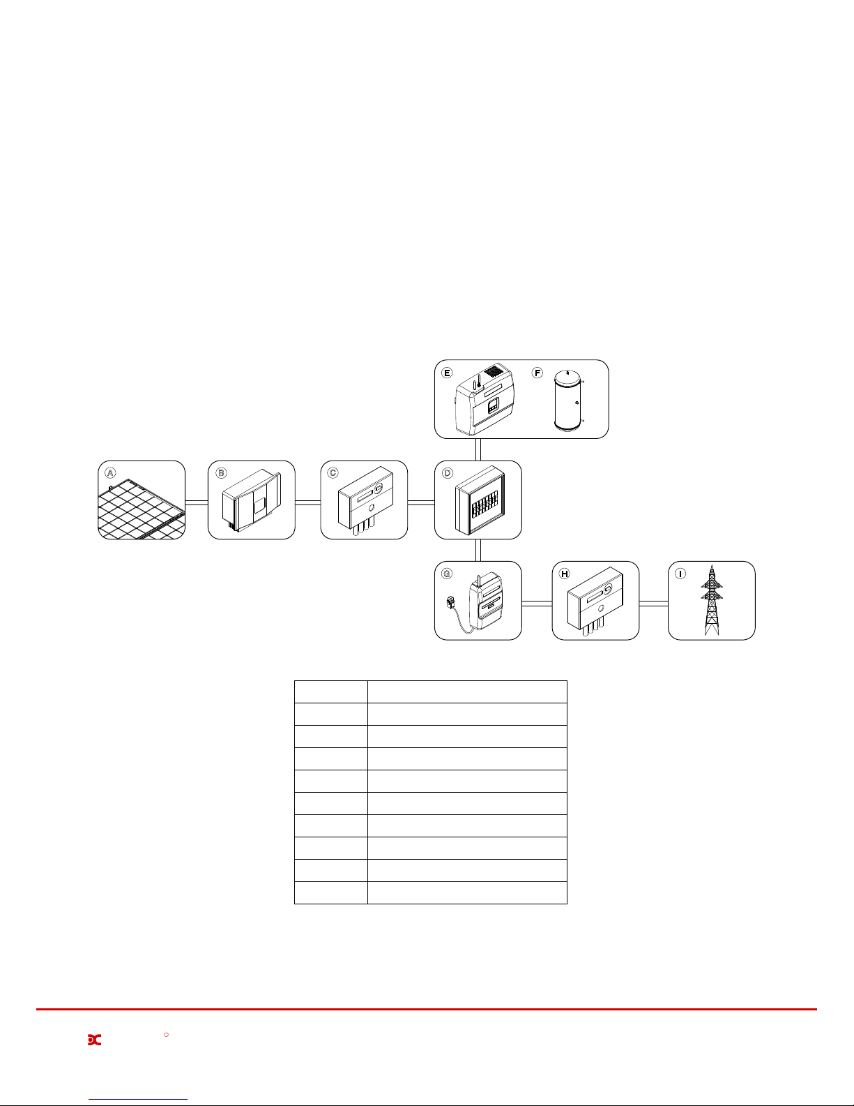
3 Free-E Overview - How it Works
When PV panels generate electricity, the production is initially consumed by electrical appliances or devices
in the household that are creating a demand for energy. If the household does not consume all of the energy
produced by the PV panels, the surplus energy will be sent to the grid.
The Free-E uses this surplus photovoltaic energy instead to heat the water in a household water tank, and
therefore prevent this energy from going to waste. The Free-E can divert up to 95% of unused (otherwise
exported) solar PV electricity to an electrical water heating device. This maximises the consumption of selfgenerated solar power and minimises the cost of buying energy for domestic hot water. It can be retrospectively
fitted to homes already with solar PV and a hot water cylinder.
A
B
C
D
E F
G H I
Grid
PV Panels
Description
B
Domestic Hot Water Cylinder
Distribution Box
PV Solar Electricity Meter
Import / Export Electricity Meter
A
Inverter
H
E
Free-E Meter and CT Clamp(s)
I
Free-E
F
Position
C
G
D
Page 7

Millbrook House, Grange Drive, Hedge End, Southampton SO30 2DF
0844 879 3587
dimplex.co.uk | gdcgroup.co.uk
4
Dimplex
R
3.1 Key Features
- Uses excess energy produced by your PV system to heat water
- Monitors and adjusts the power imported and exported to the grid, ensuring that the exported power remains at
virtually zero when the PV system is producing enough energy to cover the demand for domestic electricity and hot
water
- Timed boost function available, which can be set for multiple days of the week
- Back-lit LCD display with different Light OFF times available, which displays information about the operating mode,
settings, Wi-Fi connection and more
- The current imported, exported and diverted power level can be viewed.
- Compatible with most existing immersion heaters and underfloor heating systems
-Internal software alarm system, thermal protection, overload protection and soft start option - all of which prevent
damage to the system and give you peace of mind
- Approved CE product
- 3 Year Warranty
- The load diversion adjusted from 0-100%
Page 8

4 Using The Free-E Interface
The Free-E interface is controlled using the three buttons located below the screen, as shown below;
ENTER
Export
Store
0.05kW
0.05kW
02/02/2015
08:23
Power being exported
Power being stored
Cloud upload status,
RF communications
and WiFi connection
icons
Back / Esc Button
Navigation Button
Enter / Confirm Button
Wi-Fi Connection
This symbol indicates that theWi-Fi is connected and operating correctly. If this symbol is not
displayed, please check your Wi-Fi connection.
Uploading to Cloud Storage
This symbol is not displayed permanently, but will flash every few minutes as data is uploaded to
the Dimplex cloud.
RF Communication
Displays when the Free-E meter is communicating with the master module.
Downloading Updates
This symbol is not displayed permanently, but will flash while a software update is being downloaded.
Millbrook House, Grange Drive, Hedge End, Southampton SO30 2DF
0844 879 3587
dimplex.co.uk | gdcgroup.co.uk
5
Dimplex
R
R
The enter button is used to access the advanced settings menu from the main menu. It is also the confirmation
button for selections made on the user interface. The left / back button is used to escape from menus or
selections.
All navigation up / down through the menus on the user interface will be carried out by using the right button.
This button allows scrolling down through the displayed options, and when the end of the menu is reached,
continuing to press the down / next button will return the user to the top of the menu.
The screen shown above in is the default screen saver on the Free-E user interface. It displays the current store
power being diverted in watts, the current power being imported or exported, the current date and time, and icons
for the connectivity status, which are;
Date and Time
Page 9

4.1 Main User Interface Screen and Colours
4.2 Settings Menu
4.1.1 Backlight Colour Indications
If the Free-E is exporting energy and storing power, the backlight will be green. If no energy is being exported or
energy is being imported from the grid, the backlight will be blue. If there is a fault or error with the operation of the
Free-E, the backlight will be red.
4.1.2 Main Menu
To access the main user menu, simply press the enter button when on the default screen saver as shown below.
From the main menu, you will have access to the settings and advanced settings menus.
02/02/2015
08:35
Export
Import
0.00kW
0.00kW
ENTER
Press Enter Button
MAIN MENU
ADVANCED SETTINGS
SETTINGS
The settings menu allows access to boost set-up options, disabling the Free-E device, date and and time settings
and light off interval settings.
SETTINGS
Boost Options
Disable Free-E
Set Date / Time
Light Off Interval
4.2.1 Boost Options
The Free-E provides options for both a manual (ON/OFF) one-hour default boost, or for a timed boost, which can be
set for three different timer periods, up to 7 days a week.
Manual Boost
To activate the manual boost, simply select Boost Options, then Manual Boost. You will see the confirmation screen
as shown below when the manual boost is activated, and the default display screen on the screen will display the
Manual Boost message shown below.
Manual Boost
Timed Boost
Boost Options
ENTER
Press Enter Button
Millbrook House, Grange Drive, Hedge End, Southampton SO30 2DF
0844 879 3587
dimplex.co.uk | gdcgroup.co.uk
6
Dimplex
R
Boost function ON
Manual Boost
OK
02/02/2015
08:35
MANUAL BOOST
Page 10

The manual boost is automatically set to run for a duration of one hour, however you can also deactivate it
manually by returning to the Boost Options and selecting Manual Boost while the boost is still active. You will
see a confirmation screen as shown below and the manual boost message will no longer appear on the default
main screen.
Timed Boost
The Timed Boost can be set for a specified time for multiple weekdays. The timer should be set first using the
Timer Settings menu, then the Set Weekdays menu allows you to select which of the three programmable boost
timers will be activated for each weekday. You can set any combination of the three timers, for any or all weekdays.
Each timer must be assigned an ON time when set up, but you can also select the duration of the boost. The options
for boost duration ranges from 30 minutes to 2 hours.
The Set Weekdays menu will let you scroll across between the days Sunday - Saturday (SU - SA), and on selecting
each day, you will be brought to the menu for that day which will show a list of tick boxes for each timer that you can
enable.
Timer 1 - Duration
0.5h
1.0h
1.5h
2.0h
Set weekdays
SU MO TU WE TH FR SA
ENTER
Press Enter Button
ENTER
Press Enter Button
ON Time
Duration
Timer 1
ON Time
Duration
Timer 1
Millbrook House, Grange Drive, Hedge End, Southampton SO30 2DF
0844 879 3587
dimplex.co.uk | gdcgroup.co.uk
7
Dimplex
R
Manual Boost
Timed Boost
Boost Options
Timer Settings
Set Weekdays
Timed Boost
ENTER
Press Enter Button
Timer 1
Timer 2
Timer 3
Timer Settings
ENTER
Press Enter Button
Manual Boost
Timed Boost
Boost Options
ENTER
Press Enter Button
Boost function OFF
Manual Boost
OK
CANCEL
Timer 1 - ON Time
SAVE
00:00
Set weekdays - SU
for timer(s):
Timer 1
Timer 2
Timer 3
ABORT
SAVE
Quick Steps for Using Manual Boost
Turning ON or OFF the manual boost can be carried out simply by pressing the Enter button 4 times.
!
Page 11

4.2.2 Disable Free-E
4.2.3 Set Date / Time
4.2.4 Light OFF Interval
This option allows you to set the current date and time for the Free-E user interface. This function is important
for the smooth operation of the boost timers and other data. Please ensure that the current date and time are set
correctly.
This option allows you to set the OFF time for the backlight of the Free-E user interface when not in use. The light
OFF interval can be set to 1 minute, 30 minutes or never, which will prevent the backlight from turning off. The
default setting is 30 seconds.
This option allows you to temporarily disable the Free-E. If, for any reason, the Free-E needs to be turned off, do
not disconnect the system from the mains supply.
The Disable Free-E function is provided for this purpose, and is useful, for example, if you are going on holiday
and would like to turn off the system while you are away.
Selecting Disable Free-E ON will disable the system, and a message will appear on the main screen saver to
indicate that the Free-E is on standby (see image above). During this time, the Free-E will not perform functions,
however you will still have full access to all menus.
Millbrook House, Grange Drive, Hedge End, Southampton SO30 2DF
0844 879 3587
dimplex.co.uk | gdcgroup.co.uk
8
Dimplex
R
ON
OFF
Disable Free-E
ENTER
Press Enter Button
CANCEL
Set Date / Time
SAVE
00:00
01/01/2015
Free-E Disabled
System on Standby
Disable Free-E
OK
ON
OFF
Disable Free-E
ENTER
Press Enter Button
Free-E Enabled
Normal Operation
Disable Free-E
OK
02/02/2015
08:35
ON STANDBY
1 minute
30 seconds
Light off
30 minutes
Never
Light OFF Interval
Page 12

4.3 Advanced Settings
4.3.3 WiFi Connection
4.3.4 General Info
The factory reset function shoul only be used if strictly necessary. and should NEVER be carried out by anyone
without knowledge of how to re-commission the system correctly. It is not possible to use the system without
commissioning, and all commissioning settings will be cleared by a factory reset.
For information on connecting the Free-E to a WiFi network, see appendix 3.
The General Info option allows you to access and view information such as the software version (Version), the
device’s serial number (Serial n*), the input voltage (Input V), the grid current (Grid I), the supply frequency
(Frequency), the device current being measured (Current) and the output in watts (Output).
4.3.1 Factory Reset
Millbrook House, Grange Drive, Hedge End, Southampton SO30 2DF
0844 879 3587
dimplex.co.uk | gdcgroup.co.uk
9
Dimplex
R
WiFi Connection
General Info
RF Channel Selection
Update Firmware
Factory Reset
Load Diversion
ADVANCED SETTINGS
Input V: 0.0V
Serial n*: 1015220002
Version: 0.1
Grid I: 4.49A
Frequency: 0.5Hz
Current: 0.00A
Output: 0W 0%
General Info
ENTER
Press Enter Button
Are you sure you want to
reset the system?
WARNING:
This change is permanent
Factory Reset
ABORT
OK
Factory Reset in Progress
Do not disconnect the system
Please Wait
DO NOT FACTORY RESET THE FREE-E UNLESS YOU ARE QUALIFIED TO RE-COMMISSION IT!
Factory resetting the Free-E will remove all configurations and will not allow any functions to be carried
out until the commissioning procedure is complete.
!
4.3.2 Load Diversion
The Load Diversion function is a test/diagnostic function which allows the Free-E unit to be driven to a particular
output state, independent of the Free-E Meter readings.
This option allows the unit to be driven ON between 0 and 100 % (if a 3kW load is connected at the output this will
be 0 to 3kW) in roughly 1% steps.
This is not a user function. It is useful for fault finding as the Free-E variable output, L1 ,can be driven ON even
though there is no nett export power being measured by the Free-E Meter.
Page 13

Millbrook House, Grange Drive, Hedge End, Southampton SO30 2DF
0844 879 3587
dimplex.co.uk | gdcgroup.co.uk
10
Dimplex
R
4.3.5 RF Channel Selection
The default RF channel is Channel 1 and will generally not need to be changed. If you experience interference,
however, you can change this channel between channels 1-4 until the reception is clearer.
4.3.6 Updating Firmware
You can check for firmware updates by selecting the Update Firmware option in the Advanced Settings menu.
Once this option is selected, the software will check for updates automatically. If a new firmware update is
available, the screen display will confirm this and the firmware update will begin automatically.
Channel 2
Channel 3
Channel 4
Channel 1
RF Channel Selection
Update Firmware
Ste p:9
Ver sion: 5
Che cksum : 136 65325
Fil e siz e: 17 6556
Dow nload ing F irmwa re:
634 88/17 6556
Page 14

Millbrook House, Grange Drive, Hedge End, Southampton SO30 2DF
0844 879 3587
dimplex.co.uk | gdcgroup.co.uk
11
Dimplex
R
5 Appendices
5.1 Free-E Meter Technical Specifications
5.2 Free-E Technical Specifications
5.3 WiFi Connection Information
List of Appendices
Page 15

Millbrook House, Grange Drive, Hedge End, Southampton SO30 2DF
0844 879 3587
dimplex.co.uk | gdcgroup.co.uk
12
Dimplex
R
5.1 Appendix 1 - Technical Specifications - Energy Meter
Ordering Codes
DOEE 054722
Voltage / Current
Input Voltage Range 100V to 255V AC, 50/60Hz
Voltage Accuracy +/- 1%
Voltage Resolution 0.1 Volt
Current Measurement Range 0.1 to 80A
Current Accuracy %1-/+ A08 ~A4 %5.1-/+ A4~A6.1
Current Resolution 0.01A
kWh, PF, kVAh kWh Accuracy +/- 1%
kWh Resolution 0.01 kWh
Power Factor Accuracy +/- 1%
Power Factor Resolution 0.01
kVAh Accuracy +/- 1%
kVAh Resolution 0.01 kVAh
Certification
Certification CE
Metering Standard Class 1 (Accuracy only)
Wireless Technology
Radio Technology Dimplex GFSK
Radio Frequency 868 MHz ISM Band
Channels 4 Channels (1 - 4)
Max Tx Power +13dBm
Rx Sensitivity -105dBm@25Kbps
Data Rate up to 25 kbits/sec
Wireless Range Indoor Range up to 50m
Outdoor Range up to 300m (direct line of sight)
Rated input power
Power Consumption 1 Watt
Physical
Dimensions (LxWxH) 231 x 125 x 48 mm
Weight 0.201 kg
Mounting Wall Mounting Flanges
Enclosure V0 Polycarbonate
Operating Temperature -20°C to +45°C
Operating Humidity up to 85% (non-condensing)
Page 16

Millbrook House, Grange Drive, Hedge End, Southampton SO30 2DF
0844 879 3587
dimplex.co.uk | gdcgroup.co.uk
13
Dimplex
R
5.2 Appendix 2 - Technical Specifications - Free-E
Ordering Codes
DOMM 054739
Voltage / Current
Input Voltage Range 215V to 255Vac, 50/60Hz
Maximum continuous AC output current at 210 V 14.2A +/-1%
Maximum continuous AC output current at 230 V 13.0A +/-1%
Maximum continuous AC output current at 254 V 11.8A +/-1%
16A +/-1%
Maximum output over current protection
Maximum input overvoltage protection 260 Vac
Cooling conceptElectrical Forced Air Convection
Relay output ratings
16A…... 250Vac
0.9x … 1.0
Range of output power factor
0.99
Nominal Power factor
24 - 230Vac
External Input voltage range
98.2%
Wireless Technology
Radio Technology Dimplex GFSK
Radio Frequency 868 MHz ISM Band
Channels 4 Channels (1-4)
Max Tx Power +13dBm
Rx Sensitivity -105dBm@25Kbps
WiFi IEEE 802.11 b/g/n
Wireless Range Indoor Range up to 50m
Outdoor Range up to 300m (direct line of sight)
Standby Power
Power Consumption 10 Watt
Physical
Dimensions (LxWxH) 316 x 279 x 110 mm
Certifications
CE Fully EMC Compliant
Weight 3.7kg
Mounting Wall Mounting Flanges
Enclosure V0 Polycarbonate
Operating Temperature -20°C to +45°C
Operating Humidity up to 85% (non-condensing)
Peak Free-E efficiency
Page 17

Millbrook House, Grange Drive, Hedge End, Southampton SO30 2DF
0844 879 3587
dimplex.co.uk | gdcgroup.co.uk
14
Dimplex
R
5.3 Appendix 3 - WiFi Connection Information
WiFi Connection
General Info
RF Channel Selection
Update Firmware
Factory Reset
Load Diversion
ADVANCED SETTINGS WiFi Connection
Provision
Information
WiFi Provision
Please connect to:
SSID: Free-e_AP
Open browser & visit:
192.168.1.1/dimplex.html
Connecting the Free-E Device to WiFi
When you want to connect the Free-E to WiFi, you must access the WiFi provision option.
To do this, you must go to Advanced Settings on the main menu, then select WiFi Connection, then Provision.
For the next step, you will need a smartphone, tablet or laptop to access the web address
given on the Free-E screen as shown in the image above. You will need to open the WiFi
connection options/settings on your device (similar to the image shown on the left) and
connect to the Free-e network.
Next, you must open the browser on your device and visit the address given on the WiFi
Provision Free-E screen;
192.168.1.1/dimplex.html
Once you have opened the browser and entered the site address, a dialogue box will
appear which will prompt you to enter a user name and password;
User name: admin
Password: admin
After correctly inputting the login information, you should be able
to see the Client Settings page as shown on the left. Choose the
Select an Existing Network option.
Page 18

Millbrook House, Grange Drive, Hedge End, Southampton SO30 2DF
0844 879 3587
dimplex.co.uk | gdcgroup.co.uk
15
Dimplex
R
The Free-E will now scan for any existing networks available in
the area.
This may take up to 45 seconds.
When the scan is complete, a list of found networks will be displayed.
Select the network that you wish the Free-E to connect to.
When you have selected the network that you wish to connect to,
the Configure Wireless and Network Settings will be displayed.
MyHomeNetwork
MyHomeNetwork
You will be asked to input a passphrase, which by default will be your
WiFi network password.
When this is complete, click the Advanced Options box. This will display
options for obtaining or setting your IP address.
Select the Acquire IP Address Automatically (DCHP) option.
A Wireless Configuration Summary will now be displayed.
You must select the Save and Apply option to keep your network
settings.
The Free-e should now be connected to your WiFi network.
You will see a Wireless Settings confirmation screen.
To check that your Free-E has successfully connected to the WiFi
network, press the back/esc button on the device.
On returning to the main menu screen on the user interface, you should
see the WiFi icon.
Export
Store
0.05kW
0.05kW
02/02/2015
08:23
MyHomeNetwork
Page 19

Millbrook House, Grange Drive, Hedge End, Southampton SO30 2DF
0844 879 3587
dimplex.co.uk | gdcgroup.co.uk
16
Dimplex
R
6 Consumer Information
The Dimplex Free-E complies with the applicable EU directives;
EC Directives:
Low voltage directive 2006/95/EC
EMC directive 2004/108/EC
Applied Standards:
ISEN 55014-1: 2006 + A1:2009
ISEN 55014-2: 1997+ A1:2001 + A2:2008
ISEN 55022: 2010
ISEN 61000-3-2: 2006 + A1:2009 + A2:2009
ISEN 61000-3-3: 2008
ISEN 60335-1-2012
6.1 Compliance Information
6.2 After Sales Service
Your product is guaranteed for 3 years from the date of purchase. Within this period we undertake to repair or replace
this product free of charge (subject to availability) provided it has been installed and operated in accordance with these
instructions. Your rights under this guarantee are additional to your statutory rights , which in turn are not affected by this
guarantee.
Should you require 24hr sales service you should contact our customer services help desk on 0844 879 3588. It would
assist us if you can quote the model number, date of purchase and nature of fault at the time of your call. Please do not
return a faulty product to us in the first instance, as this may result in loss or damage and delay in providing you with a
satisfactory service.
Page 20

Millbrook House, Grange Drive, Hedge End, Southampton SO30 2DF
0844 879 3587
dimplex.co.uk | gdcgroup.co.uk
Dimplex
R
 Loading...