

Dimplex Firefly FIF20, Firefly FIF15, Merlin MRL20, Merlin MRL15, Alderbury ALB20 Installation And Operating Instructions Manual
Page 1
Installation and Operating Instructions
Firefly, Model FIF20 2.0 kW Fan Heater
Model FIF15 1.5 kW Fan Heater
Merlin, Model MRL20 2.0 kW Fan Heater
Model MRL15 1.5 kW Fan Heater
Alderbury, Model ALB20 2.0 kW Fan Heater
Focal Point Stove with Optiflame
{
Incor
p
orating fan heater
Issue 5 8/18299/0 25/5/01
Electrical
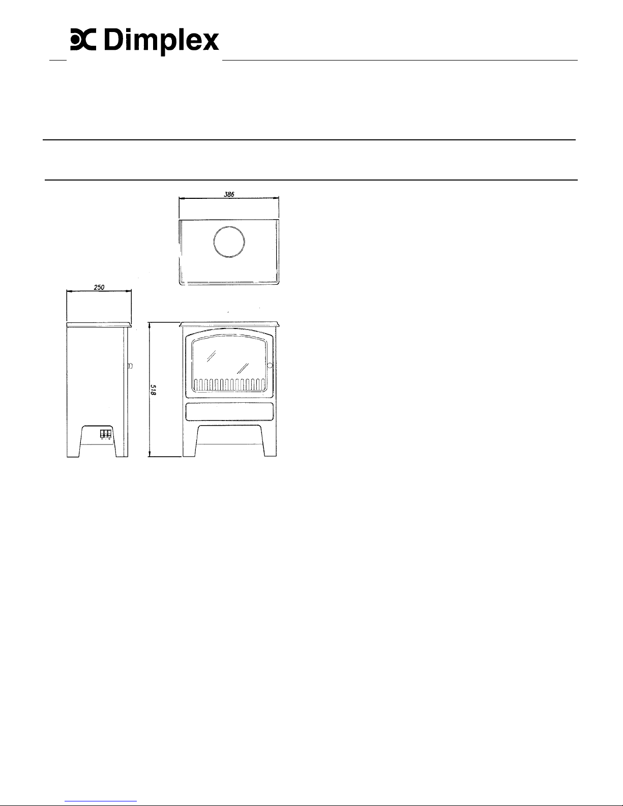
Dimensions
(millimetres)
WARNING: THIS APPLIANCE MUST BE EARTHED.
This fire is suitable for operation on an AC~ electricity
supply having the same voltage as that shown on its
rating label.
The fire is fitted with a rewireable plug incorporating a
13 amp fuse. In the event of replacing the fuse in the
plug supplied, a 13amp fuse approved by ASTA to
BS1362 must be used.
Important Safety Advice
When using electrical appliances, basic precautions
should always be followed to reduce the risk of fire,
electric shock, and injury to persons, including the
following:
• If the appliance is damaged, check immediately
with the supplier before installation and operation.
• DO NOT use outdoors.
• DO NOT use in the immediate surroundings of a
bath shower or swimming pool.
• DO NOT locate the heater immediately below a
fixed socket outlet or connection box.
Fig.1
•
•
•
• DO NOT COVER THE HEATER. Do not place
material or garments on the heater, or obstruct the
air circulation around the heater, for instance by
curtains or furniture, as this could cause
overheating and a fire risk.
IMPORTANT
DO NOT leave young children, the elderly, or the
infirm unsupervised in the vicinity of the heater.
THESE INSTRUCTIONS SHOULD BE READ
CAREFULLY
• Do not use this heater in series with a thermal
control, a program controller, a timer or any other
device that switches on the heater automatically,
since a fire risk exists when the heater is
accidentally covered or displaced.
AND RETAINED FOR FUTURE REFERENCE.
General
Unpack the heater carefully and retain the packaging
for possible future use, in the event of moving or
returning the fire to your supplier.
• Ensure that furniture, curtains or other combustible
material are positioned no closer than 1 metre
from the heater.
This model is designed to be free standing and is
normally positioned against a wall.
In the event of a fault unplug the heater.
A choice of 1kW or 2kW heat output is provided by the
fan heater, which is concealed beneath the unit.
Unplug the heater when not required for long
periods.
(Models FIF15 and MRL15, 750W or 1.5kW output).
• Keep supply cord away from the front of the
heater.
A minimum distance of 1 metre (39”) must be
maintained between the front of the heater and any
surrounding furniture, overhanging curtains or other
obstructions.
• Although this heater complies with safety
standards, we do not recommend its use on deep
pile carpets or on long hair type of rugs.
•
The appliance must be positioned so that the plug
is accessible.
Before connecting the heater check that the supply
voltage is the same as that stated on the heater.
• If the supply cord is damaged it must be replaced
by the manufacturer or service agent or a similarly
qualified person in order to avoid a hazard.
Page 2

FRONT
GLASS
REAR
GLASS
Operation
The unique flame effect may be enjoyed whether or
not the heating elements are in operation.
Controls
The heater controls are located on the left hand side of
the fan heater. (see fig 1).
Three switches provide a choice of heat settings. A
switch is in the ON position when the red indicator
mark on the switch is visible.
Switch 1 - Controls the electricity
supply to the heater
Fig.4
and the flame effect.
Note: This switch must
Replace the defective lamp with a 240V 60W B22
Fireglow 2 pin bayonet cap lamp. Fit the fuel effect and
rear glass back in position ensuring the reflectors are
not trapped. To refit top, locate and slide forward to
engage under the ledge at the front. Secure with
screws.
be in the ON position
for the heater to
operate.
Fig.2
Switch 2 - Provides 1kw heat output.
(Models FIF15 & MRL15, 750W heat output)
Safety cut- out
Switch 3 – Provides 2kw heat output with switch 2.
(Models FIF15 & MRL15, 1.5kW heat output)
An automatic cutout will switch off the heater if for any
reason it overheats. This could occur for instance, if
the air inlet or outlet were restricted in any way. The
cut-out will continue to operate until the restriction has
been removed, after which normal operation will
resume.
Maintenance
WARNING – BEFORE UNDERTAKING ANY
MAINTENANCE OR CLEANING REMOVE PLUG OR
DISCONNECT FROM THE ELECTRICITY SUPPLY.
Lamp Replacement Cleaning
For general cleaning uses a soft clean duster or, if
necessary, damp clothe – never use abrasive
cleaners.
The glass viewing screen should be cleaned carefully
with a chamois leather. DO NOT use proprietary glass
cleaners.
One lamp is located beneath the fuel effect.
To gain access to the lamp, the top cover secured by
two screws must be removed. The screws are located
at the back of the stove. (see fig.3).
After Sales Service
Your product is guaranteed for one year from the date
of purchase. We undertake to exchange or repair free
of charge within this period, any part (excluding lamps)
found to be defective due to manufacturing fault.
Should you require after sales service, please get in
touch with the supplier through whom you purchased
the appliance or your nearest Dimplex Service Agent.
Fig.3
Please do not initially return a faulty appliance or part
of an appliance to us as this may result in transit
damage and/or delay in providing service. Let us know
your difficulty quoting the model number and series
letter of the appliance. We will then take the
appropriate action.
Remove screws slide top backwards and lift clear.
Remove rear glass and fuel effect.
This appliance complies with European Safety Standard EN 60335-2-30, and European Standards EN 55014, EN 60555-2
and EN 60555-3 for Electromagnetic Compatibility. These standards cover the requirements of EEC Directives 73/23 and 89/336.
Glen Dimplex UK Limited UK customer help line (8.00AM – 6.00PM Mon-Fri; 8.30AM-1.00PM Sat)
Millbrook House
Grange Drive Customer Services: Tel. 0870 7270101
Hedge End Fax. 0870 7270102
Southampton
Hampshire Republic of Ireland 01. 8424833
SO30 2DF
 Loading...