

Page 1
Floor Drop-In Heater
FFIH15A31 Series
IMPORTANT INSTRUCTIONS
When using electrical appliances, basic precautions should
always be followed to reduce the risk of re, electric shock
and injury to person, including the following:
Read all instructions before using this heater.1.
A heater has hot and arcing or sparking parts inside. Do 2.
not use it in areas where gasoline, paint or ammable
liquids are used or stored.
This heater is hot when in use. To avoid burns, do not let 3.
bare skin touch hot surfaces. If provided, use handles
when moving this heater. Keep combustible materials
such as: furniture, pillows, bedding, papers, clothes and
curtains away from heater.
To prevent a possible re, do not block air intakes or 4.
exhaust in any manner. Do not use on soft surfaces like
a bed where openings may become blocked.
Do not insert or allow foreign objects to enter any venti-5.
lation or exhaust opening as this may cause an electric
shock or re, or damage the heater.
SAVE THESE INSTRUCTIONS
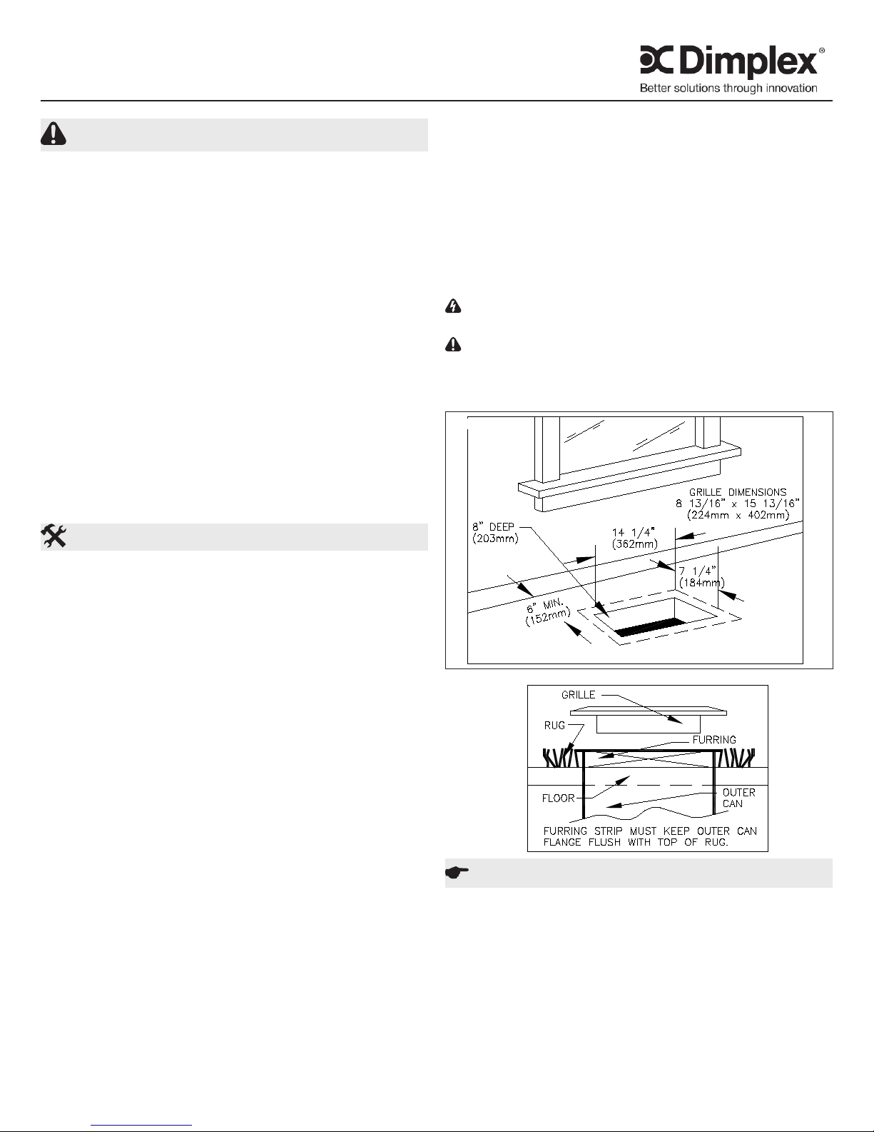
Insert outer case into oor. Flange must be located at 5.
top of nished oor or carpet. Furring strips as thick as
the pad and carpet must be used. Edge of carpet and
pad must not extend into heater. Secure outer case to
the oor with screws or nails. Pull through about 6” (153
mm) of supply wires and connect to pigtails. Connect
green wire to ground screw.
Replace terminal cover.6.
Make sure outer case is free of all dirt and debris. Re-7.
place inner assembly in outer case and secure grille.
WARNING: DO NOT BLOCK AIR FLOW IN ANY WAY
WITH DRAPES, RUGS OR OTHER OBJECTS.
CAUTION: Should the High Temperature light come on,
disconnect power to the heater, or turn down the thermostat
fully counterclockwise and call a licensed electrician. Do not
use heater until problem is determined and xed.
FIGURE 1
Installation Instructions
Congratulations on purchasing a heater from Dimplex North
America. Your heater is manufactured using the highest
quality materials and workmanship and will provide many
years of trouble free service.
!
NOTE: It is extremely important to read all information
labels. Care must be taken to ensure that the heater is
rated the same voltage as the electrical supply wires.
Failure to do so could result in unsafe heater operation as
well as damage to the unit. If replacing an existing heater,
check the labels of the old heater to ensure the voltage of
the new heater is compatible.
!
NOTE: Heaters may be installed in poured concrete oor
construction. Opening should be framed with wood so
that the heater box is inserted in wood frame. DO NOT
use heater box as a form when pouring concrete.
!
NOTE: This heater is equipped with a manual reset de-
vice. Remove interior to reset.
!
NOTE: Air and grille temperatures conform to CSA & UL
regulations but may discolour certain materials, particularly those materials incorporating clear vinyl. Materials
should be checked prior to installation to determine if
discolouration or distortion would occur in the vicinity of
60°C (140° F).
Provide oor opening 7 1/4” (184 mm) wide X 14 1/4” 1.
(362 mm) long x 8” (203 mm) deep. (Figure 1)
Maintain a minimum clearance of 6” (153 mm) from all 2.
walls.
Remove grille and pull out inner assembly.3.
Remove terminal cover and appropriate knockout for 4.
supply wires.
FIGURE 2
Operation
This heater must be properly installed before it is used.1.
Prior to energization remove all construction dirt (plaster, 2.
sawdust, etc.) from interior and exterior of heater.
Dimplex heaters are designed and tested for safe and
trouble-free operation. All Dimplex heaters are protected
against overheating by a built-in thermal cutout. Free airow
throughout the heater is extremely important for the most
efcient operation of the heater. Restricted airow may
cause the thermal overload protector to cycle the heater “ON
and OFF”. A cycling heater will not supply sufcient heat to
the room.
7201810101R03
Page 2
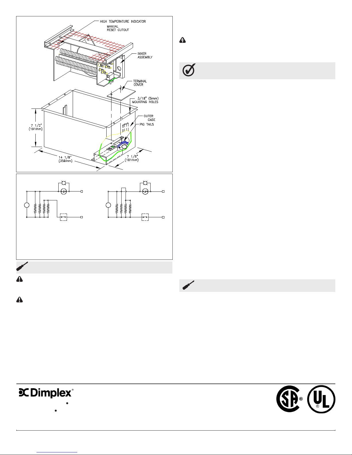
FIGURE 3
FACTORY CONNECTION
240V 1500W 6.25A
For 240V 750W,
Disconnect 2-6, 3-7.
Maintenance
120V 1500W 12.5A
Disconnect cutout black lead from
#1 and #2, and connect leads
“M” and “R”. Add yellow jumper
provided between leads #1, #2, #3
AND #4, Red lead, Motor lead.
FIELD CONNECTION
CAUTION: Before removing the front cover for cleaning,
make certain the power has been turned off at the circuit
breaker panel.
CAUTION: Allow adequate time for the element and body
casing to cool before attempting to work on the heater.
The FFIH series contain no moving parts. Since the
appliance contains no moving parts little maintenance is
required beyond vacuum cleaning. It is however essential
that the heater is not operated with an accumulation of dust
or dirt on the element, as this can cause a build up of heat
and eventual damage. For this reason the heater must be
inspected regularly, depending upon conditions and at least
at yearly intervals. Once cleaning is complete replace the
front cover and restore power.
WARNING: The user can perform cleaning ONLY. All
other servicing should be performed by qualied service
personnel.
Warranty
The Manufacturer warrants the heating elements and
components of the enclosed product against any defect in
material or workmanship for a period of one year from the
date of purchase. In full satisfaction of any claims under
this Warranty the Manufacturer will repair or replace without
charge, in its factory or in the eld as it alone may decide,
any parts which in its opinion are defective.
The Manufacturer shall not be responsible for any
transportation or shipping costs in relation to such repair
or replacement except as specically assumed by it.
Misuse of this product or repairs by persons other than
the Manufacturer’s authorized personnel without the
Manufacturer’s written approval, will void this Warranty.
This Warranty is in lieu of all other warranties or conditions
whether express or implied including but not limited to those
of merchantability or tness for purpose and shall constitute
the sole remedy of the Purchaser and the sole liability of the
Manufacturer in respect of the sale of the product, whether
in the nature of breach or breach of fundamental term, or of
negligence or otherwise.
The Manufacturer shall not be liable for any special, indirect
or consequential damages or for any damages resulting from
removal or replacement of a heater subject to warranty claim
without the Manufacturer’s authorization.
This Warranty is transferable by the original consumer
purchaser of the product. Any claims under this Warranty
must be submitted in writing to the Service Manager, Dimplex
North America Ltd., 1367 Industrial Rd., Cambridge, Ontario
N1R 7G8, Canada.
Replacement Parts
Motor . . . . . . . . . . . . . . . . . . . . . . . . . . . . . . . . . . . . 2000280500RP
Fan Blade . . . . . . . . . . . . . . . . . . . . . . . . . . . . . . . . 5300130200RP
Element . . . . . . . . . . . . . . . . . . . . . . . . . . . . . . . . . . 2200160001RP
Limit Control Thermo Disk. . . . . . . . . . . . . . . . . . . . . . .L82-163ARP
High Limit Kit . . . . . . . . . . . . . . . . . . . . . . . . . . . . . . . . A64-019ARP
Convenience Outlet Kit . . . . . . . . . . . . . . . . . . . . . . . . A64-12A-1RP
1367 Industrial Road Cambridge ON Canada N1R 7G8
1-888-346-7539 www.dimplex.com
In keeping with our policy of continuous product improvement, we reserve the right to make changes without notice.
© 2011 Dimplex North America Limited
www.dimplex.com2
 Loading...