

Page 1
08/53302/0 (UK) Issue 1
EvoRad2BTA
The product complies with the European Safety Standards EN60335-2-30 and the European Standard Electromagnetic Compatibility (EMC) EN55014, EN60555-2
and EN60555-3 These cover the essential requirements of EEC Directives 2006/95/EC and 2004/108/EC
Page 2
2
1
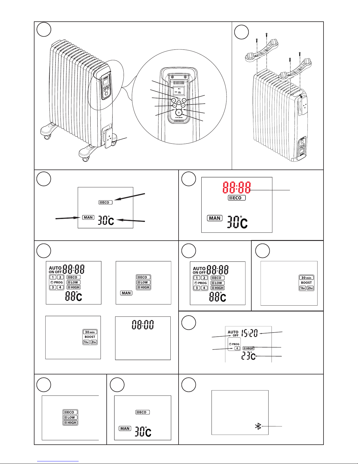
Bluetooth
Neon
Standby
LCD Display
Programme
Temperature
Increase
Cable wrap &
plug storage
Temperature
Decrease
Mode
Heat Neon
Mains neon
3
Desired
Temperature
Selected
Mode
Selected Heat
Seng
Auto Mode
Standby Mode
Boost Mode
Manual Mode
4
5 6
7
Flashing
8 9
10
11
Time for next status
change (ON at 15:20)
Heat seng
Set temperature
Heat status
Acv
e segment
Flashing
Page 3

Dimplex
Model : EvoRad2BTA
Important Safety Advice
IMPORTANT: If the appliance is damaged,
check immediately with the supplier before
installation and operation.
This appliance can be used by children aged
from 8 years and above and persons with
reduced physical, sensory or mental capabilities
or lack of experience or knowledge if they
have been given supervision or instruction
concerning the use of the appliance in a safe
way and understand the hazards involved.
Children shall not play with the appliance.
Cleaning and user maintenance shall not be
made by children without supervision.
Children of less than 3 years should be kept
away unless continuously supervised. Children
aged from 3 years and less than 8 years shall
only switch on/off the appliance provided that
it has been placed or installed in its intended
normal operating position and they have been
given supervision or instruction concerning
the use of the appliance in a safe way and
understand the hazards involved. Children
aged from 3 years and less than 8 years shall
not plug in, regulate and clean the appliance
or perform user maintenance.
CAUTION: Some parts of this product can
become very hot and cause burns. Particular
attention has to be given where children and
vulnerable people are present.
This heater carries the warning symbol
indicating that it must not be covered.
DO NOT use the heater in the immediate
surroundings of a bath, a shower or a swimming
pool.
WARNING: This heater must not be used in
a bathroom.
DO NOT place the heater directly below a xed
socket outlet.
WARNING: In order to avoid overheating, do
not cover the heater.
We recommend that you open a window to
ventilate the room when using the heater for
the rst time.
Unplug the heater when not required for long
periods.
IMPORTANT: If the mains lead of this appliance
is damaged, it must be replaced by the
manufacturer or its service agent or a similarly
qualied person in order to avoid a hazard.
DO NOT use the heater where gas, petrol, paint
or other inammable goods are used or stored.
The heater is designed for operation on an AC electricity supply, and is suitable
for use in domestic dwellings and similar indoor locations.
Always ensure that the appliance is stood on a rm, level base near to, but
not directly beneath, a suitable xed socket outlet.
The heater is tted with castors and a handle for ease of movement.
It is supplied with a cord and plug ready for use.
The supply cord should be uncoiled before use (see ‘Storage’).
DO NOT pull the heater along by the mains lead.
Important - The heater must only be operated with the wheels and castors
tted and in the upright position as shown in Fig. 1.
Warning – The heater complies with stringent safety standards but to ensure
efcient operation SURFACES OF THE HEATER WILL BECOME HOT
AND CONTACT WITH THESE AREAS SHOULD BE AVOIDED, particularly
between the ns on the top and sides.
Electrical
WARNING – THIS APPLIANCE MUST BE EARTHED
If the socket outlets in your home are not of the 13 amp BS1363 type they
will not accept the plug connected to this heater, therefore cut off the plug.
When cut off this plug can constitute a shock hazard if inserted into a socket
outlet. It must therefore be disposed of safely.
Before wiring the appropriate plug please note that the wires in this mains
lead are coloured in accordance with the following code:
GREEN/YELLOW: EARTH
BLUE: NEUTRAL
BROWN: LIVE
Connect the Green/Yellow wire to the terminal marked E or the earth symbol
or coloured Green or Green/Yellow.
Connect the Brown wire to the terminal marked L or coloured Red.
Connect the Blue wire to the terminal marked N or coloured Black. DO NOT
connect the Brown (Live) or the Blue (Neutral) wires to the Earth terminal of
your 13 amp plug. If the terminals of the plug are unmarked or you are in
any doubt, consult a qualied electrician.
Fitting the Castors
IMPORTANT: The castors should only be tted to the outer ns (as shown
in Fig. 2). Fitting the castors to any other n may result in the product
becoming unstable and may topple over during operation.
WARNING: THE HEATER IS HEAVY – TAKE CARE WHEN LIFTING AND
ENSURE THAT IT IS SUPPORTED DURING ASSEMBLY TO PREVENT
IT FROM TOPPLING.
Remove the carton containing the castor assemblies from the packing.
Turn the heater upside down on a carpet or other soft surface to avoid damage
If required request the assistance of a second person. Position a castor bracket
onto the outer n and secure in place using the screws provided (see Fig. 2).
Repeat the process for the other castor, ensuring it is located on the other
end n.
Lift the heater clear of the oor, then turn it back upright and stand it on its
castors as shown in Fig. 1. It is now ready for use.
Positioning the Heater
Select the position for the heater ensuring there is clearance from any furniture
and ttings of at least 300mm above the heater and 150mm each side. The
heater should only be operated on a at stable surface.
Operational modes
The electronic control has four control modes: AUTO, MANUAL, BOOST
and STANDBY mode (see Fig. 4)
In both MANUAL and AUTO mode there are three heat settings options
(see Fig. 5):
‘Intelligent’ Eco Mode - This is the initial default setting, the convector will
automatically start up in this setting once power is applied. The convector
will automatically regulate the room temperature accordingly. In this mode
the convector operates at full power, however the output of the convector is
automatically reduced and regulated as the room temperature approaches
the desired level. This mode optimises energy use by calculating the most
efcient and effective way to achieve the desired temperature setting. The
desired room temperature can be adjusted at any time during operation by
pressing the appropriate key.
Low Heat - In this option, the appliance will operate at a low heat setting,
the appliance will automatically cycle at this setting to maintain the room
temperature setting.
High Heat - In this option, the appliance will operate at a high heat setting,
the appliance will automatically cycle at this setting to maintain the room
temperature setting.
Press the Mode key,‘ ’, to toggle through the modes and the ENTER key
to conrm the mode selection. Note: when selecting the mode if the ENTER
key is not pressed, after 5 seconds the heater will activate the mode shown
on the LCD display.
Initial Operation
When the heater is initially connected to the mains the heater will power
up in MANUAL mode with a set temperature of 30˚C. The Mains and Heat
indication neon will be lit and the LCD display will be as per Fig.6. For
subsequent operations the unit will power up in its previous state, i.e. if it was
in the boost mode when the unit was plugged out when power is reinstated
it will resume in boost mode.
THESE INSTRUCTIONS SHOULD BE READ CAREFULLY AND RETAINED FOR FUTURE REFERENCE
Page 4

Setting the Time
To set the time press and hold ‘ ’ for two seconds, the time digits will begin
ashing (see Fig. 7). Press the ‘ ’ or ‘ ’ buttons to set the time and press
ENTER to conrm. The heater will revert to the previous operational mode.
Standby Mode
With the heater ON, if the button is pressed, the heater will go into standby
mode; the heater switches off, the LCD will display the current set time, only
the mains neon remains illuminated. On pressing the button again the
heater will come on in Manual mode and with a set point setting of 25 ˚C.
Manual Operation
Repeatedly press the ‘ ’ button until the manual mode is visible on the LCD
and conrm the mode selection by pressing ENTER. Use the arrow keys
to select the desired heat setting (see Operational modes for heat setting
details) and conrm the selection by pressing the ENTER key. The desired
temperature can be adjusted at any point during the Manual mode operation,
see Setting the Desired temperature.
Auto mode Operation
Repeatedly press the ‘ ’ button until the Auto mode is visible on the LCD
(see Fig.8) and conrm the mode selection by pressing ENTER. The heater
will operate as per the pre-programmed time and temperature prole (see Setting the Timer Prole). Note: if no timer prole has been set it will not be
possible to select ‘Auto’ mode, it is necessary to set up a time program before
Auto mode can be selected.
During Auto mode operation the LCD display will show the current heat status,
the active programme segment, the time for the next status change, the heat
setting and the set temperature (see Fig.10).
Boost mode Operation
Repeatedly press the ‘ ’ button until the Boost mode is visible on the LCD
(see Fig.9) and conrm the mode selection by pressing ENTER. Once the
boost mode is activated it will be necessary select the boost period, there are
three periods available to choose from, 30 minutes, 1 hour and 2 hours. Use
the arrow keys to select the desired boost period and conrm the selection
using the ENTER key. The default heat setting is ECO mode and the set
temperature is 25˚C. The set temperature can be adjusted if desired, see
Setting the Desired temperature. When the boost mode is active the LCD
display will show the boost mode, timer period selected and the desired set
temperature. The time display will toggle between the current time and time
remaining for the selected boost period.
Frost protection mode
The appliance has a frost protection mode. This setting is useful in areas such
as garages to assist in the prevention of frost damage. In Manual mode, if
the thermostat is set to its minimum setting ‘5°C’, the heater will cycle ON
and OFF to maintain a temperature of approximately 5°C and help protect
against frosty conditions. The frost protection symbol will be displayed on
the LCD display when frost protection mode is activated.
Indicator Neons
Mains On Neon: The mains neon, (see Fig. 1), remains illuminated when
the power is supplied to the product. Note: This does not indicate whether
the heating elements are on.
Heat Neon: Heat neon remains on when the heating element is active. Once
the desired temperature is reached and the element turns off, the heat neon
will indicate this by remaining off.
Bluetooth Neon: The Bluetooth neon will remain illuminated while
successfully paired to another device.
Setting the Desired Temperature
The desired temperature can be set using the ‘ ’ or ‘ ’ keys. The
temperature can be set from 5˚C to 30˚C and this will be shown on the display.
When the temperature is reached the heater will automatically switch OFF. If
the ambient temperature drops the heater will come on again automatically.
Setting the Timer Programmes
There are four program segments available, P1, P2, P3 and P4. For each
segment it is possible to set a desired ‘On’ time, ‘Off’ time, Heat mode and
set temperature. It is not necessary to set all four segments if not required.
The default setting is for all segments to be Off. To turn off a pre-programmed
segment it is necessary to set both the ‘On’ time and the ‘Off’ time to 00:00.
In order to set up a time/temperature prole the following steps must be
completed:
1. To activate the programming screen press the ‘ ’ key. The program settings
screen for P1 will be displayed and the time will be ashing. This ashing
time is the ‘On’ time for P1 and can be adjusted using arrow keys. Once the
desired ‘On’ time has been set press the ENTER key to conrm the time.
2. Select a heat setting using the arrow keys and conrm the selection using
the ENTER key.
3. Set the desired temperature using the arrow keys and conrm the setting
using the ENTER key.
4. The ‘Off’ time must then be set by using the arrow keys, it is necessary to
then press the ENTER key to conrm the ‘Off’ time setting.
5. The setup screen will then revert to the P1 ‘On’ time set up screen, at this
point it is possible move to the P2 segment by pressing the ‘ ’ key.
6. If required P2, P3 and P4 segment can be set up using steps 1-4 above.
7. If it is not required to set up P2, P3 and P4 segment at this stage, continue
to press the ‘ ’ key until the heater reverts to the previous operational mode.
Alternatively if no keys are pressed the programming mode will time out and
revert to the previous operational mode.
Remote Bluetooth Operation
The appliance can be controlled remotely using a smartphone or similar
device. To facilitate this remote operation it is necessary to rst download
the Dimplex app. The app is available on both android and IOS
devices and is available free from the Apple or Android App store. The App is
compatible with Android version 4.3 and above and IOS version 5 and above.
Once the App has been downloaded it is necessary to pair the appliance
with the smartphone to complete the remote setup. Please follow the steps
shown below:
1. Launch the Dimplex app on the smartphone or similar device.
2. To initiate pairing mode on the appliance press and hold the ‘ ’ button for
two seconds. The LCD screen will go blank with the exception of the Bluetooth
logo ashing in the bottom right hand corner, See Fig.11.This indicates that
the device is advertising to be paired with the app.
3. On the smart phone the appliance should now be visible on the pairing
screen, this will be a unique 6 digit code but will always start with EC, for
example ‘ECBC17’. Select this device and press connect to initiate pairing.
4. Once the paring process is complete the app can be used to control the
appliance.
5. Once paired successfully the Bluetooth logo will stop ashing and the
Bluetooth neon will be illuminated.
Safety in use
This appliance incorporates a number of safety devices. In addition to the
‘Important Safety Advice’ section your attention is drawn to the following;
Tilt Switch
The tilt switch will prevent the heater from working if it is accidentally tipped
over on its side. If the radiator is tipped over while it is hot, disconnect the
power and allow it to cool, then stand the radiator back upright. Reconnect
the power - normal operation should be resumed.
Safety Overheat Protection
For your safety this appliance is tted with a thermal cut-out. In the event
that the product overheats for some reason, the cut-out prevents excessive
temperatures on the product by cutting the power to the heater. Once the
heater has cooled down, it will reset automatically, it will continue to cycle on
and off automatically until the reason for overheating is removed.
Storage
If the heater is not required for long periods, for example during the summer,
it should be stored in a dry place and preferably covered to prevent the
accumulation of dirt and dust. The supply cord should be neatly coiled around
the cable wrap and the plug stored in the cable wrap moulding.
Cleaning
WARNING - ALWAYS DISCONNECT THE POWER SUPPLY BEFORE
CLEANING THE HEATER.
Do not use detergents, abrasive cleaning powder or polish of any kind on
the body of the heater.
Allow the heater to cool, then wipe with a dry cloth to remove dust
and a damp cloth (not wet) to clean off stains. Be careful not to allow
moisture in to the heater.
Recycling
For electrical products sold within the European Community.
At the end of the electrical products useful life it should not be
disposed of with household waste. Please recycle where facilities
exist. Check with your Local Authority or retailer for recycling
advice in your country.
After Sales Service
Your product is guaranteed for 3 years from the date of purchase The 3 year
guarantee is extended for an additional 2 years when you register the product
with Dimplex, within 28 days of purchase. If you do not register the product with
Dimplex within 28 days, your product will remain guaranteed for 3 years only.
Within the extended warranty period we undertake to repair or exchange this
product free of charge providing:
a) Proof of purchase such as a sales receipt can be provided, showing
that the appliance was bought within the 36-months prior to registering
the defect/fault.
b) The appliance was correctly operated in accordance with the
manufacturer’s instructions and used solely for domestic purposes.
c) The defect/fault was not as a result of accident, misuse, unauthorised
modication or inexpert repair
Your rights under this guarantee are additional to your statutory rights, which
in turn are not affected by this guarantee.
Validation of extended warranty
To validate your extended warranty register with us online at http://register.
dimplex.co.uk
N.B. Each qualifying product needs to be registered with Dimplex individually.
Please note that the extended warranty is only available in the UK and
Ireland
[c] Dimplex UK Limited
All rights reserved. Material contained in this publication may not be reproduced in whole or in part, without prior permission in writing of Dimplex UK Limited.
 Loading...