

Page 1
Electric Unit Heaters
EUL-B & EUS-B Series
IMPORTANT INSTRUCTIONS
When using electrical appliances, basic precautions should always
be followed to reduce the risk of re, electric shock, and injury to
persons, including the following:
1. Read all instructions before using the heater.
2. The heater is hot when in use. To avoid burns, do not let bare
skin touch hot surfaces. The trim around the heater outlet becomes hot during heater operation. Keep combustible materials,
such as furniture, pillows, bedding, papers, clothes, and curtains
at least 3 ft (0.9 m) from the front of the unit and keep them away
from the sides and rear.
3. Extreme caution is necessary when any heater is used by or
near children or invalids and whenever the unit is left operating
and unattended.
4. Do not operate any heater after it malfunctions. Disconnect
power at the service panel and have the heater inspected by a
reputable electrician before reusing.
5. Do not use outdoors.
6. To disconnect the unit, turn the controls off, and then switch off
at main power supply panel.
7. Do not insert or allow foreign objects to enter any ventilation or
exhaust opening as this may cause an electric shock or re, or
damage to the heater.
8. To prevent a possible re, do not block air intake or exhaust in
any manner.
9. All electrical heaters have hot and arcing or sparking parts inside. Do not use in areas where gasoline, paint, or ammable
liquids are used or stored.
10. Do not modify this heater. Use it only as described in this manual. Any other use not recommended by the manufacturer may
cause re, electric shock or injury to persons.
accessory wall bracket, catalogue EULSWB. The wall bracket
attaches to the centre hole of unit mounting bracket.
WIRING
WARNING: BE SURE ELECTRICITY IS TURNED OFF AT
MAIN SWITCH BEFORE WIRING. ALL WIRING TO BE IN
ACCORDANCE WITH LOCAL AND NATIONAL ELECTRIC
CODES. HEATER MUST BE GROUNDED AS A PRECAUTION
AGAINST ELECTRIC SHOCK.
1. Connect heater only to the voltage and frequency specied on
the nameplate.
2. All wiring to be inaccordance with local codes and National Electrical Code.
3. Remove screws securing access door and swing door down to
expose wiring and control compartment.
4. Knockouts are provided at the back of and one side of the heater
for power and control wiring. (Figure 2) In combinations of: 1
⅜ in (35mm) and 1 ⅛ in (29mm), and 1 ⅛ in (29mm) and ⅞ in
(22mm).
5. A ground terminal is provided. The ground wire should be connected before making other connections.
6. Rough-in branch circuit wiring to the heater using wire rated for
140°F (60 °C). Wire heater according to diagram attached to
the access door.
7. Electrical accessory options are shown on the heater wiring dia-
gram connected by a dashed line.
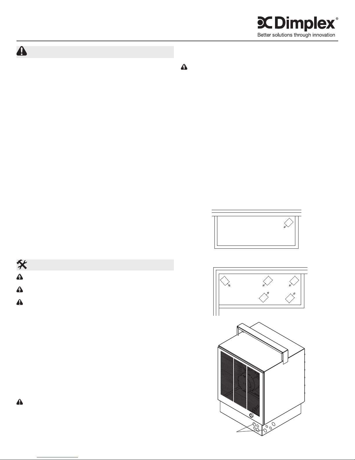
Figure 1
EXPOSED OUTSIDE WALL
SAVE THESE INSTRUCTIONS
Installation Instructions
WARNING: Wiring procedures and connections should be in ac-
cordance with the National Electric code (NEC) and local codes.
WARNING: To reduce the risk of re, do not store or use gasoline
or other ammable vapors or liquids in the vicinity of the heater.
CAUTION: High temperature, risk of re, keep electrical cords,
drapery, furnishings, and other combustibles at least 3 ft (0.9 m)
from the front of the heater.
HEATER LOCATION
Unit heaters should be located along outside walls to provide perimeter air circulation. The discharge air should wipe the walls without
blowing directly on them. (Figure 1)
• Small rooms - can be heated by one or two units. Locate the
unit heater(s) to set up circular air movement within the space.
• Large rooms - requiring multiple unit installations. Units should
be located so that the discharge air from one unit supports the
discharge from another unit and sets up a circular movement.
• Remove Thermostats - should be located on interior walls or
posts away from heat sources, cold drafts, and away from heater
discharge air streams.
MOUNTING UNIT HEATER(S)
CAUTION: Heater must be mounted a minimum of 10 in (25.4
cm) from walls and 6 ft (183 cm) above oor with discharge parallel
to or away from wall.
• Ceiling Mounting - The heater comes equipped with a mounting bracket. Fasten to or suspend the heater from the ceiling
using the holes provided in the bracket.
• Wall Mounting - The heater may also be mounted to a wall with
EXPOSED OUTSIDE WALL
WALL
EXPOSED OUTSIDE
Figure 2
Knockouts
SMALL ROOM
LARGE ROOM
7202460001R04
Page 2
Operation
WARNING: This heater must be properly installed before it
is used.
CONTROLS
• Fan Delay - The heater is equipped with a fan delay control. There will be a short delay to enable the heating elements to warm up before the fan turns on. The fan will
also remain on for a few moments after the elements are
de-energized.
• Automatic High Limit - Each heater is equipped with automatic reset thermal cutouts. Should these safety switches operate, they will automatically reset once the element
reaches a safe operation temperature, however, the cause
of the high limit condition should be determined and corrected to sure satisfactory operation.
OPTIONAL CONTROLS
• Integral thermostats - All units are available with a built-in
snap-action thermostat. The sensing element is located
in the return air stream to provide accurate temperature
control. The thermostat has a range of 40°F (5°C) (low) to
100°F (38°C) (high). It can be manually operated or rendered tamper-proof as desired. This control can be eldmounted or factory mounted.
• Remote Line Voltage Thermostat - All units can be con-
nected to a line-voltage remote thermostat. A special control terminal block is provided in all units to facilitate easy
connection of the remote thermostat control wiring.
• Remote Low Voltage Thermostat with Relay - A low volt-
age transformer/relay can be eld or factory installed with
the unit for remote low voltage thermostatic control. The
special control terminal block is utilized for this optional
control feature.
• Fan-Only Switch - An optional fan-only switch is available
for integral mounting within the unit. This switch provides
continuous fan-operation, independent of the built-in or
optional remote thermostatic control, which is effective in
eliminating air stratication.
START UP
1. Before the unit is energized, the discharge louvres should
be adjusted for desired air deection.
2. Check to see that all controls and optional accessories are
operation properly.
Maintenance
CAUTION: Before removing the front cover for cleaning,
make certain the power has been turned off at the circuit
breaker panel.
CAUTION: Allow adequate time for the element and body
casing to cool before attempting to work on the heater.
1. Under normal conditions, the heater should be cleaned
once a year. DISCONNECT ALL POWER before cleaning
or servicing the heater.
2. All motors are lubricated for extended life operation, and
will not have to be oiled.
Warranty
The Manufacturer warrants the heating elements and components of the enclosed
product against any defect in material or workmanship for a period of one year
from the date of purchase. In full satisfaction of any claims under this Warranty the
Manufacturer will repair or replace without charge, in its factory or in the eld as it
alone may decide, any parts which in its opinion are defective.
The Manufacturer shall not be responsible for any transportation or shipping costs in
relation to such repair or replacement except as specically assumed by it. Misuse
of this product or repairs by persons other than the Manufacturer’s authorized
personnel without the Manufacturer’s written approval, will void this Warranty.
This Warranty is in lieu of all other warranties or conditions whether express or
implied including but not limited to those of merchantability or tness for purpose
and shall constitute the sole remedy of the Purchaser and the sole liability of the
Manufacturer in respect of the sale of the product, whether in the nature of breach
or breach of fundamental term, or of negligence or otherwise.
The Manufacturer shall not be liable for any special, indirect or consequential
damages or for any damages resulting from removal or replacement of a heater
subject to warranty claim without the Manufacturer’s authorization.
This Warranty is transferable by the original consumer purchaser of the product.
Any claims under this Warranty must be submitted in writing to the Service Manager,
Dimplex North America Ltd., 1367 Industrial Rd., Cambridge, Ontario N1R 7G8,
Canada.
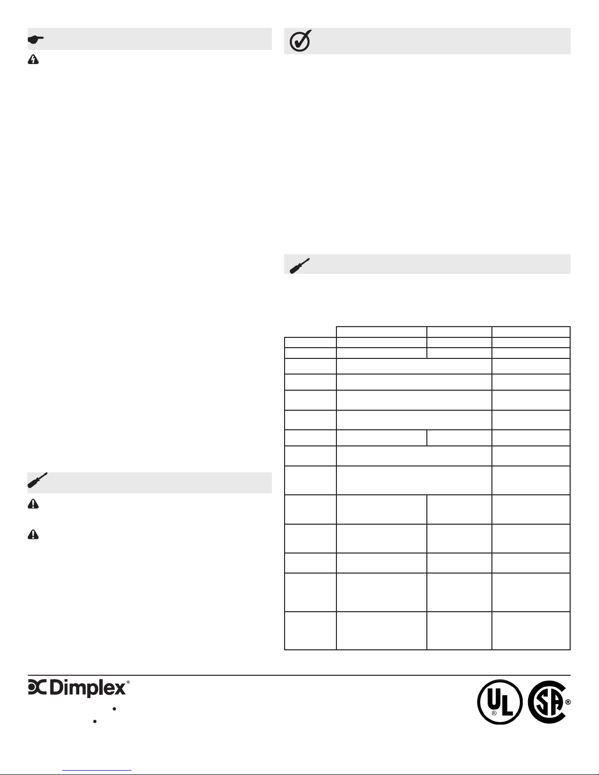
Replacement Parts
Thermostat ......................................03005043RP
Control Knob .....................................02028016RP
Control Fuse .....................................04005103RP
Terminal Block ..................................4000040600RP
Grille ........................................30006159-SARP
15-25kW 30kW 40-50kW
Fan Blade 02000017RP 02000018RP 02000045RP
Motor 2000080200RP 2000090100RP 3024019RP
Casing 30006730-SARP 30006851-SARP
Louver 30000013-SARP 30006855-SARP
Hi Limit
Cutout
Fan Delay
Relay
Capacitor 00857007RP 02007005RP N/A
Contactor
Transformer
208V
Elements
240V
Elements
347V
Elements
480V
Elements
600V
Elements
15kW: 2200270100RP
20kW: 2200270500RP
25kW: 2200270800RP
15kW: 2200270200RP
20kW: 2200270100RP
25kW: 2200270900RP
15kW: 2200271400RP
20kW: 2200271600RP
15kW: 2200270300RP
20kW: 2200270600RP
25kW: 2200271000RP
15kW: 2200270400RP
20kW: 2200270700RP
25kW: 2200271100RP
*All units have 6 elements unless otherwise indicated
03005039RP 03005046RP
06942602RP 03005044RP
2400160300RP
2400161300RP (above 48A)
347V: 2100080022RP
480V: 2100080011RP
600V: 2100080012RP
2200271800RP N/A
N/A N/A
N/A N/A
40kW: 02038336RP
2200271200RP
60kW: 02038338RP
40kW: 02038337RP
2200271300RP
60kW: 02038338RP
2400160200RP
480V: 02005869RP
600V: 03005045RP
(9 elements/unit)
(9 elements/unit)
(9 elements/unit)
(9 elements/unit)
1367 Industrial Road Cambridge ON Canada N1R 7G8
1-888-346-7539 www.dimplex.com
In keeping with our policy of continuous product improvement, we reserve the right to make changes without notice.
© 2014 Dimplex North America Limited
 Loading...