

Dimplex EUH03B31T, EUH03B34CT, EUH03B41T, EUH03B51CT, EUH03B73CT Installation And Operation Manual
...Page 1
Electric Unit Heaters
EUH-B Series
IMPORTANT INSTRUCTIONS
When using electrical appliances, basic precautions should
always be followed to reduce the risk of re, electric shock
and injury to person, including the following:
Read all instructions before using this heater.1.
A heater has hot and arcing or sparking parts inside. Do 2.
not use it in areas where gasoline, paint or ammable
liquids are used or stored.
This heater is hot when in use. To avoid burns, do not let 3.
bare skin touch hot surfaces. If provided, use handles
when moving this heater. Keep combustible materials
such as: furniture, pillows, bedding, papers, clothes and
curtains away from heater.
To prevent a possible re, do not block air intakes or 4.
exhaust in any manner. Do not use on soft surfaces like
a bed where openings may become blocked.
Do not insert or allow foreign objects to enter any venti-5.
lation or exhaust opening as this may cause an electric
shock or re, or damage the heater.
SAVE THESE INSTRUCTIONS
Installation Instructions
WARNING: Wiring procedures and connections should
be in accordance with the National Electric code (NEC) and
local codes.
FOR HORIZONTAL OR VERTICAL AIRFLOW
PERMANENT OR SUPPLEMENTARY ELECTRIC FORCED
AIR HEATING FROM THE SAME VERSATILE UNIT
These heavy-duty heaters provide spot heating for hard to
heat areas, or they can be used as the primary source of
heat for areas not reached by an existing heating system.
The fan and motor are carefully matched to insure quiet,
trouble-free operation and fan blades are precision balanced
before installation.
Heaters in all capacities (3, 5, 7-1/2, 10 or 12kw) have the
same dimensions, and use the same mounting brackets. All
components and controls, including thermostat, transformers,
relays, and switches are enclosed inside the case. Wiring
is simple and all heaters can operate from a single power
source.
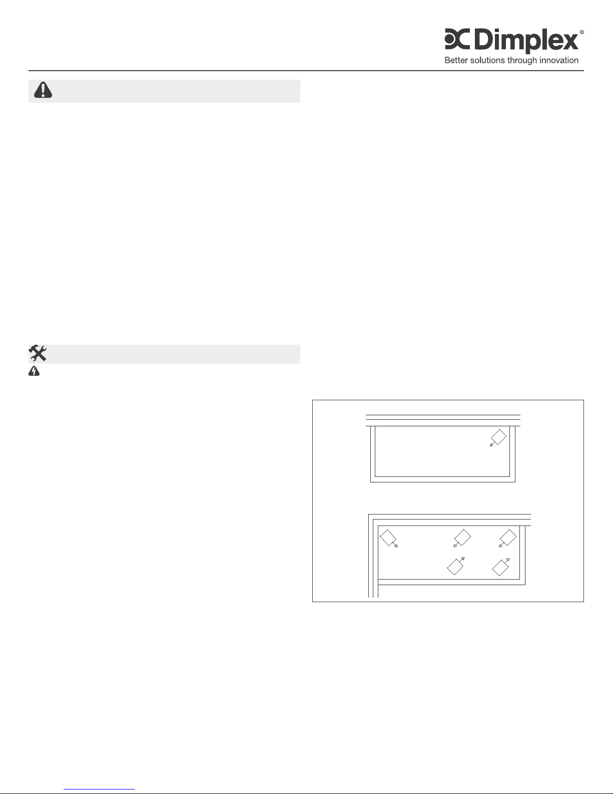
HEATER LOCATION
Unit heaters should be located along outside walls to provide
perimeter air circulation. The discharge air should wipe the
walls without blowing directly on them. (Figure 1)
Small rooms• - can be heated by one or two units.
Locate the unit heater(s) to provide circular air movement
within the space.
Large rooms • - requiring multiple unit installations. Units
should be located so that the discharge air from one unit
supports the discharge from another unit and provides a
circular air movement.
Remote thermostats • - should be located on interior
walls or posts away from heat sources, cold drafts, and
away from heater discharge streams.
MOUNTING UNIT HEATER(S)
Heater should be mounted a minimum of ten (10) inches
from walls and six (6) feet above oor (8 feet for vertical air
ow) with the discharge parallel to or away from wall.
MOUNTING BRACKET • - The heater is shipped with
a mounting bracket packed separately in the carton.
Secure the bracket to threaded attachment points on
the sides of the heater with two bolts (provided). Select
desired angle of tilt (Horizontal, 15, 30, 45, 60, 75, or
Vertical), remove corresponding knockouts on sides
of the heater, then screw the remaining two bolts into
the threaded holes in the bracket so that the bolts pass
through the knockout holes. The unit is now ready for
hanging.
CEILING MOUNTING• - Fasten the heater securely to
the ceiling using the center hole in the bracket or the two
holes on either side of the center hole. The Unit mounting
bracket may be attached directly to the ceiling.
WALL MOUNTING• - The heater may also be mounted
to a wall with accessory wall bracket, Part # EUHWB.
The wall bracket attaches to the center hole of the unit
mounting bracket.
Figure 1
EXPOSED OUTSIDE
EXPOSED OUTSIDE WALL
SMALL ROOM
EXPOSED OUTSIDE WALL
WALL
LARGE ROOM
WIRING:
Connect the heater only to the voltage and frequency 1.
specied on the nameplate.
All wiring to be in accordance with local and national 2.
electric codes.
Remove two screws securing the access door (See 3.
Figure 2) and swing the door down to expose the wiring
and control compartment.
Three knockouts are provided at the back of the heater 4.
for power and control wiring. (See Figure 2)
Rough-in branch circuit wiring to the heater using wire 5.
7202450001R06
Page 2
rated for 75 degrees C. Wire heater supply according to
diagram attached to the access door.
Figure 2
Remove
screw, from
each side
Supply Entry
Knockouts
Operation
CONTROLS (Factory installed)
Fan delay• - The heater is equipped with a fan delay
control. The fan will remain on for a few moments after
the elements are de-energized.
Automatic High Limit• - Each heater is equipped with
automatic reset thermal cutouts located above the
elements. Should these safety switches operate, they
will automatically reset once the element reaches a safe
operating temperature, however the cause of the high
limit condition should be determined and corrected to
insure satisfactory operation.
Thermostat• - All heaters are equipped with a hydraulic
type thermostat which has a nominal operating range of
40F (low) to 100F (high).
OPTIONAL CONTROLS (Field installed)
Remote line voltage thermostat• - An optional remote
line voltage thermostat may be used to control the
unit. Field connections may simply be connected to the
control terminal block located in the wiring compartment
in accordance with with the wiring diagram attached to
the access door.
CAUTION: Disconnect the built-in thermostat
Remote Low voltage thermostat with relay• - An
optional low voltage thermostat/relay kit may be used
to control the unit (Catalogue #EUAR11, 120V primary;
EUAR21, 208V primary; EUAR31, 240V primary;
EUAR41, 277V primary). The relay is installed through
the hole provided in the back left corner of the blower
deck. Power connections are made to the control
terminal block located in the wiring compartment in
accordance with the wiring diagram attached to the
access door. A knockout is provided on the left side of
the heater for the 24 volt thermostat control wiring. It is
important that the plastic insulation bushing be installed
into the knockout hole before running low voltage
control wiring. The thermostat is installed and wired in
accordance with the instructions packaged with the kit.
CAUTION: Disconnect the built-in thermostat
Fan only Switch• - An optional “Fan only” switch kit
(Catalogue EUAF2) is available for eld installation in
the unit. The fan switch is mounted in the space provided
adjacent to the built-in thermostat located at the front
of the unit. Field connections are made at the control
terminal block in accordance with the unit wiring diagram.
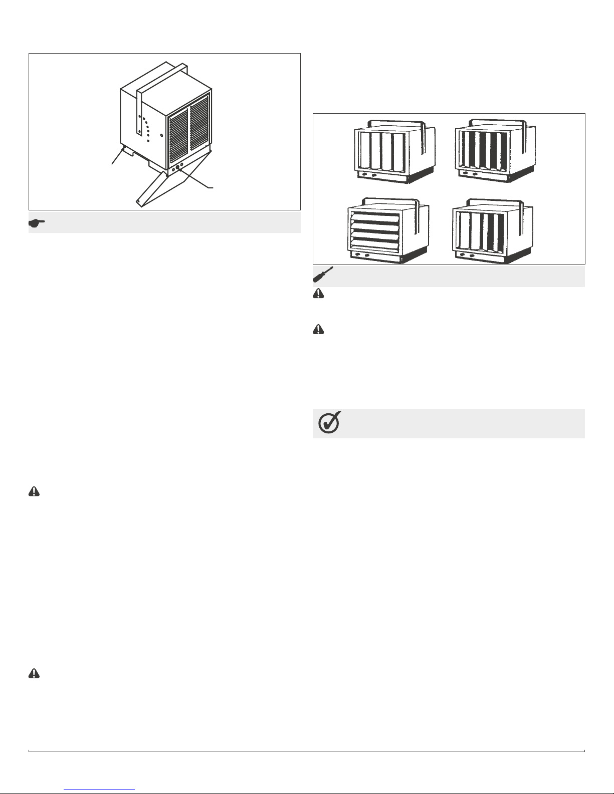
START-UP:
Before the unit is energized, the discharge louvers 1.
should be be adjusted for desired air deection. Louvers
may be adjusted for either horizontal or vertical air
deection by rotating the louvre frame. (See gure 3)
Check to see that all controls and optional accessories 2.
are operating properly.
Figure 3
Maintenance
CAUTION: Before removing the front cover for cleaning,
make certain the power has been turned off at the circuit
breaker panel.
CAUTION: Allow adequate time for the element and body
casing to cool before attempting to work on the heater.
Under normal conditions, the heater should be cleaned 1.
once a year. DISCONNECT ALL POWER before
cleaning or servicing the heater.
All motors are lubricated for extended life operation, and 2.
will not have to be oiled.
Warranty
The Manufacturer warrants the heating elements and components
of the enclosed product against any defect in material or
workmanship for a period of one year from the date of purchase. In
full satisfaction of any claims under this Warranty the Manufacturer
will repair or replace without charge, in its factory or in the eld as it
alone may decide, any parts which in its opinion are defective.
The Manufacturer shall not be responsible for any transportation
or shipping costs in relation to such repair or replacement except
as specically assumed by it. Misuse of this product or repairs by
persons other than the Manufacturer’s authorized personnel without
the Manufacturer’s written approval, will void this Warranty.
This Warranty is in lieu of all other warranties or conditions
whether express or implied including but not limited to those of
merchantability or tness for purpose and shall constitute the sole
remedy of the Purchaser and the sole liability of the Manufacturer in
respect of the sale of the product, whether in the nature of breach or
breach of fundamental term, or of negligence or otherwise.
The Manufacturer shall not be liable for any special, indirect or
consequential damages or for any damages resulting from removal
or replacement of a heater subject to warranty claim without the
Manufacturer’s authorization.
This Warranty is transferable by the original consumer purchaser
of the product. Any claims under this Warranty must be submitted
in writing to the Service Manager, Dimplex North America Ltd., 1367
Industrial Rd., Cambridge, Ontario N1R 7G8, Canada.
www.dimplex.com2
Page 3

Replacement Parts
Casing . . . . . . . . . . . . . . . . . . . . . . . . . . . . . 1006060168RP
Fan Delay . . . . . . . . . . . . . . . . . . . . . . . . . . 00033002RP
Grill . . . . . . . . . . . . . . . . . . . . . . . . . . . . . . . 30006159-ARP
Louver . . . . . . . . . . . . . . . . . . . . . . . . . . . . . 30006151-ARP
Motor (except for EUH03B11T). . . . . . . . . . 2000270100RP
Motor for EUH03B11T. . . . . . . . . . . . . . . . . 2000250100RP
Capacitor (except for EUH03B11T) ....... 3200070200RP
Capacitor for EUH03B11T. . . . . . . . . . . . . . 3200070600RP
Terminal Block ....................... 4000040500RP
Control Knob . . . . . . . . . . . . . . . . . . . . . . . . 8800540368RP
Cut-Out . . . . . . . . . . . . . . . . . . . . . . . . . . . . 00009113RP
CATALOG
NO.
EUH03B11T 530020300RP 2600060800RP N/A N/A 2200210100RP
EUH03B21T
EUH03B24CT N/A 2400170900RP 2200210200RP
EUH03B31T N/A N/A 2200210300RP
EUH03B34CT N/A 2400170900RP 2200210300RP
EUH03B41T 2100120100RP N/A 2200210400RP
EUH03B51CT 2100120200RP 2400160300RP 2200211200RP
EUH03B73CT 2100120400RP 2400160300RP 2200210400RP
EUH03B81CT 2100120500RP 2400160300RP 2200212100RP
EUH03B83CT 2100120500RP 2400160300RP 2200211200RP
EUH05B21T 2600060800RP N/A N/A 2200210800RP
EUH05B24CT 2600060200RP N/A 2400170900RP 2200210800RP
EUH05B31T 2600060800RP N/A N/A 2200210500RP
EUH05B34CT 2600060200RP N/A 2400170900RP 2200210500RP
EUH05B41T 2600060800RP 2100120100RP N/A 2200210600RP
EUH05B51CT
EUH05B74CT 2100120400RP 2400170900RP 2200211900RP
EUH05B84CT 2100120500RP 2400170900RP 2200212300RP
EUH08B24CT
EUH08B34CT N/A 2400170900RP 2200210600RP
EUH08B51CT 2100120200RP 2400160300RP 2200211300RP
EUH08B74CT 2100120400RP 2400170900RP 2200211800RP
EUH08B84CT 2100120500RP 2400170900RP 2200212200RP
EUH10B24CT N/A 2400170900RP 2200210800RP
EUH10B34CT N/A 2400170900RP 2200210500RP
EUH10B51CT 2100120200RP 2400160300RP 2200211500RP
EUH10B74CT 2100120400RP 2400170900RP 2200211900RP
EUH10B84CT 2100120500RP 2400170900RP 2200212300RP
EUH12B23CT N/A 2400160300RP 2200210900RP
EUH12B3CT N/A 2400160300RP 2200211000RP
EUH12B74CT 2100120400RP 2400170900RP 2200212000RP
EUH12B84CT 2100120500RP 2400170900RP 2200212400RP
FAN BLADE THERMOSTAT TRANSFORMER CONTACTOR
2600060200RP
5300020100RP
2600060200RP
5300020200RP
ELEMENT
RP NO. QTY/HEATER
N/A N/A 2200210200RP
3
2100120200RP 2400160300RP 2200211500RP
N/A 2400170900RP 2200210500RP
6
1367 Industrial Road Cambridge ON Canada N1R 7G8
1-888-346-7539 www.dimplex.com
In keeping with our policy of continuous product improvement, we reserve the right to make changes without notice.
© 2011 Dimplex North America Limited
3
 Loading...