

Page 1
ELECTRIC UNIT HEATERS
MODEL EUH-B
Installation/ Start-up/ Maintenance
FOR HORIZONTAL OR VERTICAL AIRFLOW
PERMANENT OR SUPPLEMENTARY ELECTRIC FORCED AIR HEATING FROM THE SAME
VERSATILE UNIT
These heavy-duty heaters provide spot heating for hard to heat areas, or they can be used as the
primary
source of heat for areas not reached by an existing heating system.
The fan and motor are carefully matched to insure quiet, trouble-free operation and fan blades are precision
balanced before installation.
Heaters in all capacities (3, 5, 7-1/2, 10 or 12kw) have the same dimensions, and use the same mounting
brackets. All components and controls, including thermostat, transformers, relays, and switches are
enclosed inside the case. Wiring is simple and all heaters can operate from a single power source.
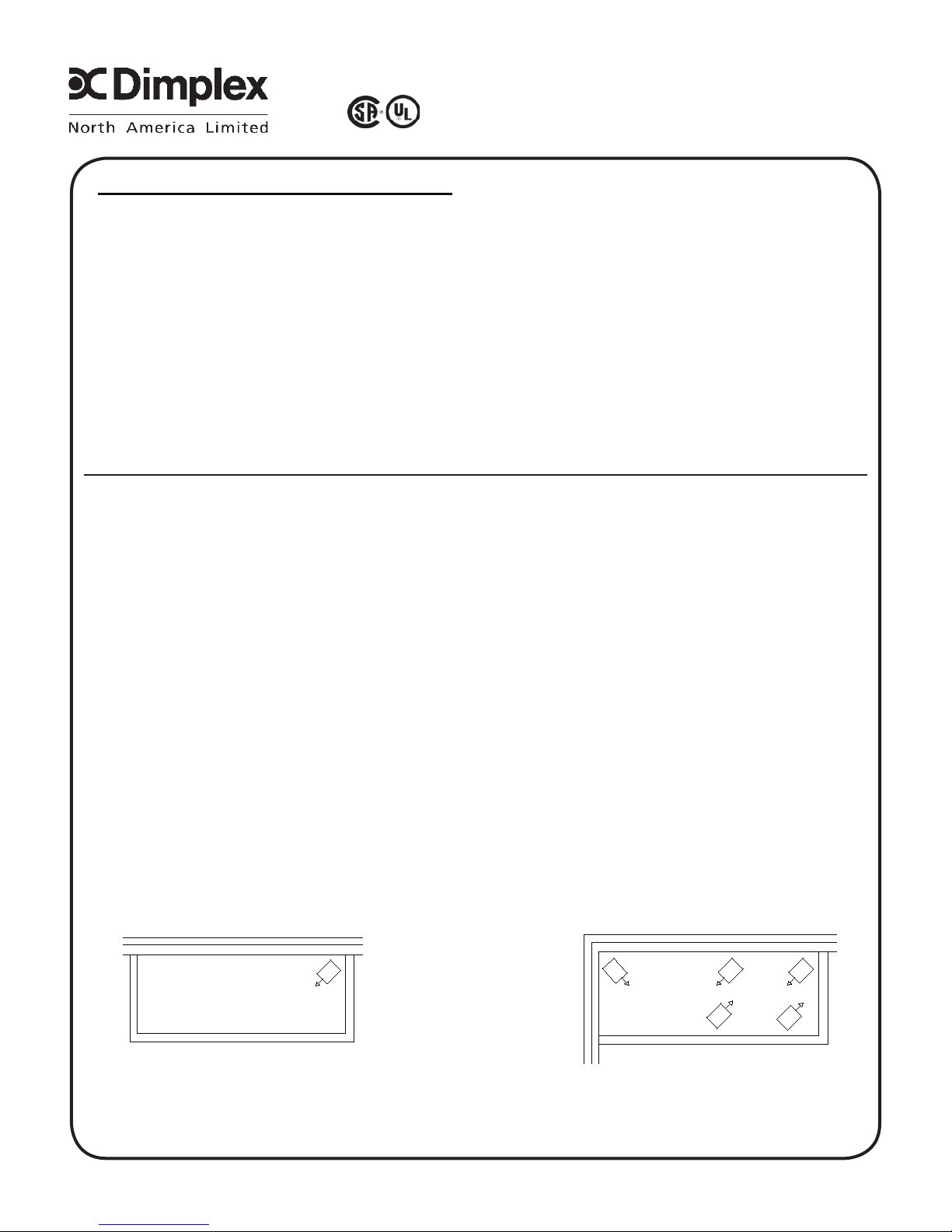
1. HEATER LOCATION: Unit heaters should be located along outside walls to provide perimeter air
circulation. The discharge air should wipe the walls without blowing directly on them. (Figure 1)
a. Small rooms - can be heated by one or two units. Locate the unit heater(s) to provide circular air
movement within the space.
b. Large rooms - requiring multiple unit installations. Units should be located so that the discharge air from
one unit supports the discharge from another unit and provides a circular air movement.
c. Remote thermostats - should be located on interior walls or posts away from heat sources, cold drafts,
and away from heater discharge streams.
2. MOUNTING UNIT HEATER(S): Heater should be mounted a minimum of ten (10) inches from walls
and six (6) feet above fl oor (8 feet for vertical air fl ow) with the discharge parallel to or away from wall.
(See Table A for recommended mounting heights)
a. MOUNTING BRACKET - The heater is shipped with a mounting bracket packed separately in the carton.
Secure the bracket to threaded attachment points on the sides of the heater with two bolts (provided).
Select desired angle of tilt (Horizontal, 15, 30, 45, 60, 75, or Vertical), remove corresponding knockouts
on sides of the heater, then screw the remaining two bolts into the threaded holes in the bracket so that
the bolts pass through the knockout holes. The unit is now ready for hanging.
b. CEILING MOUNTING - Fasten the heater securely to the ceiling using the center hole in the bracket
or the two holes on either side of the center hole. The Unit mounting bracket may be attached directly to
the ceiling.
c.WALL MOUNTING - The heater may also be mounted to a wall with accessory wall bracket,
(Part # EUHWB). The wall bracket attaches to the center hole of the unit mounting bracket.
EXPOSED OUTSIDE WALL
SMALL ROOM LARGE ROOM
FIGURE 1
EXPOSED OUTSIDE WALL
WALL
EXPOSED OUTSIDE
1-888-346-7539
7202450001R05
Page 2
Heater is now ready for wiring
3. WIRING:
a. Connect the heater only to the voltage and frequency specifi ed on the nameplate.
b. All wiring to be in accordance with local and national electric codes.
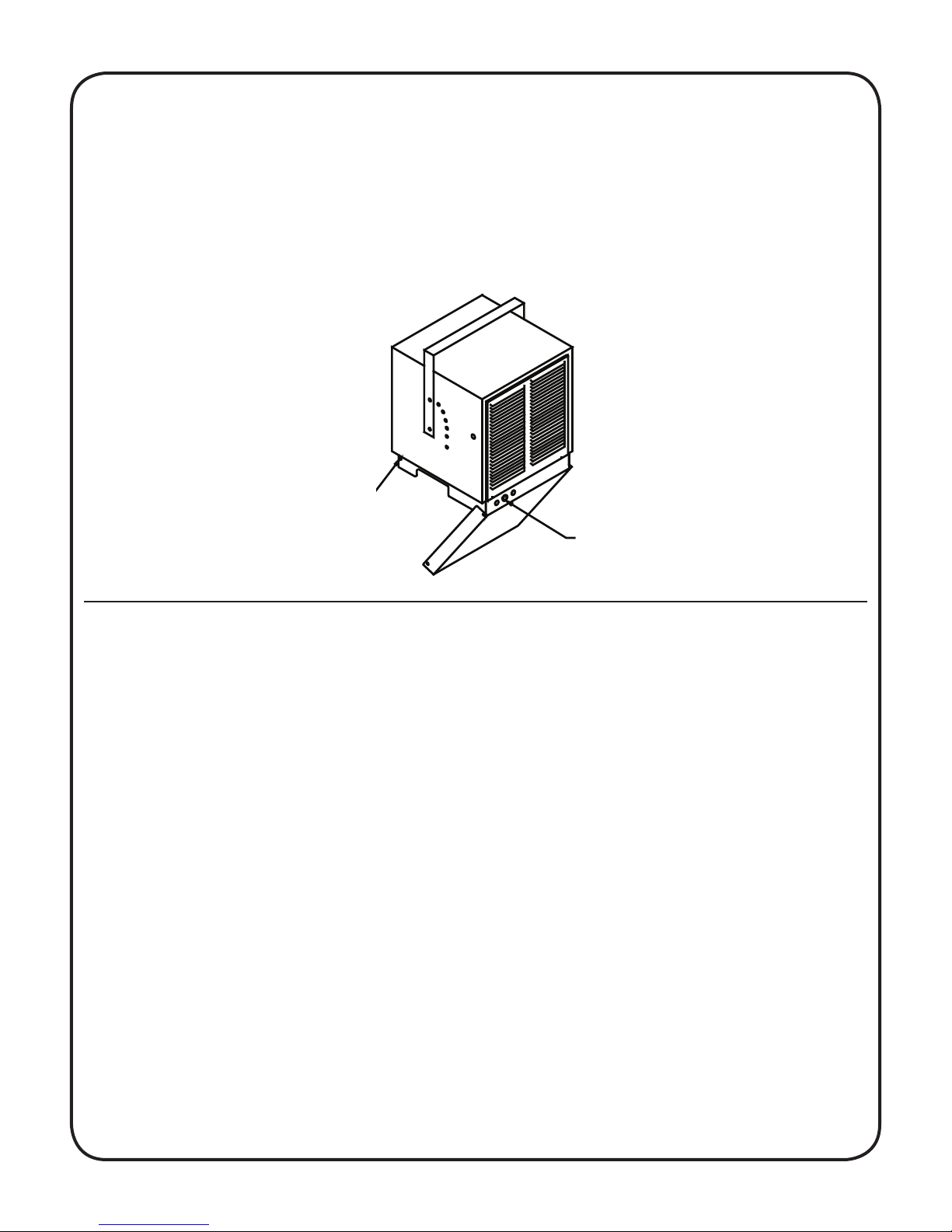
c. Remove two screws securing the access door (See Figure 2) and swing the door down to expose the
wiring and control compartment.
d. Three knockouts are provided at the back of the heater for power and control wiring. (See Figure 2)
e. Rough-in branch circuit wiring to the heater using wire rated for 75 degrees C. Wire heater supply
according to diagram attached to the access door.
REMOVE SCREW,
EACH SIDE
FIGURE 2
SUPPLY ENTRY KNOCKOUTS
4. CONTROLS: Factory installed.
a. Fan delay - The heater is equipped with a fan delay delay control. The fan will remain on for a few
moments after the elements are de-energized.
b. Automatic High Limit - Each heater is equipped with automatic reset thermal cutouts located above the
elements. Should these safety switches operate, they will automatically reset once the element reaches
a safe operating temperature, however the cause of the high limit condition should be determined and
corrected to insure satisfactory operation.
c.Thermostat - All heaters are equipped with a hydraulic type thermostat which has a nominal operating
range of 40F (low) to 100F (high).
5. OPTIONAL CONTROLS: Field installed.
a. Remote line voltage thermostat - An optional remote line voltage thermostat may be used to control
the unit. Field connections may simply be connected to the control terminal block located in the wiring
compartment in accordance with with the wiring diagram attached to the access door.
CAUTION - Disconnect the built-in thermostat
b. Remote Low voltage thermostat with relay - An optional low voltage thermostat/relay kit may be used
to control the unit (Catalogue #EUAR11, 120V primary; EUAR21, 208V primary; EUAR31, 240V primary;
EUAR41, 277V primary). The relay is installed through the hole provided in the back left corner of the
blower deck. Power connections are made to the control terminal block located in the wiring compartment
in accordance with the wiring diagram attached to the access door. A knockout is provided on the left side
of the heater for the 24 volt thermostat control wiring. It is important that the plastic insulation bushing be
installed into the knockout hole before running low voltage control wiring. The thermostat is installed and
wired in accordance with the instructions packaged with the kit.
CAUTION - Disconnect the built-in thermostat
Page 3

c. Fan only Switch - An optional “Fan only” switch kit (Catalogue EUAF2) is available for fi eld installation
in the unit. The fan switch is mounted in the space provided adjacent to the built-in thermostat located at
the front of the unit. Field connections are made at the control terminal block in accordance with the unit
wiring diagram.
6. START-UP:
a. Before the unit is energized, the discharge louvers should be be adjusted for desired air defl ection.
Louvers may be adjusted for either horizontal or vertical air defl ection by rotating the louvre frame.
(See fi gure 3)
b. Check to see that all controls and optional accessories are operating properly.
7.MAINTENENCE:
a. Under normal conditions, the heater should be cleaned once a year. DISCONNECT ALL POWER before
cleaning or servicing the heater.
b.All motors are lubricated for extended life operation, and will not have to be oiled.
FIGURE 3
Page 4

EUH03B11T 530020300RP 2000250100RP 2600060800RP N/A
EUH03B21T N/A
EUH03B24CT N/A
EUH03B31T N/A
EUH03B34CT N/A
EUH03B41T 2600060200RP 21001200100RP
EUH03B51CT 2100120200RP
EUH03B73CT 2100120400RP
EUH03B81CT 2100120500RP
EUH03B83CT 5300020100RP 2100120500RP
EUH05B21T 2600060800RP N/A
EUH05B24CT 2600060200RP N/A
EUH05B31T 2600060800RP N/A
EUH05B34CT 2600060200RP N/A
EUH05B41T 00033001RP 30006159-ARP 30006151-ARP 4000040500RP 2600060800RP 2100120100RP
EUH05B51CT 2000270100RP 2100120200RP
EUH05B74CT 2100120400RP
EUH05B84CT 2100120500RP
EUH08B24CT N/A
EUH08B34CT N/A
EUH08B51CT 2100120200RP
EUH08B74CT 2100120400RP
EUH08B84CT 2600060200RP 2100120500RP
EUH10B24CT N/A
EUH10B34CT 5300020200RP N/A
EUH10B51CT 2100120200RP
EUH10B74CT 2100120400RP
EUH10B84CT 2100120500RP
EUH12B23CT N/A
EUH12B3CT N/A
EUH12B74CT 2100120400RP
EUH12B84CT 2100120500RP
REPLACEMENT PARTS
TRANSFORMERCATALOG NO. FAN BLADE FAN DELAY GRILL LOUVER MOTOR TERM BLOCK THERMOSTAT
Page 5

RP NO. QTY/HEATER
EUH03B11T 3200070600RP N/A 2200210100RP
EUH03B21T N/A 2200210200RP
EUH03B24CT 2400170900RP 2200210200RP
EUH03B31T N/A 2200210300RP
EUH03B34CT 2400170900RP 2200210300RP
EUH03B41T N/A 2200210400RP
EUH03B51CT 2400160300RP 2200211200RP
EUH03B73CT 2400160300RP 2200210400RP
EUH03B81CT 2400160300RP 2200212100RP 3
EUH03B83CT 2400160300RP 2200211200RP
EUH05B21T N/A 2200210800RP
EUH05B24CT 2400170900RP 2200210800RP
EUH05B31T N/A 2200210500RP
EUH05B34CT 2400170900RP 2200210500RP
EUH05B41T N/A 2200210600RP
EUH05B51CT 3200070200RP 1006060168RP 2400160300RP 8800540368RP 00009112RP 2200211500RP
EUH05B74CT 2400170900RP 2200211900RP
EUH05B84CT 2400170900RP 2200212300RP
EUH08B24CT 2400170900RP 2200210500RP
EUH08B34CT 2400170900RP 2200210600RP
EUH08B51CT 2400160300RP 2200211300RP
EUH08B74CT 2400170900RP 2200211800RP
EUH08B84CT 2400170900RP 2200212200RP
EUH10B24CT 2400170900RP 2200210800RP
EUH10B34CT 2400170900RP 2200210500RP 6
EUH10B51CT 2400160300RP 2200211500RP
EUH10B74CT 2400170900RP 2200211900RP
EUH10B84CT 2400170900RP 2200212300RP
EUH12B23CT 2400160300RP 2200210900RP
EUH12B3CT 2400160300RP 2200211000RP
EUH12B74CT 2400170900RP 2200212000RP
EUH12B84CT 2400170900RP 2200212400RP
CATALOG NO. CAPACITOR CASING CONTACTOR CONTROL KNOB CUT-OUT
ELEMENT
 Loading...