

Dimplex ESTHETIC SERIES Instructions Manual
7204310000REV02
“ESTHETIC” CONVECTOR HEATER SERIES
STEP-BY-STEP INSTALLATION (Note: Please read all instructions before installing)
WARNING
The installation of the convector heater must comply with the applicable
Local and/or National Electrical Codes and utility requirements. This
installation should be entrusted to duly qualified personnel where required
by law.
NOTE
Due to the precision of the convector’s control circuits, the unit is highly
sensitive to air drafts, cold floors, etc. To ensure the thermostat operates
efficiently, be sure to carefully choose the units location before installing.
Avoid installing unit in an area that is susceptible to cold drafts, or near a
cold floor.
WARNING
The convector must be installed in a location preventing anyone using a
bath or shower from touching the control devices.
WARNING
The convector must not be located directly below a fixed power outlet.
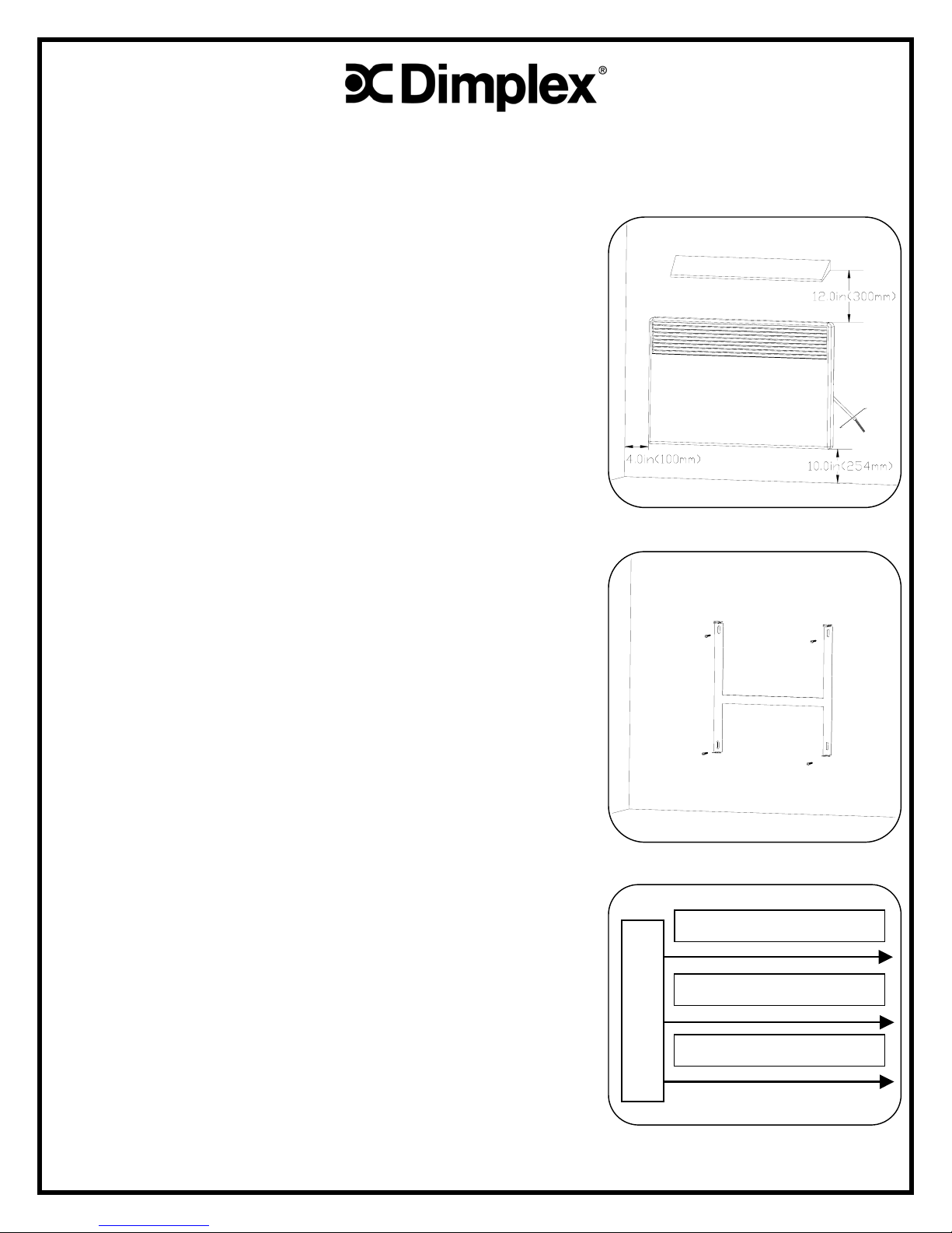
CAUTION
The minimum distances between the convector and any object in its
immediate vicinity must be observed to ensure correct operation (Figure 1).
1. Remove the tie wrap from electric cable.
2. Remove the mounting bracket from the rear of the convector casing by
squeezing the release tabs at the top of the bracket and pulling out of
the casing.
3. Place the bracket on the wall at the desired location, and mark the
mounting hole locations using the bracket as a template (Figure 2).
4. Secure the mounting bracket to the wall (Figure 2) using suitable
screws (not included).
5. Install a power receptacle box on the wall next to the convector
mounting bracket.
NOTE
The heater can be installed so the wall receptacle box can be hidden.
6. Feed the power supply wiring into the power receptacle box.
7. Install the convector onto the bottom tabs of the mounting bracket.
8. Snap the top of the convector casing onto the top tabs to secure the
convector to the bracket.
9. Connect the power supply wiring to the convector heater wiring
(Figure 3).
10. Install receptacle box cover.
NOTE
If the power receptacle box is located behind the heater the heater is to be
wire connected and then installed to the mounting bracket.
SAFETY PRECAUTIONS
WARNING
Secure convention heater to wall bracket before using.
1. Do not cover your heating unit in any way. The “DO NOT COVER”
warning tag is there to remind you that any materials covering the
units can catch fire.
2. Do not mask the heating unit with furniture or curtains, as this will
interfere with the operation of the convector.
3. Regularly clean and dust the inlet and outlet grid.
WHITE WIRE – POWER
BLACK WIRE – POWER
GREEN WIRE – GROUND
CONVECTOR HEATER
FIGURE 1
FIGURE 2
FIGURE 3
1
START UP
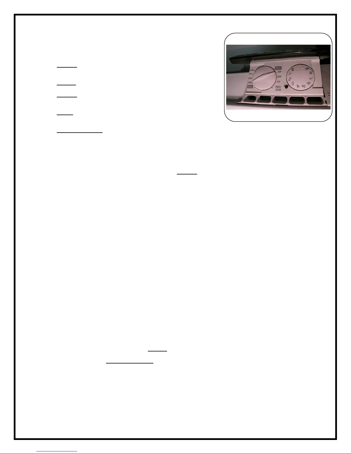
Description
The unit comprises of:
1. A thermostat control knob graduated MINI to MAXI, located in the
control box on the right side (Figure 4).
2. A mode selection knob, indicating the various operating modes
(Figure 3).
i. “PROG” position
The temperature will be the value set using the thermostat control
knob.
ii. “STOP”
position
The convector will be placed on standby mode.
iii. “COMF”
position
The temperature will be the value set using the thermostat control
knob.
iv. “ECO”
position
The temperature will be the value set using the thermostat control
knob less 3.5°C ±0.5°
v. “FREEZE GUARD”
position
FIGURE 4
The temperature will remain at around 7°C (45°F) regardless of the
setting selected on the thermostat control knob.
Setting the room temperature
For a perfect adjustment:
1. Place a thermometer at the center of the room 4ft (1.20m) off the ground (doors and windows closed)
2. Set the mode selection control knob to the comfort position “COMF”
.
3. Set the thermostat control knob to the maximum position.
4. Once the desired ambient temperature is reached, for example, when the thermometer indicates 20°C (68°F), slowly turn
back the thermostat control knob until the heating indicator light goes off. Once set, the thermostat will automatically
maintain this temperature in the room by switching the power supply to the unit on and off as required.
OPERATION
1. This unit is supplied with a manual reset temperature limit cutout, which will switch-off the heater should it overheat for
any reason.
2. If the cutout operates, it is the result of abnormal overheating. The source of the overheating must be found and
corrected.
3. After the source of the problem is found and corrected, the reset button can be pushed-in to re-energize the convector.
The reset button is located on the back of the convector casing, along the top edge.
REMOVING THE CONVECTOR
WARNING
Only qualified, approved personnel are authorized to work on our equipment. The convector must be disconnected from the
power supply before starting any work.
1. Before removing the unit from its mounting bracket ensure the power is disconnected.
2. Remove the power receptacle box cover from the wall.
3. Disconnect the convector from the power supply leads.
4. Remove the convector casing from the mounting brackets by squeezing the top release tabs.
5. Lift the convector off the bottom tabs.
PRACTICAL ADVICE
Economic Operation
1. Do not overheat your home by degrees above 20°C (68°F) as your power consumption could increase by 10%.
2. Cut off the power supply to your heating units (“STOP”
position) when you vent your rooms for any lengthy period of time.
3. Whenever your don’t use a room (guest room) or if you don’t use your home for any extended period of time (vacation),
set your heating units to the “FREEZE GUARD”
position.
Operating Precautions
1. To ensure regular operation of all the heating units in a single room, the thermostats must be set to the same
temperature.
2. Avoid operating a few heating units continuously to heat your entire home as this can result in disorders; unbalanced
heating, reduced comfort, excess consumption and micro-condensation.
3. Switch off the heating units in rooms where a chimney is being used to avoid wasted energy and to prevent circulating
smut and ashes through the convector and into the room.
The descriptions and characteristics are given for information only and are subject to modification with no prior notification
2
 Loading...