

Page 1
PARTS AND SERVICE MANUAL
FOR THE
ELECTRIC PATIO STOVE
Model EOS2006
Page 2

1
TABLE OF CONTENTS
OPERATION PAGE 2
PARTS DRAWING PAGE 4
PARTS LIST PAGE 5
WIRING DIAGRAM PAGE 6
LIGHT BULB REPLACEMENT PAGE 7
FLAME ROD AND MOTOR REPLACEMENT PAGE 8
CIRCUIT BOARD REPLACEMENT PAGE 9
SWITCH REPLACEMENT PAGE 10
POWER CORD REPLACEMENT PAGE 11
Page 3
2
EOS2006
OPERATION
To access the controls go to the back of the Stove.
A. MAIN ON/OFF SWITCH
The on/off switch supplies power to all unit functions (flame/towel warmer)
B. TOWEL WARMER ON/OFF SWITCH
The towel warmer on/off switch supplies power to the towel warmer. The main on/off
switch must be on to activate towel warmer switch.
NOTE: When the Towel Warmer is switched ON, the warmer will operate. The warmer will
not operate if the cooler insert is still in place within the unit.
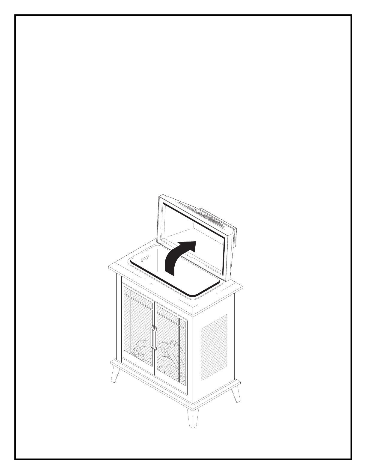
BEVERAGE COOLER
This stove has a convenient hidden beverage cooler located under the flip top lid. To use the
cooler ensure that cooler is inserted. Ice may be used. Place beverages in cooler insert and
surround with ice.
Page 4
3
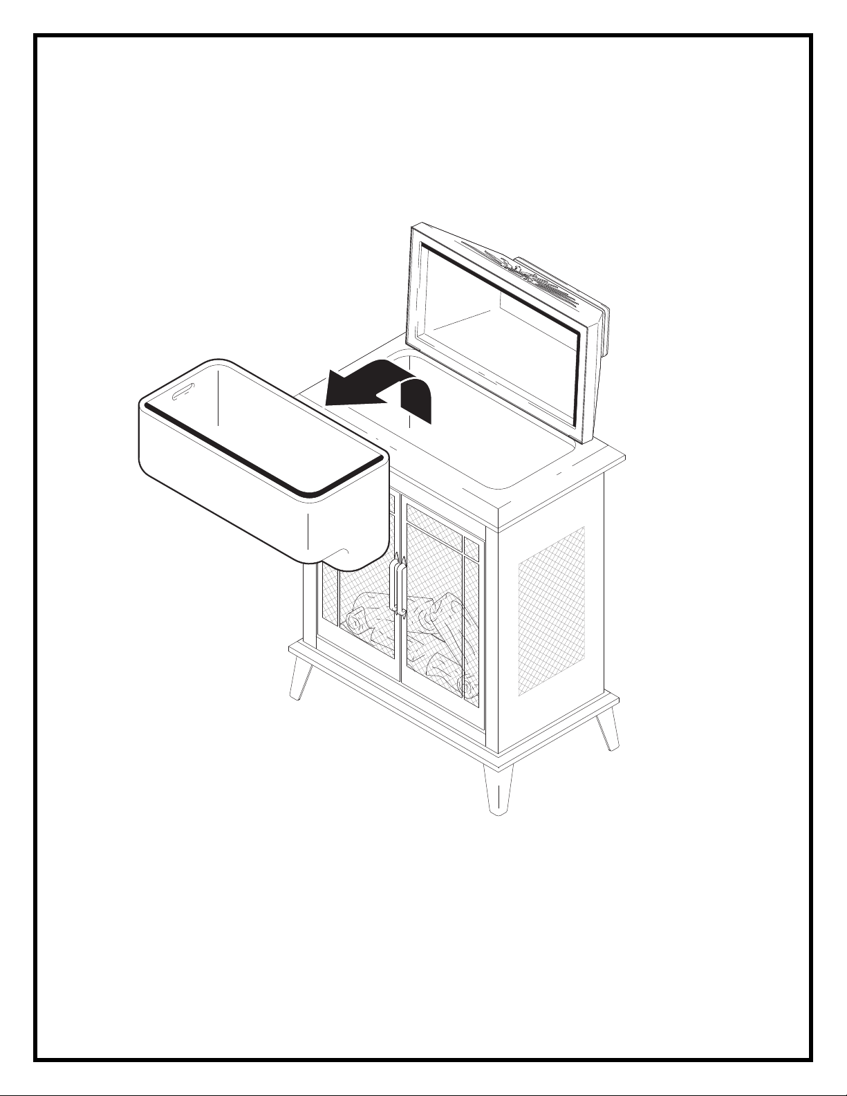
TOWEL WARMER
This unit has a convenient towel warmer built in. To operate the towel warmer remove cooler
insert, activate towel warmer switch (fig.2), and place dry towels in towel warmer
compartment. THIS IS NOT A TOWEL DRYER, DO NOT PLACE DAMP OR WET
TOWELS IN COMPARTMENT
Page 5

4
11
2
8
7
9
10
6
3
5
4
1
Page 6

5
EOS2006
REPLACEMENT PARTS
OUTDOOR ELECTRIC STOVE
CATALOGUE NO. EOS2006
PART NO. 6903510159
REPLACEMENT PART
1. MOTOR, ASSEMBLY 2000220100RP
2. CIRCUIT BOARD 3000570100RP
3. MIRROR 5900820100RP
4. FLAME ROD 5900340100RP
5. BUSHING 8500000400RP
6. LOGSET 0438270100RP
7. POWER CORD 4100170200RP
8. SWITCH, SPLASHPROOF 2800130200RP
9. TERMINAL BLOCK 4000070100RP
10. CAPACITOR 3200030100RP
11. COOLER ASSEMBLY 0478060100RP
Page 7

6
WIRING DIAGRAM
Page 8

7
EOS2006
LIGHT BULB REPLACEMENT
Allow at least 5 minutes for light bulbs to cool off before touching bulbs to avoid accidental
burning of skin.
Light bulbs need to be replaced when you notice a dark section of the flame or when the
clarity and detail of the log exterior disappears. There are three bulbs under the log set
which generate the flames and embers.
HELPFUL HINTS
It is a good idea to replace all light bulbs at one time if they are close to the end of their rated
life. Group replacement will reduce the number of times you need to open the unit to replace
light bulbs.
LIGHT BULB REPLACEMENT
1. Open door by pulling the handles.
2. Remove the screw from the logset located in the center of the emberbed and remove
the logset from the unit.
3. Locate and examine the bulbs to determine which bulb(s) required replacement.
4. Locate and remove the light bulb(s).
5. Insert new bulb(s).
6. Install the logset into the unit, pushing firmly against the glass. Replace the logset
retaining screw into the ember bed.
7. Close the doors.
LIGHT BULB REQUIREMENTS
Quantity of 3 clear chandelier or candelabra bulbs with an E-12 (small) socket base,
60 watt rating.
Page 9

8
EOS2006
If unit was operating prior to servicing allow at least 10 minutes for light bulbs and heating
element to cool off to avoid accidental burning of skin.
Disconnect power before attempting any maintenance or cleaning to reduce the risk of
electric shock or damage to persons.
FLAME ROD AND MOTOR REPLACEMENT
1. Open door by pulling the handles.
2. Remove the screw from the logset located in the center of the emberbed and remove the
logset from the unit.
1. While holding the mirror to prevent it from moving, remove the 2 mirror retaining bracket
screws. Carefully remove the mirror and store in a safe place to prevent damage.
2. Remove the 3 screws securing rear reflector to the unit.
3. Remove the reflector rod from the flame motor by pulling the end of the rod to the left and
carefully remove flame rod from rubber sleeve.
4. Remove the 2 screws securing the flame motor to the flame motor bracket
5. Disconnect motor wiring connections from circuit board.
6. Discard the old motor.
7. Reassemble in the reverse order as above.
Page 10

9
EOS2006
If unit was operating prior to servicing allow at least 10 minutes for light bulbs and heating
element to cool off to avoid accidental burning of skin.
Disconnect power before attempting any maintenance or cleaning to reduce the risk of
electric shock or damage to persons.
CIRCUIT BOARD REPLACEMENT
1. Open door by pulling the handles.
2. Remove the screw from the logset located in the center of the emberbed and remove the
logset from the unit
3. While holding the mirror to prevent it from moving, remove the 2 mirror retaining bracket
screws. Carefully remove the mirror and store in a safe place to prevent damage.
4. Remove the 3 screws securing rear reflector to the unit.
5. Locate the circuit board on the underside of the rear reflector bracket.
6. Remove wiring connections from circuit board noting their original locations.
7. From the underside of the circuit board, break off the 4 mounting studs by grasping with
pliers and twisting on the protruding part of the stud, push the remainder of the studs out
through the top panel.
8. NOTE: New mounting studs are supplied with the replacement circuit board
9. Reassemble in the reverse order as above.
Page 11

10
EOS2006
WARMER
MAIN
If unit was operating prior to servicing allow at least 10 minutes for light bulbs and heating
element to cool off to avoid accidental burning of skin.
Disconnect power before attempting any maintenance or cleaning to reduce the risk of
electric shock or damage to persons.
SWITCH REPLACEMENT
1. Open door by pulling the handles.
2. Remove the screw from the logset located in the center of the emberbed and remove the
logset from the unit
3. While holding the mirror to prevent it from moving, remove the 2 mirror retaining bracket
screws. Carefully remove the mirror and store in a safe place to prevent damage.
4. Remove the 3 screws securing rear reflector to the unit.
5. Locate the switches on the back wall of the unit.
6. Remove wiring connections from the switches noting their original locations.
7. Squeeze the tabs on the top and bottom of the switch and push out through the back of
the unit.
8. Connect all of the wiring connections in their original locations.
9. Reassemble in the reverse order as above.
Page 12

11
EOS2006
WARMER
MAIN
If unit was operating prior to servicing allow at least 10 minutes for light bulbs and heating
element to cool off to avoid accidental burning of skin.
Disconnect power before attempting any maintenance or cleaning to reduce the risk of
electric shock or damage to persons.
POWER CORD REPLACEMENT
1. Open door by pulling the handles.
2. Remove the screw from the logset located in the center of the emberbed and remove the
logset from the unit
3. While holding the mirror to prevent it from moving, remove the 2 mirror retaining bracket
screws. Carefully remove the mirror and store in a safe place to prevent damage.
4. Remove the 3 screws securing rear reflector to the unit.
5. Remove the power cord wiring connections from the terminal block.
6. Remove the power cord ground wire from the ground terminal.
7. With needle nose pliers grasp the power cord strain relief grommet from inside the rear
panel and push while twisting to remove.
8. Pull the power cord out through the hole in the rear cover.
9. Install the new cord set through the hole in the rear cover by placing the strain relief over
the cord, hold the strain relief with pliers and slide into mounting hole.
10. Connect all of the wiring connections in their original locations.
11. Reassemble in the reverse order as above.
 Loading...