

Dimplex Pro Engine series, ENG68-400 E, ENG56-400 E, ENG56-600 E Operating Instructions Manual
Page 1

Dimplex Pro Engine Range
Models: ENG56-400 E, ENG68-400 E, ENG56-600 E
These instructions should be read carefully and
retained for future use. Note also the information
presented on the appliance.
OPERATING
INSTRUCTION MANUAL
08/53883/0 ISSUE 2 OCN 10949
EN: This product is only suitable for well insulated rooms or occasional use. DE: Dieses Produkt ist nur für gut isolierte Bereiche oder
gelegentliche Verwendung geeignet. FR: Ce produit convient uniquement à des endroits bien isolés ou pour un usage occasionnel.
IT: Questo prodotto è adatto solo per spazi ben isolati o per uso occasionale. ES: Este producto sólo es adecuado para espacios
bien aislados o un uso ocasional. NL: Dit product is uitsluitend geschikt voor goed geïsoleerde ruimten of voor sporadisch gebruik.
PL: Produkt ten jest odpowiedni wyłącznie do dobrze odizolowanych miejsc lub do okazjonalnego użytku. NO: Dette produktet
egner seg kun for godt isolerte rom eller sporadisk bruk. RO: Acest produs este adecvat exclusiv spaţiilor bine ventilate sau utilizării
ocazionale. CZ: Tento výrobek je vhodný pouze do dobře izolovaných prostor nebo k příležitostnému použití. DK: Dette produkt
er kun egnet til velisolerede rum eller lejlighedsvis brug. PT: Este produto somente é adequado para espaços bem isolados ou
uso ocasional. SE: Denna produkt är endast avsedd för välisolerade utrymmen eller tillfällig användning. FI: Tämä tuote soveltuu
ainoastaan hyvin eristettyihin tiloihin tai satunnaiseen käyttöön. SK: Tento výrobok je vhodný len pre dobre izolované priestory alebo
na občasné použitie. SI: Ta izdelek je primeren le za dobro izolirane prostore ali za občasno uporabo. HR: Ovaj proizvod je pogodan
samo za dobro izolirane prostore ili povremenu upotrebu. HU: Ez a termék csak jól szigetelt terekhez vagy eseti használatra alkalmas
The product complies with the European Safety Standards EN60335-2-30 and the European Standard Electromagnetic
Compatibility (EMC) EN55014, EN60555-2 and EN60555-3. These cover the essential requirements of EEC Directives
2014/30/EU and 2014/35/EU
Page 2

2
CAUTION: FAILURE TO FOLLOW THESE INSTRUCTIONS MAY CAUSE INJURY AND/OR
DAMAGE AND MAY INVALIDATE YOUR GUARANTEE
Important Safety Advice
When using electrical appliances, basic precautions should always be followed to reduce the
risk of fire, electrical shock and injury to persons, including the following:
If the appliance is damaged, check with the supplier before installation and operation.
Do not use outdoors.
Do not use in the immediate surroundings of a bath, shower or swimming pool.
Do not locate the appliance immediately below a fixed socket outlet or connection box.
Caution: Some parts of this product can become very hot and cause burns. Particular attention
has to be given where children and vulnerable people are present. This instruction can be found
at www.dimplex.co.uk
Warning: This heater must not be used for anything other than normal domestic household
purposes in the country where it was purchased from a recognised commercial retailer.
This appliance can be used by children aged from 8 years and above and persons with reduced
physical, sensory or mental capabilities or lack of experience and knowledge if they have been
given supervision or instruction concerning use of the appliance in a safe way and understand
the hazards involved. Children shall not play with the appliance. Cleaning and user maintenance
shall not be made by Children without supervision.
Children of less than 3 years should be kept away unless continuously supervised. Children
aged from 3 years and less than 8 years shall only switch on/off the appliance provided that it
has been placed or installed in its intended normal operating position and they have been given
supervision or instruction concerning use of the appliance in a safe way and understanding the
hazards involved. Children aged from 3 years and less than 8 years shall not plug in, regulate
and clean the appliance or perform user maintenance.
Warning: This appliance must be earthed.
The use of an extension lead or multi-plug adaptor is not advised when connecting this product
to the mains. Connection through these devices could lead to a risk of overloading, overheating
and even fire at the extension lead or adaptor due to inadequate connection quality.
This heater must be used on an ~alternating current supply (~) only and the voltage marked on
the heater must correspond to the supply voltage.
Do not use this appliance in series with a thermal control, a program controller, a timer or any
other device that switches on the heat automatically, since a fire risk exists when the appliance
is accidentally covered or displaced.
DO NOT use the heater on deep pile carpets or the long hair type of rugs, or less than 750mm
(30”) away from any overhanging surface. Keep combustible materials such as drapes and
other furnishings clear from the front, sides and rear of the heater. Do not use heater to dry your
laundry.
In the event of a fault unplug the appliance. Unplug the appliance when not required for long
periods.
The appliance must be positioned so that the plug is accessible. If the supply cord is damaged
it must be replaced by the manufacturer or service agent or a similarly qualified person in order
to avoid a hazard. Keep the supply cord away from the front of the appliance.
Page 3

3
Warning: In order to avoid overheating, do not cover the appliance. Do not place material or
garments on the appliance, or obstruct the air circulation around the appliance, for instance by
curtains or furniture, as this could cause overheating and a fire risk.
The appliance carries a DO NOT COVER warning
Warning: In order to avoid a hazard due to inadvertent resetting of the thermal cut-out, this
appliance must not be supplied through an external switching device, such as a timer, or
connected to a circuit that is regularly switched on and off by the utility.
Thank you for choosing a Dimplex electric fire
Dimplex PRO Chassis
Models: Engine 56 - 400 E / Engine 68 - 400 E / Engine 56 - 600 E
Only use filtered water in this appliance.
Always ensure that the appliance is sitting on a level surface.
Although this heater complies with safety standards, we do not recommend its use on deep pile carpets or
on long hair type of rugs.
Please note: Used in an environment where background noise is very low, it may be possible to hear a sound
which is related to the operation of the flame effect. This is normal and should not be a cause for concern.
If this product experiences a power surge for whatever reason the product may cut-out. This is a normal safety
feature and the product will resume operation after 30 seconds.
Once installed, never move this appliance or lay on its back, without draining the water from sump and water
tank.
If you intend not using the appliance for longer than 2 weeks, drain the water from sump and water tank and
dry the sump.
The water tank, sump, sump lid, tank cap and air filters must be cleaned once every two weeks, particularly
in hard water areas.
The appliance should never be operated if the lamps are not working.
The lamps should be regularly inspected as described under ‘Maintenance’ and ‘Changing lamps’.
The sump and the water tank in this product are treated with a biocidal product, Silver Biocide. This conforms
with the latest relevant ISO standard.
Technical Information
Model No: ENG56-400 E, ENG68-400 E, ENG56-600 E
with electronic room temperature control.
General Information
Heat Output 230V 240V
Nominal Heat Output
P
Nom
1.8 2.0 kW
Minimum Heat Output
P
min
0.9 1.0 kW
Maximum Continuous Heat Output
P
max
1.8 2.0 kW
Auxiliary Electricity Consumption
In Standby Mode
P
Nom
0.45 0.48 W
Page 4

4
Installation Instructions
This section describes how to set up your fire.
BEFORE YOU START
1. Ensure that all packing items are removed (read any warning labels carefully) and retain all packing for
possible future use e.g. in the event of moving house or returning the appliance to your supplier.
2. Before connecting the appliance, check that the supply voltage is the same as that stated on the heater.
Installation into a Fireplace Mantle
● When installing this appliance into a fireplace mantle please ensure that you choose a mantle suitable for
your appliance (Fig 17). There is to be an air vent at the front of the fireplace mantle of at least 100cm2.
It is essential to ensure that air can circulate into the appliance – otherwise the Opti-myst flame effect will
not operate correctly. This pathway for air must not be obstructed
● Remove the 4 spacing brackets on the front of the appliance (Fig 18)
● Slide the appliance into the fireplace mantle fully from the back ensuring that it is sitting in the center of
the mantle. Using suitable screws (not supplied) screw fix the appliance in place (Fig 19)
● Be sure to position the fireplace within 1m of a power outlet (Fig 20)
Installation into a wall or recess cavity
● Note the product dimensions in Fig 1 and build a suitable structure for the appliance to fit into within 1m
of a power outlet (Fig21). Using suitable screws (not supplied) screw fix the appliance in place
● Note the venting slots in the appliance. There are located at the front base and under the appliance
● Build the wall up against the appliance using the spacing brackets as a guide.
● There is to be an air vent at the front of the structure of at least 88cm2. It is essential to ensure that air can
circulate into the appliance – otherwise the Opti-myst flame effect will not operate correctly. This pathway
for air must not be obstructed. For examples of air vents in a wall or recess cavity see Fig 22 and Fig 23.
PLEASE ENSURE CHILDREN DO NOT CLIMB, HANG OR STAND ON THIS PRODUCT.
WARNING: THE APPLIANCE IS PROVIDED WITH A TIPPING RESTRAINT, THIS RESTRAINT IS NOT A
SUBSTITUTE FOR PROPER ADULT SUPERVISION. THIS RESTRAINT MAY PROVIDE PROTECTION
AGAINST TIPPING FURNITURE. DO NOT ALLOW CHILDREN TO CLIMB ON FURNITURE. FAILURE TO
DETACH THIS RESTRAINT BEFORE MOVING FURNITURE MAY RESULT IN INJURY AND DAMAGE.
This product is provided with a ‘Tipping Restraint Kit’ as shown in Fig 1, to prevent the product accidentally
tipping over. Fitting Instructions are supplied with this kit please follow these instructions carefully.
Connecting the Transducer Unit + Lamps
1. Release the two red tabs by turning them by 90 degrees (Fig 2)
2. Lift out the Sump Nozzle (Fig 3)
3. Insert lamps into lamp holders (Fig 4), carefully locating the pins into the holes (Fig 4a)
4. Push lamps firmly into place
5. Place the Transducer Unit into the sump and join the cable to the connector on the sump (Fig 5)
6. To ensure that the Transducer Unit is correctly placed in the sump, the tab on the Transducer Unit should
be lined up with the moulded recess in the sump (Fig 5a).
7. Ensure that the cable is not placed above the disc on the Transducer Unit (Fig 5b). To prevent the cable
becoming pinched between the nozzle and the sump, place the cable in the slot in the wall of the sump.
8. Replace the Sump Nozzle and secure it by turning the two red tabs by 90 degrees (Fig 6)
Page 5

5
Filling the Water Tank
9. Place Water Tank in sink and remove cap (turn anti-clockwise to open) (Fig 7)
10. Fill Water Tank with filtered tap water only. This is necessary to prolong the life of the flame and smoke
producing unit. The water should be filtered through a conventional domestic water filter unit and the filter
should be replaced regularly. Distilled water must not be used.
11. Screw the cap back on – do not overtighten.
12. Place the Water Tank in the Sump, with the tank cap facing down and the flat side of the tank facing
outward (Fig 8)
Assembling the fire
13. Place the Fuelbed on top of the Water Tank and Mist Nozzle (Fig 9)
Operating The Product
WARNING: FAILURE TO FOLLOW THESE OPERATING INSTRUCTIONS MAY RESULT IN INJURY AND/
OR DAMAGE.
MANUAL CONTROLS
The manual controls are located beneath the hinged flap. (Fig.10 for Manual Control lay out)
Switch ‘A’:- Controls the electricity supply to the Fire.
Note: This switch must be in the ‘ON’ ( I ) position for the Fire to operate either with or without heat.
Switch ‘B’:- Press once to turn on the flame eect. This will be indicated by an audible beep. Although
the main lights operate immediately it will take a further 30 seconds before the flame eect starts.
Press to put fire in to standby mode. This will be indicated by one beep.
REMOTE CONTROL
The remote control is packed with 2 AA batteries in a bag. Lift o the battery cover on the back of the
remote control and insert the batteries taking note of the polarity.
Switching on the appliance
Press and hold the ENTER button for 3 seconds to activate the remote control. FIRE will be displayed and
ON will be blinking. Press ENTER to swtich on the appliance. To turn o the appliance press MENU so that
FIRE is blinking, press ENTER twice.
Adjust the Flame Setting
With the remote control activated press MENU once. FIRE will be blinking on the display. Press ENTER.
The current flame setting will be displayed F1-F6. Press the UP and DOWN buttons to adjust the setting.
After you have selected your flame setting press BACK twice to exit the menu and return to the home
screen.
Switching on the Heat
With the remote control activated press MENU once. FIRE will be blinking on the display. Press ADV once,
HEAT will be blinking. Press ENTER. The current heat setting will be displayed OFF LO HI. Press the UP
and DOWN buttons to adjust the setting. After you have selected your flame setting press ENTER
Setting the Thermostat
The temperature shown on the display is the room temperature set point. This is the temperature that the
heater will maintain during the heating periods. If the room temperature is above this temperature then the
Page 6
6
Modes of Remote Operation
User Timer: Provides greatest flexibility to the user. Four times slots are available throughout the day and
these can be customised for each day of the week. See “How to adjust the timer modes” for instructions on
adjusting these from the factory default time periods & temperatures.
Manual Mode: This mode heats the room to the temperature you have set the remote control to.
Frost Protection: This mode will maintain a room temperature to 7ºC. This mode should be used to provide
protection against frost as indicated by the frost icon.
Choosing and Setting a Mode
User Timer - To re-programme the factory default Timer Modes:
Press Menu Button
Press ^ once to the schedule Icon is blinking. Press Enter
Press ^ Twice then press Enter
*Days of the weeks are now displayed at the top of the screen*
heater will not operate. The heater leaves the factory with this temperature set at 15ºC which represents a
typical comfortable room temperature. If you require a dierent room temperature then press either up or
down on the home screen until the display shows the temperature you require.
Thermal Safety Cut-out
A thermal safety cut-out is incorporated in the fan heater to prevent damage due to overheating. This can
happen if the heat outlet was restricted in any way. If the cut-out operates, unplug the heater from the
socket outlet and allow approximately 10 minutes before reconnecting. Before switching the heater back
on remove any obstruction that may be restricting the heat outlet, then continue normal operation.
CAUTION: In order to avoid a hazard due to inadvertent resetting of the thermal cutout, this appliance
must not be supplied through an external switching device, such as a timer, or connected to a switch that is
regularly switched on and off by the utility.
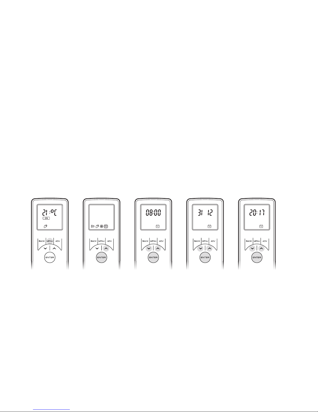
Setting the Date and Time
To set the date and time on the heater;
Press the Menu button
Press ^ button 4 times
Press Enter when the Date & Time icon is blinking
Press Enter to set Time
Press v and ^ to set the Hour, press Enter
Press v and ^ to set the Minutes, press Enter to confirm the time
Press v and ^ to set the Day, press Enter
Press v and ^ to set the Month, press Enter
Press v and ^ to set the Year, press Enter to confirm the date
Page 7

7
Day 1 = Monday
Day 2 = Tuesday
Day 3 = Wednesday
Day 4 = Thursday
Day 5 = Friday
Day 6 = Saturday
Day 7 = Sunday
Press Enter to Modify Day 1 or Press ^ to navigate to the desired day and Press Enter to Select
P1 will be displayed on screen
Press Enter to select P1, to navigate to P2, P3 or P4 press ^ and press Enter to select
ON will be highlighted, press Enter to set the on Time
Press v or ^ to adjust the on Hour time, press Enter to Confirm
Press v or ^ to adjust the on Minute time, press Enter to Confirm
Press v or ^ to adjust the Temperature setting, press Enter to Confirm
Press v or ^ to adjust the off Hour time, press Enter to Confirm
Press v or ^ to adjust the off Minute time, press Enter to Confirm
Press Enter to modify Programme P2, follow steps 5-12, Press ^ to skip to P3
Press Enter to modify Programme P3, follow steps 5-12, Press ^ to Skip to P4
Press Enter to modify Programme P4, follow steps 5-12
To copy newly programmed P1-P4 heating programmes to other days press the Enter button.
Copy will be displayed on screen
To copy to the next day in sequence, press ^ button. To deselect the next day in sequence press
Enter button.
The days of the week that are selected will be displayed at the top of the screen. The days that
have been deselected will not be visible (see Diagrams).
Press Enter to confirm, backlight will flash and return to home screen.
Page 8

8
Getting the Desired Flame Effect
Using the remote control press MENU, FIRE on the display will be flashing, press ENTER. The current setting
will be displayed. Press ^ or v to toggle between F1 and F6. F1 being the lowest setting and F6 being the
highest setting.
Generally the flames appear more realistic when the flame control is turned down.
Give the flame generator time to react to changes you may make.
The fire will use less water if the flame effect is set to a lower level.
Do not tilt or move the fire while there is water in the tank or sump.
Make sure that the fire is on a level floor.
Customising the display
The maximum temperature set point on the product is 32ºC You have the option to reduce this set point. You
can also change ºC to ºF
Press the Menu button.
Press the ADV button twice - SP will be blinking.
Press Enter to confirm.
Press v or ^ to choose between ºC and ºF.
Press Enter to confirm.
Press v or ^ to choose your maximum temperature set point.
Press Enter to confirm.
Press BACK three times to return to the home screen.
Adaptive Start
The built-in electronics in this appliance hava a learning function with regards to how long it takes to heat up
a room. Having learnt how quickly it can heat up your room, the appliance is able to turn on at just the right
time in order to get the room up to a comfortable temperature when you want it. For example, if you get up at
7am, you would normally have to guess when to turn the heating on in order for it to pre-heat the room in time.
Manual Mode - To choose a constant heat mode. This mode ignores the User Timer and maintains the
displayed temperature.
• Press Menu Button
• Press ^ twice to highlight the Hand icon
• Press Enter to Confirm
• Use v and ^ to adjust to the desired temperature
Frost protect - Frost protect mode maintains a room temperature of 7ºC throughout a 24 hour period. This
mode should be used to provide protection against frost as indicated by the Frost icon.
• Press the Menu button
• Press ^ three times to highlight the snowflake icon
• Press Enter to confirm
• Press v or ^ to exit this mode and enter manual mode.
Page 9

9
1
Display Screen
2
‘Menu’ Button
3
‘Back’ Button
4
‘Advance’ Button
5
‘Up and Down’ Arrows
6
‘Enter’ Button
1
2
6
3
Remote Control
4
5
Depending on how cold it is outside, this could mean the room is still cold when you have to get out of bed, or
mean that its been warm for half an hour before it needed to be. Adaptive Start means that if you select 21ºC
at 7am, the heater will turn on exactly when it needs to in order to meet this target, running for shorter periods
of time when the weather is mild, and ensuring the room is nice and warm in the winter.
The Adaptive Start function will automatically activate when you use the Timer Mode.
Maintenance
GENERAL TIPS
Only use filtered tap water in this appliance.
Always ensure that the appliance is sitting on a level surface.
If you intend not using the appliance for longer than 2 weeks, remove and empty the sump and water tank.
Once installed, never move this appliance or lay on its back, without draining the water from sump and water
tank.
The appliance should never be operated if the lamps are not working.
The lamps should be regularly inspected as described under ‘Changing lamps’.
FILLING THE WATER TANK
When the water tank is empty, the flame and smoke effect shuts off and you will hear 2 audible beeps, follow
these steps.
1. Press Switch ‘A’ to (0) (Fig.10)
2. Gently lift out the fuelbed and carefully set aside.
Page 10

10
3. Remove the water tank by lifting upwards and outwards.
4. Place the water tank in sink and remove cap, Anti-clockwise to open. (Fig 7)
5. Fill tank with filtered tap water only. This is necessary to prolong the life of the flame and smoke producing
unit.
6. The water should be filtered through a conventional domestic water filter unit and the filter should be
replaced regularly.
7. Screw the cap back on, do not over tighten.
8. Return the tank to the sump, with the tank cap facing down and the flat side of the tank facing outward
(Fig 8)
9. Gently place the fuelbed back into position. (Fig 9)
10. Press Switch ‘A’ to ‘ON’ (I) position (Fig.10)
CHANGING LAMPS
If the flame and smoke effect appears grey or colourless it may be that one or more lamps have failed.
You can check for lamp failure as follows.
1. Leaving the flame effect on, lift out the fuelbed and water tank.
2. It should be possible to view the lamps with the nozzle in place and observe which one needs to be
changed.
3. Put Switch ‘A’ in the ‘OFF’ position, and unplug the fire from the mains.
4. Leave the appliance for 20 minutes to allow the lamps to cool down before removing them.
5. Remove the sump as described in the Cleaning Section.
6. Remove the defective lamp, by gently lifting vertically and disengaging the pins from the lamp holder,
(Fig.4 and 4a).
7. Replace with an OPTIMYST, 12V, 45W, Gu5.3 base, 8º beam angle, coloured lamp. (Purchased from
www.dimplex.co.uk/spares)
8. Carefully insert the two pins of the new lamp into the two holes in the lamp holder. Push firmly in place.
(Fig.4 and 4a).
9. Replace the sump, nozzle, water tank and fuelbed.
CLEANING
Warning – Always press Switch ‘A’ to the ‘OFF’ (0) position (Fig.10) and disconnect from the power supply
before cleaning the fire.
We recommend cleaning the following components once every 2 weeks, particularly in hard water areas:Water Tank, Sump, Nozzle, Tank cap and seal, Air filter.
For general cleaning use a soft clean duster – never use abrasive cleaners.
To remove any accumulation of dust or fluff the soft brush attachment of a vacuum cleaner should occasionally
be used to clean the outlet grille of the fan heater.
Water tank
1. Remove water tank, as described earlier, put into sink and empty water.
2. Using the supplied brush gently rub the inside surfaces of the cap paying particular attention to the rubber
ring in the outer groove and the centre rubber seal.
3. Put a small quantity of washing up liquid into the tank, refit the cap and shake well, rinse out until all traces
of washing up liquid are gone.
4. Refill with filtered tap water only, replace the cap, do not overtighten.
Sump
1. Press Switch ‘A’ to the ‘OFF’ (0) position
2. Gently lift out the fuelbed and place carefully on the ground.
3. Remove the water tank by lifting upwards.
Page 11

11
Additional Information
After Sales Service
Your product is guaranteed for one year from the date of purchase. Within this period, we undertake to
repair or exchange this product free of charge (excluding transducer discs & subject to availability) provided
it has been installed and operated in accordance with these instructions. Your rights under this guarantee
are additional to your statutory rights, which in turn are not affected by this guarantee.
The transducer is a consumable item and may need to be replaced through time, depending on its usage.
Replacement transducers can be purchased from your supplier.
The transducer has a 12 month warranty period.
CAUTION: Do not use if the heater’s mains power lead is damaged. Such use may cause a hazard. If
damaged, the mains power lead must be replaced by the manufacturer or its authorised dealer.
Recycling
For electrical products sold within the European Community - At the end of the electrical products
useful life it not be disposed of with household waste. Please recycle where facilities exist. Check
with your Local Authority or retailer for recycling advice in your country.
Patent / Patent Application
Products within the Optimyst range are protected by one or more of the following patents and patent
applications:
Great Britain GB2460259B, GB2475794B, GB2418014, EP2029941, GB2436212, GB2402206B
United States US8413358, US8136276, US7967690, US8574086
Russia RU2434181
European EP2029941, EP2315976, EP1787063 (A1), EP2388527
China CN101883953A, CN102105746A, CN101057105 (A), CN101438104
Australia AU2009248743A1, AU2007224634
Canada CA2725214, CA2579444, CA2645939
4. Disconnect the electrical connector, located on the right side of the sump. (Fig.5) .
5. Release the right sump locking tabs by turning 90º. This allows the sump to be lifted completely from its
location. (Fig. 11)
6. Gently lift up the sump, taking care to keep level so as not to spill any water. Sit the assembly in the sink.
7. Release the left sump locking tabs by turning 90º, then lift off the Nozzle. (Fig.3)
8. Lift out the transducer and carefully tilt, as shown, so that the liquid drains out of the sump. (Fig.13)
9. Put a small amount of washing up liquid into the sump, and using the supplied brush, gently clean all
surfaces in the sump and gently clean the transducer including the metal discs located in the top grooved
surface. (Fig.14)
10. When cleaned, thoroughly rinse the sump with clean water to remove all traces of washing up liquid.
11. Clean the Nozzle with the brush and flush out thoroughly with water. (Fig.15)
12. Reverse the above steps to reassemble.
Air filter
1. Gently lift out the fuelbed and place carefully on the ground.
2. Gently slide the air filter upwards out of its plastic holder. (Fig.16)
3. Gently rinse with water in the sink and dry with fabric towel before returning.
4. Replace the filter making sure that the coarse black filter is facing the front of the fire.
Page 12

12
South Africa ZA2008/08702
Mexico MX2008011712
South Korea KR101364191
Japan JP5281417, JP5496291
Brazil BRP10708894
India 4122/KOLNP/2008
New Zealand NZ571900
Symptom Cause Corrective Action
The flame effect will
not start.
Mains plug is not plugged in.
Low water level.
Low voltage connector not connected
properly. (Fig.5)
The Transducer Unit is not sitting
correctly in the sump
Check plug is connected to wall socket
correctly.
Check that the water tank is full and
there is water in the sump.
Check that the connector is inserted
correctly. (Fig.5)
Ensure the Transducer in sitting down
into the moulded recess in the sump
The flame effect is
too low.
Flame effect setting is set too low.
The Metal Disc in the transducer might
be dirty (Fig.14)
The wire from the Transducer Unit is
sitting over the metal disc
Increase the level of fire with the remote
control
Clean the Metal Disc with soft brush
supplied. (Fig.14) See ‘Maintenance.’ for
a step by step procedure.
Direct the wire to the back of the sump
and make sure it sits into the side slot
exiting the sump.
Unpleasant smell
when unit is used.
Dirty or stale water.
Using unfiltered tap water.
Clean the unit as described under
maintenance.
Use only filtered tap water.
The flame effect has
too much smoke.
Flame effect setting is too high. Decrease the level of the fire with the
remote control
Main lamps are not
working and there
are no flames or
smoke.
There is no water in the water tank Follow instructions under
Maintenance, ‘Filling the water tank’.
Check the plug is connected to the wall
socket correctly and that Switch ‘A’ Fig.
10 is in the ‘ON’ ( I ) position.
Troubleshooting
Page 13

13
Fig. 4
Fig. 4a
Fig. 2 Fig. 3
Fig. 1
X
W
255
168
Y
H
MODEL ‘H’ ‘W’ ‘X’ ‘Y’
ENG56-400 700mm 490mm 413mm 395mm
ENG68-400 823mm 490mm 413mm 517mm
ENG56-600 700mm 646mm 569mm 395mm
Page 14

14
Fig. 5 Fig. 5a
Fig. 5b Fig. 6
Fig. 7 Fig. 8
Page 15

15
Fig. 10
Fig. 11 Fig. 12
Fig. 13 Fig. 14
Fig. 9
Page 16

16
Fig. 15
Fig. 16
Page 17

17
x8
>100cm
2
ENG56-400 A=440mm B=386mm
ENG68-400 A=440mm B=509mm
ENG56-600 A=566mm B=386mm
1m
Fig. 17 Fig. 18
Fig. 19
Fig. 20
Page 18

18
?
?
>88cm
2
?
?
2
?
?
2
1m
B
C
A
>100cm
2
>100cm
2
>100cm
2
Fig. 21
Fig. 22 Fig. 23
X
Page 19

19
Page 20

Opti-myst is a trade mark of GDC Group Ltd.
DIMPLEX
MILLBROOK HOUSE
GRANGE DRIVE
HEDGE END
SOUTHAMPTON
SO30 2DF
TEL: 0844 879 3588
FAX: 0844 879 3583
WEBSITE: www.dimplex.co.uk
Republic of Ireland Tel. 01 8424833
c
GDC Group Ltd,
All rights reserved. Material contained in this publication may not be reproduced in whole or in part, without prior permission in
writing of Dimplex.
A division of GDC Group Ltd,
 Loading...