

Dimplex EF 12/20, EF 12/20 TI, EF 12/20 TID, EF 12/10 Installation And Operating Instructions Manual
Page 1
D
EN
F
I
GR
PL
CZ
HU
BG
Montage- und Gebrauchsanweisung 2
Installation and Operating Instructions 4
Instructions de montage et d’utilisation 6
Istruzioni d'uso e di montaggio 8
Οδηγίες τοποθέτησης και χρήσης 10
Instrukcja montażu i obsługi 12
Návod k montáži a použití 14
Szerelési és használati útmutató 16
Инструкция за монтаж и употреба 18
EF 12/20
EF 12/20 TI
EF 12/20 TID
EF 12/10
E
F
1
2
/
2
0
T
I
Schnellheizer
Fan Heater
D EN F I GR
PL CZ HU BG
INDEF12WRG ISSUE 0
Page 2

2
Montage- und Gebrauchsanweisung
EF 12/20, EF 12/20 TI, EF 12/20 TID, EF 12/10
1. Wichtige Hinweise
Bewahren Sie diese Anweisung sorgfältig auf und geben Sie
diese gegebenenfalls an Nachbesitzer weiter.
• Das Gerät ist nur zur Raumlufterwärmung innerhalb geschlossener Räume geeignet.
• Reparaturen und Eingriffe in das Gerät dürfen nur von einem Fachmann ausgeführt werden.
• Im Fehlerfall Gerät vom Netz trennen (Gerätestecker ziehen
oder Sicherung ausschalten).
• Heizgerät nicht abdecken, Brandgefahr!
Das nebenstehende Symbol ist am Heizgerät angebracht und bedeutet, dass das Heizgerät nicht
abgedeckt werden darf.
• Mindestabstände einhalten.
• Vorsicht! Außenflächen und besonders das Luftaustrittsgitter werden bei Betrieb heiß.
• Heizgerät nicht durch Kinder oder andere Personen betreiben, die nicht in der Lage sind, das Gerät sicher zu benutzen. Sicherstellen, dass Kinder nicht am Gerät spielen.
• Vorsicht! Nach automatischem Einschalten des Gerätes
können Gefahren entstehen, z.B. könnten zwischenzeitlich
zugedeckte oder verstellte Geräte Brände auslösen.
• In Räumen, in denen feuergefährliche Stoffe verwendet
werden (z.B. Lösungsmittel etc.), darf das Heizgerät nicht
betrieben werden.
• Anschlussleitung nicht über das Gerät legen werden.
2. Technische Daten
Heizleistung: EF 12/20, TI, TID: 2000 W
EF 12/10: 1000 W
Anschlussspannung: 1/N/PE~, 230 V, 50 Hz
Schutzart: IP24, IP20 (EF 12/20 TID)
Schutzklasse: I (mit Schutzleiter)
Maße: (B x H x T) 300 x 405 x 120 mm
Gewicht: 3,25 kg
3. Aufstellung, Montage
Das Heizgerät darf nur wie dargestellt, an einer senkrechten
Wand montiert und betrieben werden.
Die Montage unter einer Wandsteckdose ist nicht gestattet.
Der Gerätestecker muss nach der Montage zugänglich sein.
Das Gerät ist so zu installieren, dass die Bedienelemente nicht
von einer sich in der Badewanne oder unter der Dusche befindlichen Person berührt werden können.
Ferner ist auch an der Gerätevorderseite ein Abstand von mindestens 750 mm zu leicht entzündbaren Gegenständen, wie
z.B. Vorhängen, Handtüchern oder wärmeempfindlichen
Kunststoffen einzuhalten.
Das Gerät muss mit 3 Schrauben an der Wand befestigt werden. Im Plastikbeutel liegen Schrauben und Dübel bei.
Mindestabstände einhalten! Maße in mm.
Montageablauf
- Wandhalter unten entriegeln (A) und vom Gerät abnehmen.
- Befestigungslöcher für Wandhalter bohren und Dübel
einsetzen.
- Wandhalter ausrichten und fest an die Wand schrauben.
- Gerät in die Wandhalterung einhängen.
- Heizgerät nach unten schwenken und einrasten (B).
4. Elektrischer Anschluss
Die Spannungs- und Frequenzangabe auf dem Typschild
muss mit der vorhandenen Netzversorgung übereinstimmen.
Wenn die Netzleitung dieses Gerätes beschädigt wird, muss
sie durch Hersteller oder seinen Kundendienst oder durch eine
ähnlich qualifizierte Person ersetzt werden, um Gefährdungen
zu vermeiden.
Heizgerät nicht durch eine externe Schalteinrichtung betätigen.
Dies könnte zu einem nicht beabsichtigten Rücksetzen des
Temperaturbegrenzers führen.
250 300
250
405
280
1
9
0
308
B
A
D
Page 3
3
Glen Dimplex Deutschland GmbH Telefon +49 (0) 9221 709 564 Technische Änderungen vorbehalten
Am Goldenen Feld 18 Telefax +49 (0) 9221 709 589 Internet: www.dimplex.de
D-95326 Kulmbach E-Mail: kundendienst.hauswaerme@glendimplex.de
5. Heizbetrieb
Alle Modelle
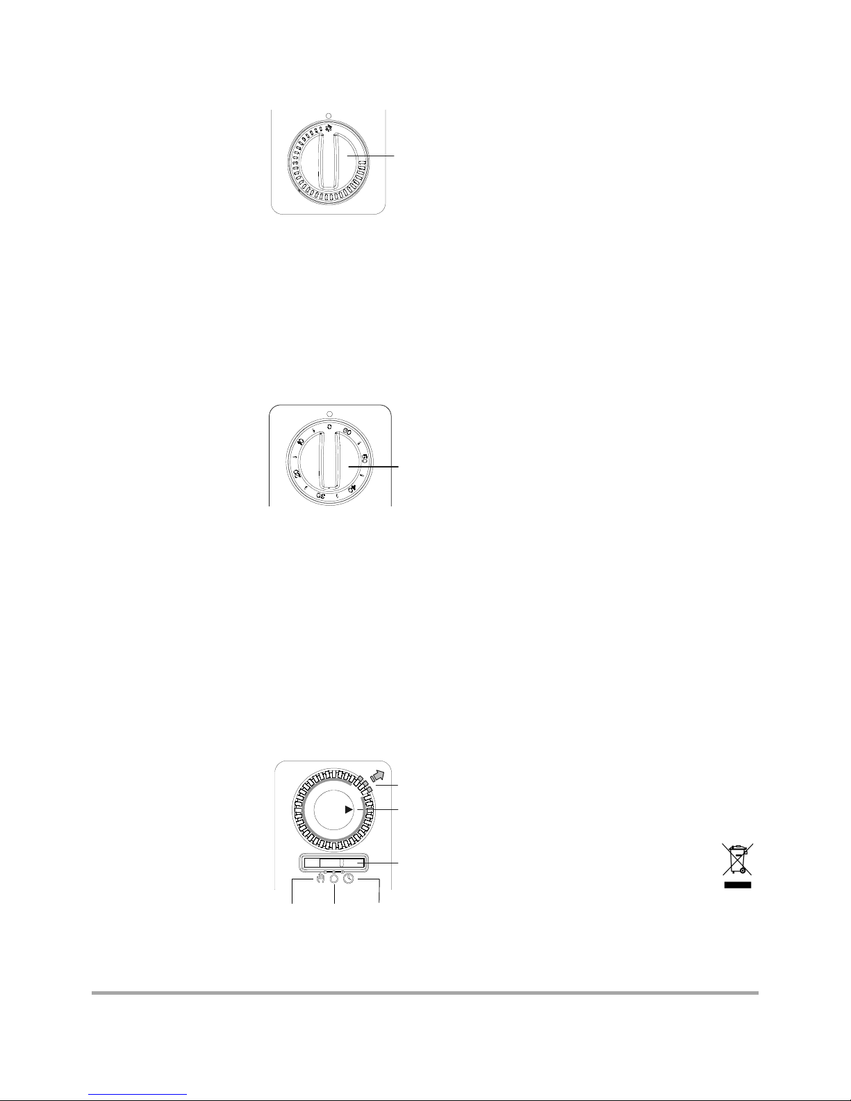
Die Raumtemperatur wird über
den stufenlos einstellbaren
Thermostaten (A) geregelt.
Wird der Drehknopf auf die
kleinste Einstellung ganz nach
links gestellt (siehe Bild) schaltet der Thermostat bei etwa 5
°C Umgebungstemperatur das
Heizgerät ein.
Achtung!
Je nach Raumgröße, Wärmebedarf und Thermostateinstellung
können Räume bei unbeaufsichtigter Beheizung überheizt
werden. Dies kann zu Gefahren für Personen führen, die nicht
in der Lage sind, den Raum bei überhöhter Temperatur zu verlassen.
EF 12/20 TI - Modelle mit 60 Minuten Zeitschaltuhr
Drehknopf (B) der Zeitschaltuhr im Uhrzeigersinn drehen. Gewünschte Zeitdauer einstellen (maximal 60 Minuten möglich).
Während des Ablaufes der eingestellten Zeit, arbeitet das Gerät mit der vollen Leistung von
2000 W. Nach Ablauf der eingestellten Zeit schaltet das Gerät
auf eine geringere Heizstufe von
1000 W. Beide Stufen werden
über den Thermostat geregelt.
Die eingestellte Zeit kann jederzeit am Drehknopf (B) verändert oder rückgängig gemacht
werden.
EF 12/20 TID - Modelle mit 24 Stunden Zeitschaltuhr
Mit der Schaltuhr können die Betriebszeiten des Heizgerätes
in einem Tagesprogramm (24 Stunden) eingestellt werden.
Für Automatikbetrieb Schiebeschalter (C) nach rechts auf Position „Uhr“ stellen.
Uhrzeit einstellen: Schaltuhr (D) im Uhrzeigersinn drehen, bis
die aktuelle Uhrzeit an der Markierung steht.
Heizgerät Ein: Segmente (E) nach außen schieben.
Heizgerät Aus: Segmente (E) nach innen schieben.
Jedes Segment entspricht einer Ein- oder Ausschaltdauer von
20 Minuten. Um z.B. eine Einschaltdauer von einer Stunde einzustellen, werden 3 Segmente nach außen geschoben.
Die Schaltuhr kann für mehrere
"Ein/Aus- Phasen unterschiedlicher Länge programmiert werden. Der Thermostat sorgt für
eine gleichmäßige Raumtemperatur während der Einschaltzeit.
Außerhalb der Einschaltzeit erfolgt kein Heizbetrieb und somit
auch kein Frostschutz.
Manuell Aus Uhr
Der Betrieb über die Schaltuhr kann jederzeit durch Umstellen
auf „Manuell“ oder "0" (Aus) außer Kraft gesetzt werden.
Die Schaltuhr läuft nur, wenn das Gerät an die Stromversorgung angeschlossen ist.
6. Überhitzungsschutz
Bei unzulässiger Erwärmung wird das Heizgerät automatisch
abgeschaltet. In diesem Fall Netzstecker ziehen und Gerät für
einige Minuten ausgesteckt lassen, damit der Temperaturbegrenzer wieder zurückschalten kann.
Anschließend mögliche Ursache beseitigen, z.B. Luftgitter verstellt oder abgedeckt. Wenn das Gerät ausreichend abgekühlt
ist, kann es wieder in Betrieb genommen werden.
7. Störungen
Wenn das Heizgerät keine Wärme abgibt, überprüfen Sie bitte
die folgenden Punkte:
• Thermostat auf gewünschte Temperatur gestellt?.
• Überhitzungsschutz ausgelöst? Siehe Kapitel 6!
• Sicherung im Sicherungskasten eingeschaltet?
• EF 12/20 TID: Schiebeschalter und Segmente korrekt eingestellt - siehe Kapitel 5 „Heizbetrieb EF 12/20 TID“.
Kann die Störung nicht behoben werden, wenden Sie sich bitte
an Ihre Elektrofachwerkstatt oder an die nächstgelegene Kundendienststelle.
Für die Auftragsbearbeitung werden die E-Nummer und FDZahl des Gerätes benötigt. Diese Angaben finden Sie auf dem
Typschild.
Reparaturen und Eingriffe in das Gerät dürfen nur von einem
Elektrofachmann oder dem Kundendienst ausgeführt werden.
8. Kundendienst
Robert Bosch Hausgeräte GmbH
Auftragsannahme
Telefon +49 (0) 1801 22 33 55
Telefax +49 (0) 1801 33 53 07
Ersatzteilbestellungen
Telefon +49 (0) 1801 33 53 04
Telefax +49 (0) 1801 33 53 08
E-Mail spareparts@bshg.com
Ersatzteilbestellungen im Internet unter:
http://www.dimplex.de
9. Reinigung
Zur Reinigung muss das Gerät vom Netz getrennt und abgekühlt sein. Die Außenseite kann durch Abwischen mit einem
weichen, feuchten Lappen gereinigt werden. Zur Reinigung
keine Scheuerpulver oder Möbelpolituren verwenden, da diese
die Oberfläche beschädigen können. Staubansammlungen im
Gerät können von außen mit einem Staubsauger abgesaugt
werden.
10. Garantie
Für dieses Produkt übernehmen wir 2 Jahre Garantie gemäß
unseren Garantiebedingungen.
11. Entsorgungshinweis
Das Gerät nicht im allgemeinen Hausmüll entsorgen
sondern einer örtlichen Entsorgungsstelle zuführen.
A
B
D
E
C
ef12-d_ba 03/09/A
Page 4
4
Installation and Operating Instructions
EF12/20, EF 12/20 TI, EF 12/20 TID, EF 12/10
1. Important Information
Keep these instructions in a safe place and pass them on to
possible future owners.
• The device is only suitable for room heating within enclosed
rooms.
• Repairs and corrective measures may only be carried out by
a qualified technician.
• Disconnect the power supply in the event of a fault (pull out
the device plug or switch off the fuse).
• Do not cover the heater with any objects; fire
hazard!
The device carries the symbol shown on the right,
which indicates that the heater must under no
circumstances be covered with any objects.
• Observe the minimum clearances.
• Caution! The outer surfaces of the device, and in particular
the air outlet grid, become hot during operation.
• Children or persons who are not capable of operating the
device safely must not operate the heater. Ensure that
children do not play with the device.
• Caution! Potential dangers can arise when the device
switches on automatically, e.g. devices which have been
covered or blocked by objects since they were last used can
cause fire.
• Do not operate the heater in rooms where highly
inflammable substances are used (e.g. solvents, etc.).
• Connecting lead must not be laid over the device.
2. Technical data
Heat output: EF 12/20, TI, TID: 2000 W
EF 12/10: 1000 W
Supply voltage: 1/N/PE~, 230 V, 50 Hz
Degree of protection: IP24, IP20 (EF 12/20 TID)
Safety class: I (with protective conductor)
Dimensions: (W x H x D) 300 x 405 x 120 mm
Weight: 3,25 kg
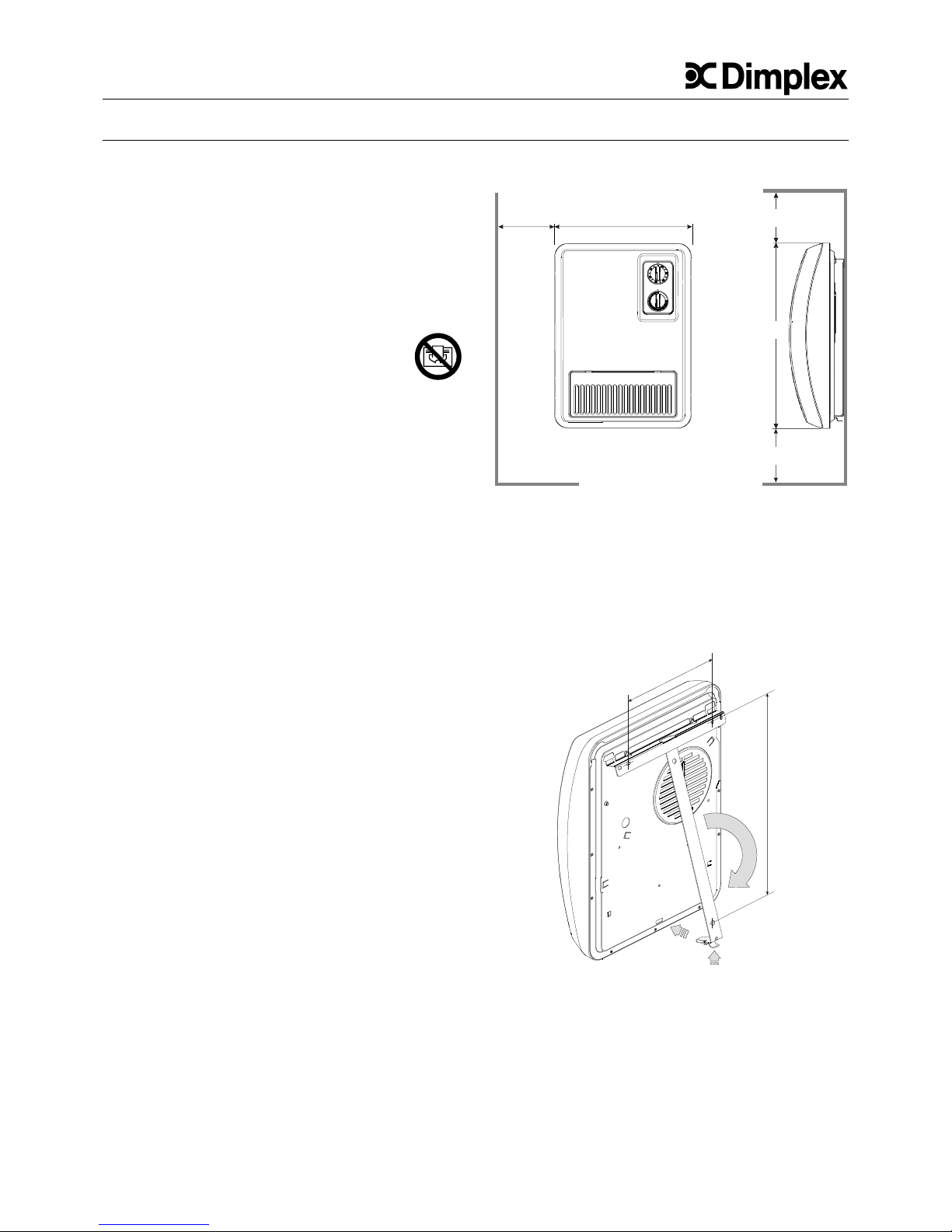
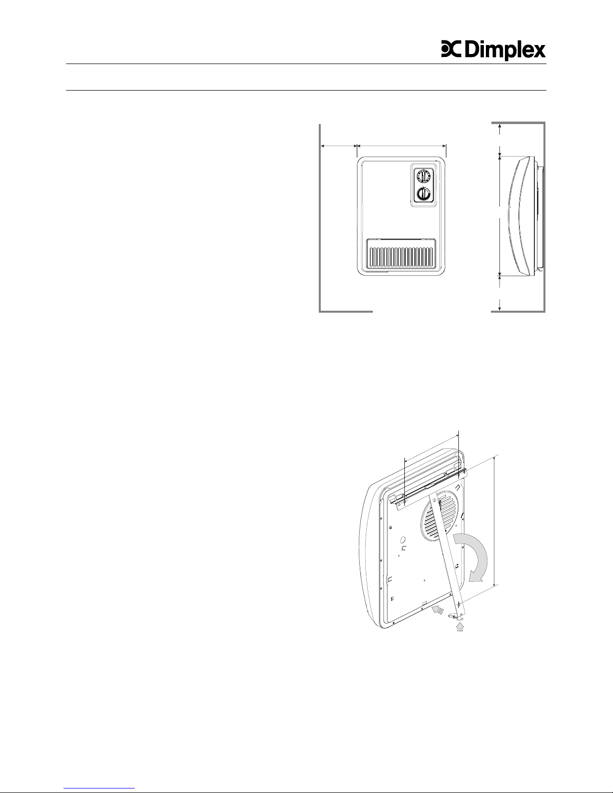
3. Installation
The heater must only be installed and operated on a vertical
wall as shown.
Installation below a wall socket is not permissible.
The device plug must be accessible after installation.
Install the device in such a manner that the controls cannot be
touched by a person in the bathtub or under the shower.
In addition, a minimum clearance of 750 mm between
inflammable objects e.g. curtains, towels or heat-sensitive
plastics, and the front of the unit must be maintained.
The device is mounted to the wall with 3 screws. The enclosed
plastic bag contains screws and dowels.
Observe the minimum clearances! Dimensions in mm.
Mounting Instruction
- Unlock the wall bracket (A) and remove from the device.
- Drill mounting holes for the wall bracket and insert the
dowels.
- Align the wall bracket and firmly screw it onto the wall.
- Hang the device on the wall mount.
- Pivot down the heater and push into place (B).
4. Electrical Connection
The voltage marked on the type plate must correspond to the
supply voltage (A.C supply only).
When the power line of this device is damaged, it must be
replaced by the manufacturer or after-sales service, or by a
similarly qualified person, in order to avoid risks.
Due to inadvertant resetting of the thermal cut-out, this
appliance must not be supplied through an external switching
device.
250 300
250
405
280
1
9
0
308
B
A
EN
Page 5
5
Glen Dimplex Deutschland GmbH Tel. +49 (0) 9221 709 564 Subject to technical changes
Am Goldenen Feld 18 Fax +49 (0) 9221 709 589 Internet: www.dimplex.de
D-95326 Kulmbach E-mail: kundendienst.hauswaerme@glendimplex.de
5. Heating operation
All Models
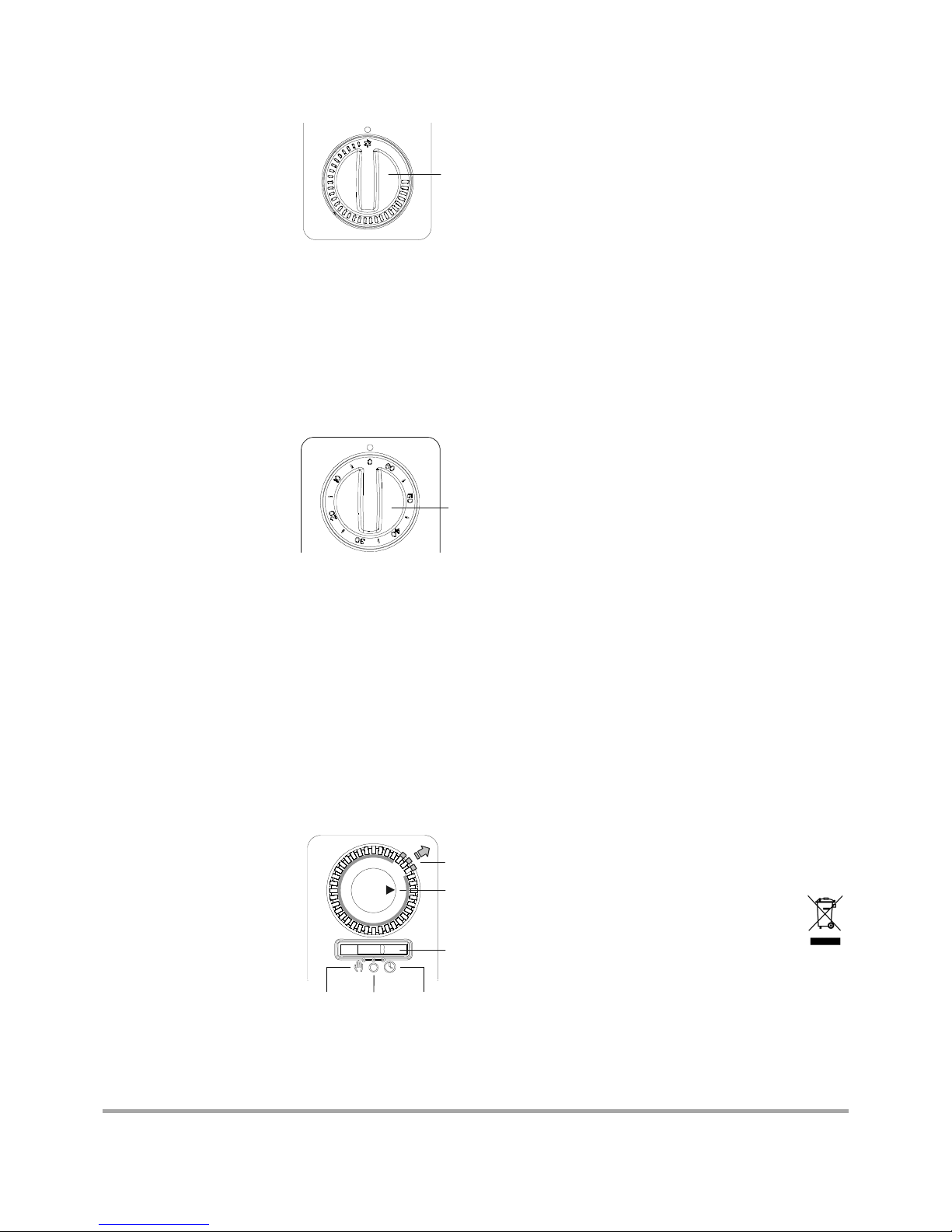
The room temperature is
regulated using the adjustable
thermostat (A). If the rotary
knob is set to the lowest setting
i.e. to the extreme left (see
figure), the thermostat switches
the heater on at an ambient
temperature of approx. 5°C.
Note!
Rooms can become overheated if left unattended whilst being
heated; this depends on the size of the room, its heating
requirements and the setting of the thermostat. Persons who
are not able to vacate the room if the temperature becomes too
high can thus be placed in danger.
EF 12/20 TI - Models with 60-minute timer
Turn the timer knob (B) in a clockwise direction. Set the desired
time period (up to 60 minutes).
During the time set, the device
runs at its full output of 2000 W.
When the set time has expired,
the device switches to a lower
(1000 W) heating level. Both
levels are controlled by the
thermostat.
The set time can be changed or
reversed at any time using the
timer knob (B).
EF 12/20 TID - Models with 24-hour timer
The operating hours of the heater can be set in a day program
(24 hours) using the timer.
For automatic operation, slide the switch (C) to the right into
"clock" position.
Setting the time:
Turn timer (D) clockwise until the marking matches up to the
current time.
Heater ON Slide segments outwards.
Heater OFF: Slide segments inwards.
Each segment represenets a switch-on or switch-off time of 20
minutes. In order, for example, to set a switch-on time of one
hour, 3 segments are slid outwards.
The timer can be programmed
for several ON/OFF phases of
different lengths. The
thermostat provides a uniform
room temperature during the
switch-on time.
Outside of the switching time, no
heating operation - and thus no
frost protection - takes place.
Manual OFF Timer
Operation via the timer can be deactivated at any time by
switching to "Manual" or "0" (OFF).
The timer only runs when the device is connected to the power
supply.
6. Protection Against Overheating
If the permissible temperature is exceeded, the heater
switches off automatically. If this occurs, pull the mains plug out
and leave the device unplugged for a few minutes, so that the
temperature limiter can switch back again.
Then remove the cause, e.g. when the air grid is blocked or
covered. When the device has cooled sufficiently, it can be
started up again.
7. Faults
If the heater does not give off heat, check the following points:
• Has the thermostat been set to the desired temperature?
• Has the overheat protection been triggered? See chapter 6!
• Is the fuse in the fuse box switched on?
• EF 12/20 TID: Set the slide switch and segments correctly see Chapter 5 "Heating Operation EF 12/20 TID".
If the fault cannot be corrected, please contact a specialist
electrical service center or else your nearest after-sales
service.
To process your order, please state the production number (E
No.) and manufacturing date (FD) of the device. This
information is listed on the type plate.
The device must only be repaired or manipulated by a skilled
electrician or the after-sales service.
8. After-sales service
Robert Bosch Hausgeräte GmbH
Order service
Tel. +49 (0) 1801 22 33 55
Fax +49 (0) 1801 33 53 07
Spare parts ordering
Tel. +49 (0) 1801 33 53 04
Fax +49 (0) 1801 33 53 08
E-mail spareparts@bshg.com
Spare parts can be ordered online at:
http://www.dimplex.de
9. Cleaning
To clean the device, first disconnect it from the mains and allow
it to cool down. Clean the outside of the unit using a soft, damp
cloth. Do not use scouring powder or furniture polish as this
may damage the surface. Dust which gathers inside the device
can be removed from the outside using a vacuum cleaner.
10. Warranty
This product is supplied with a two-year warranty according to
our terms of guarantee.
11. Note on Disposal
Do not dispose of the unit with general household
waste. The device must be taken to a local waste
disposal plant.
A
B
D
E
C
ef12-en_ba 03/09/A
Page 6
6
Instructions de montage et d’utilisation
EF 12/20, EF 12/20 TI, EF 12/20 TID, EF 12/10
1. Remarques importantes
Conservez précieusement ces instructions et remettez-les le
cas échéant au prochain propriétaire de l'appareil.
• L'appareil est destiné uniquement au réchauffement de l'air
ambiant de pièces fermées.
• Les réparations et interventions sur l'appareil ne doivent
être effectuées que par un technicien.
• En cas de dysfonctionnement, débrancher l'appareil (retirer
la fiche ou enlever le fusible).
• Ne pas couvrir l'appareil de chauffage, risque d'incendie !
Le symbole ci-contre est apposé sur l'appareil ; il signifie
que l'appareil de chauffage ne doit pas être couvert.
• Respecter les écartements minimaux.
• Prudence ! Lors du fonctionnement de l'appareil, les
surfaces extérieures et plus particulièrement la grille
d'échappement d'air deviennent très chaudes.
• L'appareil de chauffage ne doit pas être mis en service par
des enfants ou par des personnes qui ne sont pas en
mesure de l'utiliser en toute sécurité. S'assurer que les
enfants ne jouent pas avec l'appareil.
• Prudence ! Lorsque l'appareil se met automatiquement en
marche, des dangers peuvent survenir ; ainsi, des appareils
qui auraient été recouverts ou déplacés depuis la dernière
utilisation pourraient provoquer un incendie.
• Ne pas exploiter l'appareil dans des pièces où sont utilisées
des matières inflammables (telles que solvants, etc.).
• Ne pas poser le câble de raccordement sur l'appareil.
2. Caractéristiques techniques
Puissance calorifique : EF 12/20, TI, TID : 2 000 W
EF 12/10 : 1 000 W
Tension de raccordement : 1/N/PE~, 230 V, 50 Hz
Degré de protection : IP24, IP20 (EF 12/20 TID)
Classe de protection : I (avec conducteur de protection)
Dimensions : (L x H x P) 300 x 405 x 120 mm
Poids : 3,25 kg
3. Installation, montage
Monter et faire fonctionner l'appareil uniquement le long d'un
mur vertical comme illustré.
Il est interdit de monter l'appareil en dessous d'une prise de
courant murale.
La fiche de l'appareil doit être accessible une fois l’appareil
monté.
Installer l’appareil de sorte qu’une personne prenant un bain ou
une douche ne puisse entrer en contact avec les organes de
commande.
Respecter en outre un écartement minimal de 750 mm entre la
face frontale de l'appareil et des objets inflammables, tels que
rideaux, serviettes ou plastiques sensibles à la chaleur.
L'appareil doit être fixé au mur par trois vis. La poche en
plastique contient des vis et des chevilles.
Respecter les écartements min. ! Les dimensions sont en mm.
Opérations de montage
- Appuyez sur la languette de la partie inférieure du support
mural (A) pour dégager ce dernier de l'appareil.
- Dans le mur, percez des trous pour fixer le support et
insérez les chevilles.
- Positionnez le support mural et vissez-le fermement au mur
- Accrochez l'appareil au support mural.
- Faites pivoter l'appareil vers le bas et enclenchez-le (B).
4. Raccordement électrique
La tension et la fréquence indiquées sur la plaque signalétique
de l'appareil doivent être conformes à celles du circuit
d'alimentation. Si le câble d'alimentation secteur de l'appareil
est endommagé, il doit être remplacé par le fabricant, le SAV
ou par une personne de mêmes qualifications, afin d'éviter tout
risque. Ne commandez pas l'appareil au moyen d'un dispositif
de commutation externe, cela pourrait entraîner une
réinitialisation involontaire du limiteur de température.
250 300
250
405
280
1
9
0
308
B
A
F
Page 7

7
Glen Dimplex Deutschland GmbH Tél. +49 (0) 9221 709 564 Sous réserve de modifications techniques
Am Goldenen Feld 18 Fax +49 (0) 9221 709 589 Internet : www.dimplex.de
D-95326 Kulmbach (Allemagne) Courriel : kundendienst.hauswaerme@glendimplex.de
5. Mode chauffage
Sur tous les modèles
La température ambiante est
réglée via un thermostat à
réglage graduel (A). Lorsque le
sélecteur rotatif est placé tout à
gauche, sur la plus petite valeur
(voir figure ci-dessous), le
thermostat met en service
l'appareil de chauffage à une
température ambiante de 5 °C env.
Attention !
Selon la taille de la pièce, le besoin en chaleur et le réglage du
thermostat, il y a risque de surchauffe dans les pièces laissées
sans surveillance durant le chauffage. Cela peut entraîner des
risques pour les personnes n’étant pas en mesure de quitter la
pièce en cas de température excessive.
EF 12/20 TI - Modèles dotés d'une minuterie de 60 minutes
Tournez le sélecteur rotatif de la minuterie (B) dans le sens des
aiguilles d'une montre. Réglez la durée de fonctionnement
souhaitée (60 minutes maximum).
Pendant l'écoulement de la
durée sélectionnée, l'appareil
fonctionne à la puissance
maximale de 2 000 W. Une fois
la durée réglée écoulée,
l'appareil commute sur le niveau
de puissance de chauffage
moindre de 1 000 W. Les deux
niveaux sont régulés par
l'intermédiaire du thermostat.
L'activation du sélecteur rotatif (B) permet à tout moment de
modifier ou d'annuler la durée réglée.
EF 12/20 TID - Modèles dotés d'une minuterie de 24 heures
Cette minuterie permet de régler les durées de fonctionnement
de l'appareil de chauffage sur 24 heures (programme
journalier). Pour régler l'appareil en automatique, poussez le
commutateur à coulisse (C) vers la droite sur « minuterie ».
Réglage de l'horaire: Tournez le sélecteur rotatif de la
minuterie (D) dans le sens des aiguilles d'une montre jusqu'à
ce que l'heure actuelle coïncide avec la marque.
Appareil en marche : poussez les segments (E) vers l'extérieur.
Appareil à l'arrêt : poussez les segments (E) vers l'intérieur.
Chaque segment correspond à une durée de fonctionnement/
d'arrêt de 20 minutes. Ainsi, pour régler une durée de
fonctionnement d'une heure, vous devez poussez trois
segments vers l'extérieur.
La minuterie peut être programmée sur plusieurs phases de
marche/d'arrêt de longueur
différente. Le thermostat
garantit une température
ambiante homogène pendant
toute la durée de fonctionnement. En dehors de celle-ci,
l'appareil est hors service, et par
conséquent aucune protection
antigel n'est assurée. manuel arrêt minuterie
En commutant sur « manuel » ou « 0 » (arrêt), vous pouvez à
tout moment interrompre le fonctionnement de la minuterie.
Celle-ci fonctionne uniquement lorsque l'appareil est raccordé
au circuit.
6. Protection contre la surchauffe
En cas de surchauffe inadmissible, l'appareil de chauffage se
met automatiquement hors service. Dans ce cas, retirez la
prise secteur et laissez l'appareil débranché durant quelques
minutes, jusqu'à ce que le limiteur de température puisse
rétrograder. Puis éliminez les causes possibles (grille d'air
recouverte ou obturée par ex.). Lorsque l'appareil a
suffisamment refroidi, il peut être remis en service.
7. Dysfonctionnements
Si l'appareil de chauffage ne chauffe pas, veuillez vérifier les
points suivants :
• Le thermostat est-il positionné sur la température souhaitée ?
• La protection contre la surchauffe est-elle déclenchée ?
• Le fusible (situé dans la boîte de fusibles) est-il actif ?
• EF 12/20 TID : Le commutateur à coulisse et les segments
sont-ils réglés correctement ?
Si vous n'êtes pas en mesure de remédier au dysfonctionnement, veuillez vous adresser à votre électricien ou au service
après-vente le plus proche.
Pour traiter votre commande, veuillez nous communiquer le
numéro E et la date de fabrication FD de l'appareil.
Ces indications figurent sur la plaque signalétique de l’appareil.
Les réparations et interventions sur l’appareil ne doivent être
réalisées que par un électricien qualifié ou le service aprèsvente.
8. Service après-vente
Robert Bosch Hausgeräte GmbH
Réception des commandes
Téléphone +49 (0) 1801 22 33 55, Téléfax 33 53 07
Commande de pièces de rechange
Téléphone +49 (0) 1801 33 53 04, Téléfax 33 53 08
Courriel : spareparts@bshg.com
Vous pouvez commander vos pièces de rechange
par Internet : http://www.dimplex.de
9. Nettoyage
Avant de procéder au nettoyage, mettre l'appareil hors tension
et le laisser refroidir. La surface extérieure de l'appareil peut
être nettoyée avec un linge doux et humide. Pour le nettoyage,
ne pas utiliser de poudre à récurer ou d'encaustique qui
pourraient endommager les surfaces. Les dépôts de poussière
dans l'appareil peuvent être aspirés depuis l'extérieur de
l'appareil.
10. Garantie
Conformément aux conditions de garantie, nous accordons 2
ans de garantie sur ce produit.
11. Remarque sur la mise au rebut de l’appareil
L’appareil ne doit pas être éliminé avec les ordures
ménagères mais via un poste local d’élimination.
A
B
D
E
C
ef12-f_ba 03/09/A
Page 8

8
Istruzioni d'uso e di montaggio
EF 12/20, EF 12/20 TI, EF 12/20 TID, EF 12/10
1. Informazioni importanti
Conservare con cura queste istruzioni e consegnarle
eventualmente al successivo proprietario.
• L'apparecchio può essere utilizzato solo per il riscaldamento
dell'aria ambiente all'interno di ambienti chiusi.
• Riparazioni e interventi all'interno dell'apparecchio possono
essere svolti solo da un esperto.
• In caso di guasto, scollegare l'apparecchio dalla rete elettrica
(staccare la spina dell'apparecchio o disinserire il fusibile).
• Non coprire l'apparecchio - pericolo di incendio.
Il simbolo a fianco è applicato all'apparecchio di
riscaldamento e indica che l'apparecchio di riscaldamento
non deve essere coperto.
• Mantenere le distanze minime.
• Attenzione! Le superfici esterne e in particolare la griglia di
fuoriuscita aria si scaldano durante l'utilizzo.
• Non permettere l'utilizzo dell'apparecchio a bambini o altre
persone non in grado di utilizzare l'apparecchio in sicurezza.
Assicurarsi che i bambini non giochino con l'apparecchio.
• Attenzione! Dopo l'accensione automatica dell'apparecchio
possono insorgere dei pericoli: ad esempio gli apparecchi
coperti o spostati nel frattempo potrebbero provocare degli
incendi.
• Non è consentito l'utilizzo dell'apparecchio di riscaldamento
in ambienti in cui si impieghino prodotti infiammabili (p.es.
solventi, ecc.).
• Non far passare la linea di allacciamento sopra l'apparecchio.
2. Dati tecnici
Potenza calorifica: EF 12/20, TI, TID: 2000 W
EF 12/10: 1000 W
Tensione di collegamento: 1/N/PE~, 230 V, 50 Hz
Grado di protezione:
IP24, IP20 (EF 12/20 TID)
Classe di protezione I (con conduttore di protezione)
Dimensioni: (L x A x P) 300 x 405 x 120 mm
Peso:
3,25
kg
3. Installazione, montaggio
L'apparecchio di riscaldamento può essere montato e utilizzato
solo su una parete verticale, come mostrato in figura.
Il montaggio sotto una presa elettrica a muro non è consentito.
La spina dell'apparecchio deve essere accessibile dopo il
montaggio.
L'apparecchio deve essere installato in modo tale che gli
elementi di comando non possano essere toccati da una
persona che si trovi nella vasca da bagno o sotto la doccia.
Inoltre è necessario rispettare anche una distanza di almeno
750 mm fra il lato anteriore dell'apparecchio e oggetti facilmente
infiammabili, ad esempio tende, asciugamani o materie
plastiche sensibili al calore.
L'apparecchio deve essere fissato alla parete con 3 viti. Le viti e
i tasselli sono contenuti nel sacchetto di plastica.
Mantenere le distanze minime! Misure in mm.
Procedura di montaggio
- Sbloccare il supporto a parete in basso (A) e staccarlo
dall'apparecchio.
- Praticare dei fori di fissaggio per il supporto a parete e
inserire i tasselli.
- Allineare il supporto a parete e avvitarlo saldamente alla
parete.
- Appendere l'apparecchio al supporto a parete.
- Girare l'apparecchio di riscaldamento verso il basso e farlo
scattare in sede (B).
4. Allacciamento elettrico
L'indicazione della tensione e della frequenza sulla targhetta
deve coincidere con i valori della corrente elettrica di rete
disponibile. In caso di danni al cavo di allacciamento alla rete di
questo apparecchio, la sostituzione deve essere eseguita dal
produttore o dal relativo servizio clienti oppure da personale
analogamente qualificato per evitare rischi.
Non azionare l'apparecchio di riscaldamento tramite un
apparecchio esterno di commutazione. In tal caso si potrebbe
causare un reset accidentale del limitatore di temperatura.
250 300
250
405
280
1
9
0
308
B
A
I
Page 9

9
Glen Dimplex Deutschland GmbH Telefono +49 (0) 9221 709 564 Con riserva di modifiche tecniche
Am Goldenen Feld 18 Telefax +49 (0) 9221 709 589 Internet: www.dimplex.de
D-95326 Kulmbach E-mail: kundendienst.hauswaerme@glendimplex.de
5. Esercizio di riscaldamento
Tutti i modelli
La temperatura ambiente viene
regolata tramite il termostato a
regolazione continua (A).
Ruotando completamente la
manopola a sinistra in
corrispondenza
dell'impostazione più bassa
(vedere figura), il termostato
accende l'apparecchio di
riscaldamento a una temperatura ambiente di 5 °C circa.
Attenzione!
A seconda della dimensione della stanza, del fabbisogno di
calore e dell’impostazione del termostato, si corre il rischio di
surriscaldamento in ambienti non sottoposti a controllo del
riscaldamento
.
Ciò può comportare pericoli per le persone che
non sono in grado di abbandonare la stanza in caso di
temperature elevate.
EF 12/20 TI - Modelli con timer da 60 minuti
Ruotare la manopola (B) del timer in senso orario. Impostare la
durata desiderata (massimo 60 minuti).
Nel corso della durata impostata,
l'apparecchio lavora alla massima
potenza di 2000 W. Al termine
della durata impostata,
l'apparecchio passa a un livello di
riscaldamento inferiore di 1000
W. Entrambi i livelli sono regolati
dal termostato. La durata
impostata può essere modificata
o annullata in qualsiasi momento con la manopola (B).
EF 12/20 TID - Modelli con timer da 24 ore
Il timer permette di impostare i periodi di esercizio
dell'apparecchio di riscaldamento in un programma giornaliero
(24 ore). Per il funzionamento in automatico, portare
l'interruttore scorrevole (C) a destra in posizione "Orologio".
Impostazione dell'ora:
Ruotare il timer (I) in senso orario fino a portare l'ora corrente in
corrispondenza della marcatura.
Accensione dell'apparecchio di riscaldamento: spingere i
cavalieri (E) verso l'esterno.
Spegnimento dell'apparecchio di riscaldamento: spingere i
cavalieri (E) verso l'interno.
Ogni segmento corrisponde a un
periodo di accensione o
spegnimento di 20 minuti. Ad
esempio, per impostare un
periodo di accensione di un'ora
occorre spingere 3 cavalieri
verso l'esterno. Il timer può
essere programmato per più fasi
di accensione/spegnimento di
lunghezza diversa.
Manuale Spento Orologio
Il termostato assicura una temperatura ambiente omogenea
durante il periodo di accensione. Al di fuori dei periodi di
accensione, l'esercizio di riscaldamento è escluso e non è quindi
disponibile la protezione antigelo (fonte di calore).
L'utilizzo tramite timer può essere disattivato in qualunque
momento portando l'interruttore su "Manuale" o "0" (spento).
Il timer funziona solo se l'apparecchio è collegato alla rete
elettrica.
6. Protezione antisurriscaldamento
In caso di riscaldamento oltre i limiti consentiti, l'apparecchio di
riscaldamento si spegne automaticamente. In questo caso,
staccare la spina di rete e lasciare scollegato l'apparecchio per
alcuni minuti per far nuovamente scattare il limitatore di
temperatura.
Eliminare quindi la possibile causa di riscaldamento, ad esempio
lo spostamento o la copertura della griglia di ventilazione.
Quando l'apparecchio si è raffreddato a sufficienza, è possibile
rimetterlo in funzione.
7. Guasti
Se l'apparecchio di riscaldamento non emette calore, controllare
i seguenti punti:
• Il termostato è regolato alla temperatura desiderata?
• La protezione antisurriscaldamento è scattata?
• Il fusibile nell'apposita cassetta è scattato?
• EF 12/20 TID: L'interruttore scorrevole e i cavalieri sono
impostati correttamente?
Se non è possibile risolvere il guasto, si prega di contattare il
proprio elettricista specializzato o il centro di Servizio clienti più
vicino. Per la lavorazione della pratica è necessario indicare il
numero di serie e il codice FD dell'apparecchio. Queste
informazioni sono riportate sulla targhetta.
Riparazioni e interventi all'interno dell'apparecchio possono
essere svolti solo da un elettricista esperto o dal Servizio clienti.
8. Servizio clienti
Robert Bosch Hausgeräte GmbH
Accettazione dell'ordine
Telefono +49 (0) 1801 22 33 55, Telefax 33 53 07
Ordini per pezzi di ricambio
Telefono +49 (0) 1801 33 53 04, Telefax 33 53 08
E-mail spareparts@bshg.com
Ordini per pezzi di ricambio tramite Internet:
http://www.dimplex.de
9. Pulizia
Per la pulizia occorre scollegare l'apparecchio dalla rete elettrica
e lasciarlo raffreddare. L'esterno può essere pulito strofinando
con un panno morbido e inumidito. Non utilizzare polveri
abrasive o lucidi per mobili per evitare di danneggiare la
superficie. I depositi di polvere nell'apparecchio possono essere
aspirati dall'esterno con un aspirapolvere.
10. Garanzia
Questo prodotto è garantito 2 anni secondo le condizioni di
garanzia.
11. Nota per lo smaltimento
L'apparecchio non deve essere smaltito nei rifiuti
domestici generici, ma deve essere conferito a un
centro di smaltimento locale.
A
B
D
E
C
ef12-i_ba 03/09/A
Page 10

10
Οδηγίες τοποθέτησης και χρήσης
EF12/20, EF 12/20 TI, EF 12/20 TID, EF 12/10
1. Σημαντικές υποδείξεις
Φυλάξτε προσεκτικά αυτές τις οδηγίες και παραδώστε τις στον
επόμενο κάτοχο.
• Η συσκευή είναι κατάλληλη μόνο για θέρμανση αέρα κλειστών
χώρων.
• Η διενέργεια επισκευών και επεμβάσεων στη συσκευή
επιτρέπεται μόνο από ειδικό.
• Σε περίπτωση βλάβης, αποσυνδέστε τη συσκευή από το
ηλεκτρικό δίκτυο (αποσυνδέστε το φις ή κλείστε την ασφάλεια).
• Μην καλύπτετε τη συσκευή θέρμανσης, κίνδυνος πυρκαγιάς!
Το διπλανό σύμβολο υπάρχει στη συσκευή θέρμανσης και
σημαίνει ότι δεν επιτρέπεται να καλύπτετε τη συσκευή
θέρμανσης.
• Τηρείτε τις ελάχιστες αποστάσεις ασφαλείας.
• Προσοχή! Στις εξωτερικές επιφάνειες και ιδίως στο πλέγμα
εξόδου αέρα αναπτύσσονται κατά τη λειτουργία υψηλές
θερμοκρασίες.
• Μην αφήνετε παιδιά ή
άλλα άτομα να χειρίζονται τη συσκευή, τα
οποία δεν είναι σε θέση να χρησιμοποιούν με ασφάλεια τη
συσκευή. Βεβαιωθείτε ότι δεν παίζουν παιδιά με τη συσκευή.
• Προσοχή! Μετά την αυτόματη ενεργοποίηση της συσκευής
ενδέχεται να προκύψουν κίνδυνοι, π.χ. πυρκαγιά από
συσκευές που είναι καλυμμένες ή έχουν μετακινηθεί.
• Δεν
επιτρέπεται η λειτουργία της συσκευής σε χώρους όπου
χρησιμοποιούνται εύφλεκτα υλικά (π.χ. διαλυτικά κτλ.).
• Δεν επιτρέπεται η τοποθέτηση του καλωδίου σύνδεσης πάνω
από τη συσκευή.
2. Τεχνικά χαρακτηριστικά
Θερμαντική ισχύς: EF 12/20, TI, TID: 2000 W
EF 12/10: 1000 W
Τάση σύνδεσης: 1/N/PE~, 230 V, 50 Hz
Είδος προστασίας: IP24, IP20 (EF 12/20 TID)
Κατηγορία προστασίας:I (με αγωγό προστασίας)
Διαστάσεις: (Π x Υ x Β) 300 x 405 x 120 mm
Βάρος: 3,25 kg
3. Στήσιμο, τοποθέτηση
Η συσκευή θέρμανσης επιτρέπεται να τοποθετείται και να
λειτουργεί μόνο όπως απεικονίζεται σε κάθετο τοίχο.
Δεν επιτρέπεται η τοποθέτηση κάτω από μια πρίζα τοίχου.
Μετά την τοποθέτηση, πρέπει να έχετε πρόσβαση στο φις της
συσκευής.
Η συσκευή πρέπει να τοποθετείται έτσι ώστε να μην μπορεί
κάποιο άτομο που βρίσκεται στην μπανιέρα
ή στο ντους να έρθει
σε επαφή με τα χειριστήρια.
Εκτός αυτού, πρέπει να υπάρχει και από την μπροστινή πλευρά
απόσταση τουλάχιστον 750 mm από εύφλεκτα αντικείμενα, όπως
π.χ. κουρτίνες, πετσέτες ή ευαίσθητα στις υψηλές θερμοκρασίες
πλαστικά.
Η συσκευή πρέπει να στερεώνεται με 3 βίδες στον τοίχο. Στο
πλαστικό σακουλάκι υπάρχουν βίδες
και ούπατ.
Τηρείτε τις ελάχιστες αποστάσεις ασφαλείας! Διαστάσεις σε mm.
Διαδικασία τοποθέτησης
- Απασφαλίστε την επίτοιχη βάση κάτω (Α) και αφαιρέστε τη από
τη συσκευή.
- Ανοίξτε τρύπες στερέωσης για την επίτοιχη βάση και
τοποθετήστε τα ούπατ.
- Ευθυγραμμίστε την επίτοιχη βάση και βιδώστε την καλά στον
τοίχο.
- Αναρτήστε τη συσκευή στην επίτοιχη βάση.
- Μετακινήστε προς τα κάτω τη συσκευή θέρμανσης και
ασφαλίστε
τη (B).
4. Ηλεκτρική σύνδεση
Τα στοιχεία τάσης και συχνότητας που αναγράφονται στην
πινακίδα τύπου πρέπει να συμπίπτουν με τα στοιχεία
τροφοδοσίας του υπάρχοντος ηλεκτρικού δικτύου.
Σε περίπτωση που υποστεί ζημιά το καλώδιο τροφοδοσίας της
συσκευής πρέπει, για την αποφυγή κινδύνων, να αντικαθίσταται
από τον κατασκευαστή ή από το σέρβις του ή από έναν
εξειδικευμένο
τεχνικό.
Μη χειρίζεστε τη συσκευή θέρμανσης με εξωτερική διάταξη
διακοπτών. Το γεγονός αυτό θα μπορούσε να προκαλέσει ακούσια
απενεργοποίηση του θερμοστάτη.
250 300
250
405
280
1
9
0
308
B
A
GR
Page 11

11
Glen Dimplex Deutschland GmbH Τηλέφωνο +49 (0) 9221 709 564 Διατηρούμε το δικαίωμα τεχνικών τροποποιήσεων
Am Goldenen Feld 18 Φαξ +49 (0) 9221 709 589 Internet: www.dimplex.de
D-95326 Kulmbach Email: kundendienst.hauswaerme@glendimplex.de
5. Λειτουργία θέρμανσης
Όλα τα μοντέλα
Η θερμοκρασία του χώρου ρυθμίζεται
με έναν αδιαβάθμητα ρυθμιζόμενο
θερμοστάτη (A). Περιστρέφοντας τον
περιστροφικό διακόπτη στη θέση
ελάχιστης ρύθμισης τελείως αριστερά
(βλέπε εικόνα), ο θερμοστάτης
ενεργοποιεί τη συσκευή θέρμανσης
όταν η θερμοκρασία του
περιβάλλοντος είναι περίπου 5 °C.
Προσοχή!
Ανάλογα με το μέγεθος του δωματίου, τις ανάγκες θέρμανσης και
τη ρύθμιση του θερμοστάτη
ενδέχεται να υπερθερμανθούν
δωμάτια στα οποία δεν επιτηρείται η θέρμανση. Το γεγονός αυτό
μπορεί να προκαλέσει κινδύνους για άτομα, τα οποία δεν είναι σε
θέση να εγκαταλείψουν το χώρο σε περίπτωση υπερβολικής
θερμοκρασίας.
EF 12/20 TI - Μοντέλα με χρονοδιακόπτη 60 λεπτών
Περιστρέψτε δεξιόστροφα τον περιστροφικό διακόπτη (B) του
χρονοδιακόπτη. Ρυθμίστε την επιθυμητή χρονική διάρκεια
(μέγιστη διάρκεια 60 λεπτά).
Κατά τη διάρκεια του επιλεγμένου
χρόνου, η συσκευή λειτουργεί με την
πλήρη ισχύ των 2000 W. Ο
θερμοστάτης είναι εκτός λειτουργίας.
Μετά την παρέλευση του
επιλεγμένου χρόνου, η συσκευή
λειτουργεί με μειωμένη θερμαντική
ισχύ 1000 W, η οποία ρυθμίζεται
μέσω του θερμοστάτη.
Μπορείτε να τροποποιήσετε ή να ακυρώσετε ανά πάσα στιγμή με
τον περιστροφικό διακόπτη (Β) τον επιλεγμένο χρόνο.
EF 12/20 TD - Μοντέλα με χρονοδιακόπτη 24 ωρών
Με το χρονοδιακόπτη μπορείτε να ρυθμίσετε τις ώρες λειτουργίας
της συσκευής θέρμανσης σε ένα ημερήσιο πρόγραμμα (24 ώρες).
Για αυτόματη λειτουργία, μετακινήστε το συρόμενο διακόπτη (C)
προς τα δεξιά στη θέση „Ρολόι“.
Ρύθμιση ώρας:
Περιστρέψτε το χρονοδιακόπτη (D) δεξιόστροφα, μέχρι να
εμφανιστεί η τρέχουσα ώρα στο σημάδι.
Συσκευή θέρμανσης σε λειτουργία: Σπρώξτε τα επιμέρους
τμήματα (E) προς τα έξω.
Συσκευή θέρμανσης εκτός λειτουργίας: Σπρώξτε τα επιμέρους
τμήματα (E) προς τα μέσα.
Κάθε επιμέρους τμήμα αντιστοιχεί σε διάρκεια ενεργοποίησης ή
απενεργοποίησης 20 λεπτών. Για να ρυθμίσετε για παράδειγμα
διάρκεια ενεργοποίησης μίας ώρας, σπρώξτε 3 επιμέρους
τμήματα προς τα έξω.
Μπορείτε να προγραμματίσετε το
χρονοδιακόπτη για πολλές φάσεις
"εντός/εκτός
λειτουργίας"
διαφορετικής διάρκειας. Ο
θερμοστάτης φροντίζει για
ομοιόμορφη θερμοκρασία κατά τη
διάρκεια του χρόνου
ενεργοποίησης.
Εκτός του χρόνου ενεργοποίησης
δεν λειτουργεί η θέρμανση και
επομένως ούτε η προστασία από
παγετό.
Χειροκίνητα Εκτός Χρονοδ.
Μπορείτε να ακυρώσετε ανά πάσα στιγμή τη λειτουργία του
χρονοδιακόπτη επιλέγοντας „Χειροκίνητα“ ή "0" (εκτός
λειτουργίας).
Ο χρονοδιακόπτης λειτουργεί μόνο όταν η συσκευή είναι
συνδεδεμένη στο ηλεκτρικό δίκτυο.
6. Προστασία υπερθέρμανσης
Σε περίπτωση υπερθέρμανσης απενεργοποιείται αυτόματα η
συσκευή θέρμανσης. Σε αυτήν την περίπτωση, αποσυνδέστε το
φις από την πρίζα και αφήστε τη συσκευή μερικά λεπτά
αποσυνδεδεμένη για να μπορεί να επανέλθει ο θερμοστάτης.
Αποκαταστήστε στη συνέχεια τη βλάβη, π.χ. μετακίνηση ή κάλυψη
πλέγματος αέρα. Όταν κρυώσει επαρκώς η συσκευή, μπορείτε να
τη θέσετε ξανά σε λειτουργία.
7. Βλάβες
Εάν η συσκευή θέρμανσης δεν θερμαίνει, ελέγξτε τα παρακάτω
σημεία:
• Έχετε ρυθμίσει το θερμοστάτη στην επιθυμητή θερμοκρασία;
• Ενεργοποιήθηκε η προστασία υπερθέρμανσης; Βλέπε
κεφάλαιο 6!
• Είναι ενεργοποιημένη η ασφάλεια στην ασφαλειοθήκη;
• EF 12/20 TID: Συρόμενος διακόπτης και επιμέρους τμήματα
σωστά ρυθμισμένα - βλέπε κεφάλαιο 5 „Λειτουργία θέρμανσης
EF 12/20 TID“.
Εάν δεν μπορείτε να αποκαταστήσετε τη βλάβη, απευθυνθείτε
στον ηλεκτρολόγο σας ή στο πλησιέστερο σέρβις.
Για την επεξεργασία του αιτήματός σας απαιτείται ο αριθμός Ε και
ο αριθμός FD της συσκευής. Τα στοιχεία αυτά αναγράφονται στην
πινακίδα τύπου.
Η διενέργεια επισκευών και επεμβάσεων στη συσκευή επιτρέπεται
μόνο από ηλεκτρολόγο ή από το σέρβις.
8. Σέρβις
Robert Bosch Hausgerte GmbH
Επισκευές
Τηλέφωνο +49 (0) 1801 22 33 55
Φαξ +49 (0) 1801 33 53 07
Παραγγελίες ανταλλακτικών
Τηλέφωνο +49 (0) 1801 33 53 04
Φαξ +49 (0) 1801 33 53 08
Email spareparts@bshg.com
Παραγγελίες ανταλλακτικών στο internet στη διεύθυνση:
http://www.dimplex.de
9. Καθαρισμός
Για τον καθαρισμό, η συσκευή πρέπει να έχει αποσυνδεθεί από το
ηλεκτρικό δίκτυο και να έχει κρυώσει. Μπορείτε να καθαρίσετε τις
εξωτερικές επιφάνειες σκουπίζοντάς τις με μαλακό, υγρό πανί. Μη
χρησιμοποιείτε για καθαρισμό σκόνη ή στιλβωτικά επίπλων, διότι
ενδέχεται να προκληθούν ζημιές στην επιφάνεια. Μπορείτε να
καθαρίσετε τη σκόνη που έχει
συγκεντρωθεί μέσα στη συσκευή
εξωτερικά με ηλεκτρική σκούπα.
10. Εγγύηση
Για το προϊόν αυτό παρέχεται εγγύηση 2 ετών σύμφωνα με τους
όρους εγγύησης της εταιρείας μας.
11. Απόρριψη
Μη ρίπτετε τη συσκευή στα κοινά οικιακά απορρίμματα
αλλά παραδώστε τη στα τοπικά σημεία συλλογής ειδικών
απορριμμάτων.
A
B
D
E
C
ef12-gr_ba 03/09/A
Page 12

12
Instrukcja montażu i obsługi
EF12/20, EF 12/20 TI, EF 12/20 TID, EF 12/10
1. Ważne wskazówki
Niniejszą instrukcję należy starannie zachować i w razie
przekazania lub sprzedaży urządzenia przekazać ją nowemu
właścicielowi.
•Urządzenie jest przeznaczone do podgrzewania powietrza
w zamkniętych pomieszczeniach.
• Naprawy i konserwacje urządzenia może wykonywać
wyłącznie odpowiednio wykwalifikowany personel.
• W razie usterki odłączyć od sieci (wyjąć wtyk przewodu
zasilającego z gniazda lub wyłączyć bezpiecznik).
•Nie nakrywać grzejnika - niebezpieczeństwo
pożaru! Znajdujący się obok symbol jest
umieszczony na grzejniku i oznacza, że grzejnika
nie wolno przykrywać.
• Zachować minimalne odstępy.
• Uwaga! Powierzchnie zewnętrzne, a w szczególności
kratka wylotu powietrza, rozgrzewają się podczas pracy.
• Nie zezwalać na użytkowanie grzejnika dzieciom i innym
osobom, które nie są w stanie bezpiecznie się nim
posługiwać. Dopilnować, by dzieci nie bawiły się grzejnikiem.
• Uwaga! Po automatycznym włączeniu urządzenia mogą
powstać zagrożenia, np. na skutek przykrycia lub
przestawienia urządzenia.
•Urządzenia nie wolno używać w pomieszczeniach,
w których stosowane są substancje łatwopalne,
np. rozpuszczalniki.
•Nie wolno kłaść przewodu zasilającego na urządzeniu.
2. Dane techniczne
Moc grzewcza: EF 12/20, TI, TID: 2000 W
EF 12/10: 1000 W
Napięcie zasilania: 1/N/PE~, 230 V, 50 Hz
Typ ochrony:
IP24, IP20 (EF 12/20 TID)
Klasa ochrony: I (z przewodem ochronnym)
Wymiary: (szer. x głęb. x wys.) 300 x 405 x 120 mm
Masa: 3,25 kg
3. Ustawienie, montaż
Grzejnik może być zamontowany i eksploatowany tylko
w sposób przedstawiony na rysunku, na pionowej ścianie.
Montaż nad gniazdem zasilającym jest niedozwolony.
Wtyk przewodu zasilającego musi być dostępny po montażu.
Urządzenie należy tak zainstalować, by elementy obsługowe
były poza zasięgiem osoby znajdującej się w wannie lub pod
prysznicem.
Ponadto, należy zachować odstęp co najmniej 750 mm między
przednią stroną urządzenia a łatwopalnymi przedmiotami, jak
zasłony, ręczniki lub tworzywa sztuczne, wrażliwe na ciepło.
Urządzenie należy zamocować do ściany za pomocą trzech
śrub. W torebce z tworzywa znajdują się śruby i kołki.
Przestrzegać minimalnych odstępów! Wymiary w mm.
Przebieg montażu
-Odryglować (wyczepić) uchwyt ścienny (A) i zdjąć
zurządzenia.
-Wywiercić w ścianie otwory na kołki mocujące i wstawić
kołki.
-Wypoziomować uchwyt ścienny i mocno przykręcić do ściany.
-Zawiesić urządzenie na uchwycie ściennym.
-Pochylić urządzenie w dół i wcisnąć w zatrzaski (B).
4. Podłączenie elektryczne
Dane dotyczące napięcia i częstotliwości na tabliczce znamionowej
muszą być zgodne z danymi napięcia zasilania w sieci.
Jeżeli uszkodzeniu ulegnie przewód zasilający urządzenia,
w celu uniknięcia zagrożeń musi on zostać wymieniony przez
producenta, autoryzowany serwis producenta lub osobę
o podobnych kwalifikacjach.
Nie włączać i nie wyłączać urządzenia za pomocą
zewnętrznego włącznika/wyłącznika. Mogłoby to spowodować
niezamierzone zresetowanie ogranicznika temperatury.
250 300
250
405
280
1
9
0
308
B
A
PL
Page 13

13
Glen Dimplex Deutschland GmbH Telefon +49 (0) 9221 709 564 Zmiany techniczne zastrzeżone
Am Goldenen Feld 18 Telefaks +49 (0) 9221 709 589 Internet: www.dimplex.de
D-95326 Kulmbach E-mail: kundendienst.hauswaerme@glendimplex.de
5. Tryb grzania
Wszystkie modele
Temperaturę powietrza można
regulować za pomocą
termostatu (A) z bezstopniową
regulacją. W lewym skrajnym
położeniu pokrętła (patrz
ilustracja) termostat wyłącza
urządzenie przy temperaturze
otoczenia ok. 5 °C.
Uwaga!
W zalenoci od wielkoci pomieszczenia, zapotrzebowania na
ciepo i ustawienia termostatu moe przy braku kontroli
ogrzewania doj do przegrzania pomieszcze. Moe to
spowodowa zagroenie dla osób, które przy zbyt wysokiej
temperaturze nie s w stanie opuci pomieszczenie.
EF 12/20 TI - modele z zegarem załączającym na 60 minut
Pokrętło (B) zegara załączającego obrócić w prawo. Ustawić
żądany czas (maksymalnie 60 minut).
W ustawionym czasie urządzenie
pracuje z pełną mocą 2000 W. Po
upływie ustawionego czasu
urządzenie przełącza się na
mniejszą moc 1000 W. Pracą obu
stopni mocy steruje termostat.
Ustawiony czas można w każdej
chwili zmienić lub anulować za
pomocą pokrętła (B).
EF 12/20 TID - modele z zegarem załączającym na 24 godziny
Za pomocą zegara załączającego można ustawić czas pracy
urządzenia w cyklu dobowym (24 godziny).
W trybie pracy automatycznej suwak (C) przesunąć w prawo
do pozycji „Zegar”.
Ustawienie czasu zegara:
Pokrętło zegara (D) obrócić w prawo, aż strzałka znajdzie się
na bieżącej godzinie.
Włączenie grzejnika: wysunąć segmenty (E) na zewnątrz.
Wyłączenie grzejnika: wsunąć segmenty (E) do wewnątrz.
Każdy segment odpowiada cyklowi włączenia i wyłączenia
odługości 20 minut. Aby ustawić czas włączenia np.
na 1 godzinę, należy wysunąć na zewnątrz 3 segmenty.
Zegar można zaprogramować
na różne cykle włączenia
iwyłączenia o różnej długości.
Podczas czasu włączenia
termostat dba o jednolitą
temperaturę
w pomieszczeniu.
Poza czasem włączenia
urządzenie nie grzeje i nie
zapewnia ochrony przed
zamarzaniem.
Ręcznie Wył. Zegar
Pracę sterowaną zegarem można w każdej chwili przełączyć
na „Ręczną” lub całkowicie wyłączyć „Wył.”.
Zegar załączający pracuje tylko wtedy, gdy urządzenie jest
zasilane z sieci.
6. Ochrona przed przegrzaniem
W razie niedopuszczalnego przegrzania urządzenie
automatycznie wyłącza się. W takim przypadku wyjąć wtyk
przewodu zasilającego z gniazda na kilka minut, by urządzenie
schłodziło się i ogranicznik temperatury mógł ponownie
zezwolić na włączenie urządzenia.
Następnie ustalić i usunąć przyczynę przegrzania, np.
przestawioną lub zakrytą kratkę wylotu powietrza. Gdy
urządzenie schłodzi się wystarczająco, można je ponownie
uruchomić.
7. Usterki
Gdy urządzenie nie grzeje, należy sprawdzić:
• czy termostat jest ustawiony na żądaną temperaturę?
• czy zadziałało zabezpieczenie przed przegrzaniem?
Patrz rozdział 6!
• czy bezpiecznik w instalacji zasilającej jest włączony / nie
jest przepalony?
• EF 12/20 TID: czy przełącznik suwakowy i segmenty
są właściwie ustawione - patrz rozdz. 5 „Tryb grzania
EF 12/20 TID”.
Jeśli usterki nie można usunąć, należy zwrócić się do
specjalistycznego punktu napraw lub do podanego poniżej
serwisu.
Do realizacji zlecenia naprawy potrzebny jest numer E i liczba
FD urządzenia. Dane te znajdują się na tabliczce znamionowej
urządzenia.
Naprawy i konserwacje urządzenia może wykonywać
wyłącznie odpowiednio wykwalifikowany personel.
8. Dział Obsługi Klienta
Robert Bosch Hausgeräte GmbH
Przyjmowanie zleceń
Telefon +49 (0) 1801 22 33 55
Telefaks +49 (0) 1801 33 53 07
Zamawianie części zamiennych
Telefon +49 (0) 1801 33 53 04
Telefaks +49 (0) 1801 33 53 08
E-mail: spareparts@bshg.com
Zamawianie części zamiennych przez Internet pod adresem:
http://www.dimplex.de
9. Czyszczenie
Do czyszczenia urządzenie należy odłączyć od sieci
elektrycznej. Części zewnętrzne można oczyścić za pomocą
czystej, wilgotnej ściereczki. Nie stosować do czyszczenia
proszków do szorowania ani politur do mebli, gdyż mogłyby
one uszkodzić powierzchnię. Kurz nagromadzony wewnątrz
urządzenia można usunąć za pomocą odkurzacza.
10. Gwarancja
Produkt jest objęty dwuletnią gwarancją zgodnie z naszymi
warunkami gwarancji.
11. Wskazówki odnośnie utylizacji
Urządzenia nie wolno wyrzucać razem z odpadami
z gospodarstwa domowego. Zużyte urządzenie
należy oddać w odpowiednim punkcie zbiórki.
A
B
D
E
C
ef12-pl_ba 03/09/A
Page 14

14
Návod k montáži a použití
EF12/20, EF 12/20 TI, EF 12/20 TID, EF 12/10
1. Důležitá upozornění
Tento návod si pečlivě uložte a případně jej předejte dalšímu
majiteli.
•Přístroj je určen pouze k ohřívání vnitřního vzduchu uvnitř
uzavřených místností.
• Opravy a zásahy do přístroje smí provádět pouze odborník.
•Při poruše odpojte přístroj od sítě (vytáhněte sí ovou
zástrčku nebo vypněte jistič).
• Topidlo nezakrývejte, hrozí nebezpečí požáru!
Vedle uvedený symbol je upevněn na topidle
a znamená, že topidlo se nesmí zakrývat.
• Dodržujte minimální vzdálenosti.
• Pozor! Vnější plochy a především mřížka
výstupního vzduchu jsou za provozu horké.
• Topidlo nesmí obsluhovat děti a osoby, které nejsou sto
přístroj bezpečně provozovat. Ujistěte se, že si u přístroje
nehrají děti.
• Pozor! Po automatickém vypnutí přístroje mohou vzniknout
nebezpečí, např. mezitím zakryté nebo zahrazené přístroje
by mohly způsobit požár.
• V místnostech, ve kterých se používají požárně nebezpečné
materiály (např. ředidla atd.), se topidlo nesmí používat.
•Přívodní šňůru nepokládejte přes přístroj.
2. Technické údaje
Topný výkon: EF 12/20, TI, TID: 2000 W
EF 12/10: 1000 W
Přípojné napětí: 1/N/PE~, 230 V, 50 Hz
Krytí: IP24, IP20 (EF 12/20 TID)
Třída krytí: I (s ochranným vodičem)
Rozměry: (š x v x h) 300 x 405 x 120 mm
Hmotnost: 3,25 kg
3. Ustavení, montáž
Topidlo smí být namontováno a provozováno pouze podle
vyobrazení, na svislé stěně.
Montáž pod nástěnnou zásuvkou není povolena.
Přístrojová zástrčka musí být po montáži přístupná.
Přístroj je třeba instalovat tak, aby se obslužných prvků
nemohla dotknout osoba ve vaně nebo pod sprchou.
Dále je třeba dodržet na přední straně přístroje vzdálenost min.
750 mm od lehce zápalných předmětů, jako na př. závěsy,
ručníky nebo plasty citlivé na teplo.
Přístroj musí být upevněn na zeď 3 šrouby. V plastovém sáčku
jsou přiloženy šrouby a hmoždinky.
Dodržujte minimální vzdálenosti! Rozměry v mm.
Postup montáže
-Nástěnný držák dole odjistěte (A) a oddělte od přístroje.
- Vyvrtejte upevňovací díry pro nástěnný držák a vložte
hmoždinky.
-Nástěnný držák vyrovnejte a pevně přišroubujte ke stěně.
-Přístroj zavěste na nástěnný držák.
- Topidlo vyklopte dolů a zaklapněte (B).
4. Elektrická přípojka
Údaje o napětí a frekvenci na typovém štítku musí souhlasit
se stávajícím sí ovým napájením.
Je-li sí ové vedení tohoto přístroje poškozeno, musí být
vyměněno výrobcem nebo jeho zákaznickou službou nebo
podobně kvalifikovanou osobou, aby se zabránilo ohrožení.
Topidlo se nesmí ovládat externím spínacím zařízením. Mohlo
by to vést k neúmyslnému přestavení omezovače teploty.
250 300
250
405
280
1
9
0
308
B
A
CZ
Page 15

15
Glen Dimplex Deutschland GmbH Telefon +49 (0) 9221 709 564 Technické změny vyhrazeny
Am Goldenen Feld 18 Telefax +49 (0) 9221 709 589 Internet: www.dimplex.de
D-95326 Kulmbach E-Mail: kundendienst.hauswaerme@glendimplex.de
5. Vytápěcí provoz
Všechny modely
Teplotu místnosti lze řídit
plynule nastavitelným
termostatem (A). Je-li otočný
knoflík nastaven na nejmenší
hodnotu úplně doleva (viz obr.),
termostat spíná topidlo při
teplotě okolí asi 5° C.
Pozor!
Podle velikosti místnosti, poteby tepla a nastavení termostatu
je možné prostory pi topení bez dohledu pehát. To mže vést k
nebezpeí pro osoby, které nejsou schopny opustit místnost pi
nadmrné teplot.
EF 12/20 TI - Modely se 60 minutovým časovým spínačem
Otočte knoflíkem (B) časového spínače ve směru otáčení
hodinových ručiček. Nastavte požadovaný časový interval
(možno max. 60 minut).
Po dobu nastaveného času
pracuje přístroj na plný výkon
2000 W. Po uplynutí
nastaveného času se přístroj
přepne na menší topný výkon
1000 W. Oba stupně budou
řízené termostatem.
Nastavený čas může být
kdykoliv změněn otočným
knoflíkem (B) nebo nastaven zpět.
EF 12/20 TID - Modely se 24 hodinovým časovým
spínačem
Se spínacími hodinami mohou být nastaveny provozní doby
topidla v denním programu (24 hodiny).
Pro automatický provoz nastavte posuvný spínač (C) doprava
do polohy „Hodiny”.
Nastavení času:
Spínací hodiny (D) otáčejte ve smyslu hodinových ruč
iček,
až je proti značce aktuální čas.
Zapnutí topidla: Segmenty (E) posuňte ven.
Vypnutí topidla: Segmenty (E) posuňte dovnitř.
Každý segment odpovídá době zapnutí nebo vypnutí 20 minut.
Např. k nastavení doby sepnutí 1 hod. vysuňte ven 3 segmenty.
Spínací hodiny lze programovat
na více různě dlouhých fází
zap./vyp. Po dobu zapnutí se
termostat stará o rovnoměrnou
teplotu v místnosti.
Mimo dobu zapnutí není žádný
vytápěcí provoz, tedy ani žádná
ochrana proti mrazu.
Ručně Vyp Hodiny
Provoz přes spínací hodiny lze kdykoliv přestavit na „ruční”
nebo vypnout pomocí „0” (vyp.).
Spínací hodiny jsou v chodu pouze tehdy, když je přístroj
připojen k síti.
6. Ochrana proti přehřátí
Při nepřípustném přehřátí se topidlo automaticky vypne.
V takovém případu vytáhněte sí ovou šňůru a nechte přístroj
několik minut odpojený, aby omezovač teploty mohl znovu
sepnout.
Následně odstraňte možné příčiny, např. přestavte nebo
odkryjte vzduchovou mřížku. Když je přístroj dostatečně
ochlazen, může být znovu uveden do provozu.
7. Poruchy
Když topidlo nedává teplo, přezkoušejte, prosím, následující
body:
• Je termostat nastavený na požadovanou teplotu?
• Je sepnutá ochrana proti přehřátí? Viz kap. 6!
• Je zapnutá pojistka v pojistkové skříni?
• EF 12/20 TID: Spínací kotouč a segmenty jsou správně
nastaveny - viz kap. 5 „Topný provoz EF 12/20 TID”.
Nelze-li poruchu odstranit, obra te se, prosím, na odbornou
elektrodílnu nebo na nejbližší zákaznickou službu.
Pro zpracování zakázky je nutné číslo E a číslice FD přístroje.
Tyto údaje najdete na typovém štítku.
Opravy a zásahy do přístroje smí provádět pouze odborník
elektro.
8. Zákaznická služba
Robert Bosch Hausgeräte GmbH
Příjem zakázek
Telefon +49 (0) 1801 22 33 55
Telefax +49 (0) 1801 33 53 07
Objednávka náhradních dílů
Telefon +49 (0) 1801 33 53 04
Telefax +49 (0) 1801 33 53 08
E-Mail spareparts@bshg.com
Objednávka náhradních dílů po internetu:
http://www.dimplex.de
9. Čištění
Pro čištění musí být přístroj odpojen od sítě a vychladlý. Vnější
strana může být očištěna otřením měkkým vlhkým hadrem.
Nepoužívejte žádný čisticí prášek nebo polituru, nebo mohou
poškodit povrch. Prach nahromaděný v přístroji lze zvenku
odsát vysavačem.
10. Záruka
Za tento výrobek přebíráme záruku 2 roky podle našich
záručních podmínek.
11. Pokyn pro likvidaci
Přístroj neukládejte se všeobecným domovním
odpadem, ale odevzdejte na místě pro sběr odpadu.
A
B
D
E
C
ef12-cz_ba 03/09/A
Page 16

16
Szerelési és használati útmutató
EF12/20, EF 12/20 TI, EF 12/20 TID, EF 12/10
1. Fontos megjegyzések
Őrizze meg jól a használati és szerelési útmutatót és adott
esetben adja tovább az új tulajdonosnak.
• A készülék csak helyiség levegőjének felmelegítésére
alkalmas zárt helyiségeken belül.
• A javításokat és beavatkozásokat csak szakembernek
szabad elvégeznie.
• Meghibásodás esetén a készüléket a hálózatról le kell
választani (a készülékdugasz kihúzásával vagy a biztosító
kikapcsolásával).
•A fűtőkészüléket nem szabad lefedni, mert
tűzveszély alakul ki!
Az itt látható szimbólum a fűtőkészüléken van
elhelyezve és azt jelenti, hogy a fűtőkészüléket nem szabad
lefedni.
•Az előírt minimális távolságokat be kell tartani.
• Vigyázat! A külső felületek, és különösen a levegő kilépő
rácsok használat közben felforrósodnak.
•A fűtőkészüléket nem használhatják gyermekek és olyan
személyek, akik nem képesek annak biztonságos
üzemeltetésére. Ügyeljen arra, hogy gyermekek ne
játsszanak a készülékkel.
• Vigyázat! A készülék automatikus bekapcsolása után
veszély alakulhat ki, pl. az időközben lefedett vagy
áthelyezett készülék tüzet okozhat.
•Tűzveszélyes anyagot (pl. oldószert stb.) felhasználó
helyiségekben a fűtőkészüléket nem szabad használni.
• A csatlakozóvezetéket ne fektesse rá a készülékre.
2. Műszaki adatok
Fűtőteljesítmény: EF 12/20, TI, TID: 2000 W
EF 12/10: 1000 W
Névleges feszültség: 1/N/PE~, 230 V, 50 Hz
Védettség: IP24, IP20 (EF 12/20 TID)
Érintésvédelmi osztály: I (védővezetővel)
Méretek: (SZ x MA x MÉ) 300 x 405 x 120 mm
Súly: 3,25 kg
3. Elhelyezés, szerelés
A fűtőkészüléket csak az ábrázolt módon, függőleges falra
szerelve szabad szerelni és üzemeltetni.
Fali dugaszaljzat alá szerelni tilos.
A készülékdugasznak a szerelés után elérhetőnek kell lennie.
A készüléket úgy kell felszerelni, hogy a kezelőelemeket
afürdőkádban vagy a zuhany alatt lévő személy ne
érinthesse meg.
Ezen túlmenően a készülék előlapjának legalább 750 mm
távolságban kell lennie a könnyen gyulladó tárgyakhoz, így pl.
függönyhöz, törölközőhöz vagy hőre érzékeny műanyagokhoz.
A készüléket három csavarral kell a falra rögzíteni.
A csavarokat és tipliket a műanyag zacskóban mellékeljük.
A minimális távolságokat be kell tartani! Méretek mm-ben.
A szerelés menete
- Oldja a falitartó reteszelését alul (A), majd vegye
le a készülékről.
- Fúrja ki a falitartó furatait és a tipliket tegye bele.
- Állítsa be a falitartót és csavarozza rá a falra.
- Akassza be a készüléket a falitartóba.
- Döntse hátra a fűtőkészüléket és pattintsa be (B).
4. Villamos bekötés
Az adattáblán látható feszültség- és frekvenciaértéknek
meg kell egyeznie a rendelkezésre álló hálózati tápellátással.
Amennyiben a készülék hálózati kábele megsérül, azt
a gyártónak, a gyártó vevőszolgálatának vagy hasonlóan
szakképzett személynek kell kicserélnie a veszélyeztetés
elkerülésére.
A fűtőkészüléket nem szabad külső kapcsolóberendezésről
üzemeltetni. Ez ugyanis a hőmérsékletkorlátozó nem
szándékolt alaphelyzetbe állításához vezetne.
250 300
250
405
280
1
9
0
308
B
A
HU
Page 17

17
Glen Dimplex Deutschland GmbH Telefon +49 (0) 9221 709 564 A műszaki változtatások jogát fenntartjuk.
Am Goldenen Feld 18 Telefax +49 (0) 9221 709 589 Internet: www.dimplex.de
D-95326 Kulmbach E-mail: kundendienst.hauswaerme@glendimplex.de
5. Fűtés üzemmód
Összes modell
A helyiséghőmérséklet
szabályozása a fokozatmentesen
beállítható termosztáttal (A)
történik. A forgatógomb legkisebb
értékre, egészen balra állításával (l.
az ábrát) a termosztát mintegy 5 °C
környezeti hőmérsékletnél
kapcsolja be a fűtőkészüléket.
Figyelem!
A helyiség mérete, annak higénye és a termosztát
beállításának függvényében ellenrzésmentes ftés mellett
elfordulhat a helyiségek túlftése. Ez veszélyeztetheti azon
személyeket, akik nincsenek abban a helyzetben, hogy
túlságosan megemelkedett hmérséklet esetén a helyiséget
elhagyják.
EF 12/20 TI - Modellek 60 perces időkapcsoló órával
Forgassa az időkapcsoló óra forgatógombját (B) az óramutató
járása szerinti irányba. Állítsa be a kívánt időtartamot
(max. 60 perc lehetséges).
A beállított idő lejártáig a készülék a
teljes teljesítménnyel (2000 W)
működik. A beállított idő lejárta után a
készülék alacsonyabb fűtési
fokozatra (1000 W) kapcsol. Mindkét
fokozat szabályozása a termosztáttal
történik.
A beállított idő bármikor
módosítható a forgatógombbal (B), vagy törölhető.
EF 12/20 TID - Modellek 24 órás időkapcsoló órával
A kapcsolóórával a fűtőkészülék üzemeltetési idői napi
program szerint (24 óra) állíthatók be.
Az automatika üzemhez a tolókapcsolót (C) jobbra, az
„Óra“ pozícióba kell állítani.
A pontos idő beállítása:
A kapcsolóórát (D) forgassa el az óramutató járása szerint,
amíg az aktuális idő nem áll a jelzésnél.
Fűtőkészülék be: a szegmenseket (E) tolja kifelé.
Fűtőkészülék be: a szegmenseket (E) tolja befelé.
Minden szegmens 20 perc be- vagy kikapcsolási időnek felel
meg. Egy óra bekapcsolási idő beállításához például három
szegmenst kell kifelé tolni.
A kapcsolóóra több, különböző
hosszúságú „be/ki“ fázisra
programozható. A termosztát
egyenletes helyiséghőmérsékletről
gondoskodik a bekapcsolási idő
alatt. A bekapcsolási időn kívül
nincs fűtés és ezezl együtt
fagyvédelem sincs.
kézi ki óra
A kapcsolóórás üzemeltetés bármikor, a „kézi“ vagy „0“ (ki)
állásba állítással megszüntethető.
A kapcsolóóra csak akkor fut, ha a készülék rá van kötve
az elektromos hálózatra.
6. Túlhevülés elleni védelem
Meg nem engedett felmelegedés esetén a fűtőkészülék
automatikusan kikapcsol. Ebben az esetben húzza ki
a hálózati dugaszt és a készüléket hagyja néhány percig
feszültségmentesen, hogy a hőmérsékletkorlátozó vissza
tudjon kapcsolni.
Ezt követően szüntesse meg a lehetséges okokat,
pl. a légrácsok eltorlaszolását vagy lefedését. Amikor
a készülék kellően lehűlt, akkor ismét használatba vehető.
7. Zavarok
Ha a fűtőkészülék nem ad le meleget, kérjük, ellenőrizze
a következő pontokat:
• A termosztát a kívánt hőmérsékletre van állítva?
• Túlhevülés elleni védelem kioldott? L. a 6. szakaszt!
• A biztosító a biztosítódobozban leoldott?
• EF 12/20 TID: a tolókapcsoló és a szegmensek helyesen
vannak beállítva? - l. 5. „EF 12/20 TID fűtés üzeme“.
Ha az üzemzavar nem hárítható el, kérjük, forduljon villamos
szakműhelyhez vagy a legközelebbi vevőszolgálathoz.
A megrendelés teljesítéséhez a készülék E-száma és FD-száma
szükséges. Ezeket az adatokat az adattáblán találja meg.
A javításokat és beavatkozásokat csak villamos szakembernek
vagy a vevőszolgálatnak szabad elvégeznie.
8. Vevőszolgálat
Robert Bosch Hausgeräte GmbH
Rendelésfelvétel
Telefon +49 (0) 1801 22 33 55
Telefax +49 (0) 1801 33 53 07
Alkatrészrendelés
Telefon +49 (0) 1801 33 53 04
Telefax +49 (0) 1801 33 53 08
E-Mail spareparts@bshg.com
Alkatrészrendelés az interneten:
http://www.dimplex.de
9. Tisztítás
A tisztításhoz a gépnek le kell választva lennie a hálózatról
és lehűltnek kell lennie. A külső oldal puha, nedves ronggyal
letörölve tisztítható. A tisztításhoz ne használjon súrolóport vagy
bútor-politúrt, mert azok károsíthatják a felületet. A készülékben
összegyűlt port kívülről, porszívóval távolíthatja el.
10. Garancia
Erre a termékre két év garanciát vállalunk saját
garanciafeltételeink szerint.
11. Ártalmatlanítási előírás
A készüléket nem szabad általános háztartási
hulladékként kezelni, hanem azt le kell adni a helyi
begyűjtőhelyen.
A
B
D
E
C
ef12-hu_ba 03/09/A
Page 18

18
Инструкция за монтаж и употреба
EF12/20, EF 12/20 TI, EF 12/20 TID, EF 12/10
1. Важни указания
Съхранявайте тази инструкция грижливо и я предайте и на
евентуални следващи притежатели на продукта.
• Уредът е подходящ само за затопляне на околния
въздух в рамките на затворени помещения.
• Ремонти и намеси в работата на уреда могат да се
извършват само от специалист.
• В случай на грешка отделете уреда от
мрежата
(издърпайте щепсела на уреда или изключете
предпазителя).
• Не покривайте отоплителния уред, има
опасност от пожар!
Показаният тук символ е поставен върху
отоплителния уред и означава, че отоплителният
уред не бива да се покрива.
• Спазвайте минималните отстояния.
• Внимание! Външните повърхности и особено
въздушната изходна решетка се загряват силно
по време на
експлоатация.
• С отоплителния уред не бива да работят деца или други
лица, които не са в състояние да ползват уреда
безопасно. Уверете се, че до уреда не играят деца.
• Внимание! След автоматично включване на уреда могат
да възникнат опасности, например междувременно
покрити или преместени уреди да предизвикат пожари.
• В
помещения, където се използват пожароопасни
материали (напр. разтворители и др.), отоплителният
уред не бива да се използва.
• Свързващият кабел да не се поставя върху уреда.
2. Технически данни
Отоплителна мощност: EF 12/20, TI, TID: 2000 W
EF 12/10: 1000 W
Входно напрежение: 1/N/PE~, 230 V, 50 Hz
Клас на защита: IP24, IP20 (EF 12/20 TID)
Клас на защита:I (с предпазен кабел)
Размери: (ширина x височина x дължина)
300 x 405 x 120 мм
Тегло: 3,25 кг
3. Поставяне, монтаж
Отоплителният уред може да се монтира върху отвесна
стена и да се експлоатира само в съответствие с показаното.
Монтажът под стенен електрически контакт е забранен.
След монтажа щепселът на уреда трябва да бъде достъпен.
Уредът трябва да се инсталира така, че обслужващите
елементи да не могат да бъдат докосвани от намиращо
се във ваната или под душа лице.
Освен това от предната страна на уреда трябва
да се спази минимално разстояние от 750 мм до лесно
запалими предмети, напр. завеси, кърпи за ръце или
топлочувствителни пластмаси.
Уредът се закрепва към стената с 3 винта. В пластмасовата
торбичка ще намерите винтове и дюбели.
Спазвайте минималните отстояния! Размери в мм.
Монтажни стъпки
- Отблокирайте държача за стена отдолу (A) и го свалете
от уреда.
- Пробийте отвори за прикрепване на държача за стена
ипоставете дюбели.
- Регулирайте държача за стена и го завинтете устойчиво
за стената.
- Окачете уреда върху държача за стена.
- Наклонете отоплителния уред надолу и го фиксирайте (B).
4. Електрически извод
Данните за напрежението и честотата върху типовата
табела трябва да съответстват на съществуващото
мрежово захранване.
При повреда на мрежовия кабел на този уред, кабелът
трябва да бъде подменен от производител или в негов
сервиз, за да се избегнат дефекти.
Отоплителният уред не бива да се задейства чрез външно
приспособление за превключване
. Това може да доведе
до неволно нулиране на температурния ограничител.
250 300
250
405
280
1
9
0
308
B
A
BG
Page 19

19
Glen Dimplex Deutschland GmbH Телефон +49 (0) 9221 709 564 Запазено право за технически промени
Am Goldenen Feld 18 Факс +49 (0) 9221 709 589 Интернет: www.dimplex.de
D-95326 Kulmbach Имейл адрес: kundendienst.hauswaerme@glendimplex.de
5. Режим на отопление
Всички модели
Температурата в помещението се
регулира от безстепенно
настройван термостат (A). Ако
потенциометърът се постави на
най-малка позиция в крайно ляво
положение (вижте фигурата),
термостатът включва
отоплителния уред при
температура на околната среда около 5° C.
Внимание !
В зависимост от големината на помещението, необходимото
количество топлина и настройката на термостата
помещенията може да се прегреят, когато отоплението се
остави без наблюдение. Това може да стане източник на
опасност за хората, които не са в състояние да напуснат
помещението при превишена температура.
EF 12/20 TI - модели с часовников прекъсвач на 60 минути
Завъртете потенциометъра (B) на часовниковия прекъсвач
по посока на часовниковата стрелка. Настройте желания
интервал от време (максимално 60 минути).
За настроения период от време
уредът работи на пълна
мощност от 2000 W. След
изтичане на настроеното време
уредът превключва на по-ниска
отоплителна степен от 1000 W.
Двете степени се регулират от
термостата.
Настроеното време може да
се
промени или нулира по всяко
време чрез потенциометъра (B).
EF 12/20 TID - модели с часовников прекъсвач на 24 часа
С часовниковия прекъсвач работните интервали на
отоплителния уред може да се настройват на дневна
програма (24 часа). За автоматичен режим на работа
преместете плъзгача (C) надясно до позиция „час“.
Настройте часа:
Завъртете часовниковия прекъсвач (D) по посока на
часовниковата стрелка, докато върху маркировката се
появи текущият час.
Отоплителният уред е включен: плъзнете сегментите (E)
навън
. Отоплителният уред е изключен: плъзнете
сегментите (E) навътре.
Всеки сегмент съответства на период на включване
иизключване от 20 минути. За да настроите например
период на включване от един час, трябва да плъзнете
3 сегмента навън.
Часовниковият прекъсвач може
да се програмира за няколко фази
на „включване/изключване“ с
различна дължина. Термостатът
се грижи за поддържането на
равномерна температура на
помещението по време на
периода на включване. Извън
времето на включване не се
осъществява отопление и затова
няма и защита от замръзване.
Ръчно Изкл. Часовник
Режимът на работа чрез часовников прекъсвач може да се
изключи по всяко време чрез настройка на „Ръчен режим“
или „0“ (Изкл.).
Часовниковият прекъсвач работи само ако уредът
евключен към електрическата мрежа.
6. Защита от прегряване
При недопустимо загряване отоплителният уред се изключва
автоматично. В този случай издърпайте мрежовия контакт
и оставете уреда изключен за няколко минути, за да
позволите на температурния ограничител да се нулира.
След това отстранете възможните причини, напр.
преместена или покрита въздушна решетка. Когато уредът
изстине достатъчно, може да бъде използван отново.
7. Повреди
Ако отоплителният уред не отдава топлина, проверете
следните неща:
• Термостатът поставен ли е на желаната температура?
• Задействана защита от прегряване? Вижте глава 6!
• Включен ли е предпазителят в блока на предпазителя?
• EF 12/20 TID: Правилно настроени сегменти и плъзгач -
вижте глава 5 „Режим на отопление EF 12/20 TID“.
Ако повредата не може да бъде отстранена, се обърнете
към сервиз за електроуреди или към най-близкия офис за
обслужване на клиенти.
За обработка на поръчката са необходими E-номерът
икодът на уреда. Тези данни ще намерите върху
типовата табела. Ремонти и намеси в работата на уреда
могат да се извършват само от специалист-електротехник
или от сервиза за обслужване на
клиенти.
8. Сервиз за обслужване на клиенти
Robert Bosch Hausgerte GmbH
Приемане на поръчки
Телефон +49 (0) 1801 22 33 55
Факс +49 (0) 1801 33 53 07
Поръчки на резервни части
Телефон +49 (0) 1801 33 53 04
Факс +49 (0) 1801 33 53 08
Имейл адрес spareparts@bshg.com
Поръчки на резервни части в Интернет на:
http://www.dimplex.de
9. Почистване
При почистване уредът трябва да е отделен от мрежата
иохладен. Външната страна може да се почиства чрез
изтриване с мека, влажна кърпа. При почистване не
използвайте абразивни препарати или политура за
мебели, защото те могат да повредят повърхностите.
Насъбрана прах в уреда може да се почисти отвън
с прахосмукачка.
10. Гаранция
За този уред поемаме 2 години гаранция съгласно нашите
гаранционни условия.
11. Указания за изхвърляне
Не изхвърляйте уреда в общите контейнери за
отпадъци, а го занесете в най-близкото място за
сметосъбиране.
A
B
D
E
C
ef12-bg_ba 03/09/A
Page 20

20
Glen Dimplex Deutschland GmbH Telefon +49 (0) 9221 709 564 Technische Änderungen vorbehalten
Am Goldenen Feld 18 Telefax +49 (0) 9221 709 589 Internet: www.dimplex.de
D-95326 Kulmbach E-Mail: kundendienst.hauswaerme@glendimplex.de
Garantie
Garantieurkunde
gültig für Deutschland und Österreich.
Die nachstehenden Bedingungen, die Voraussetzungen und
Umfang unserer Garantieleistung umschreiben, lassen die
Gewährleistungsverpflichtungen des Verkäufers aus dem
Kaufvertrag mit dem Endabnehmer unberührt. Für die Geräte
leisten wir Garantie gemäß nachstehenden Bedingungen:
Wir beheben unentgeltlich nach Maßgabe der folgenden Bedingungen Mängel am Gerät, die nachweislich auf einem Material- und/oder Herstellungsfehler beruhen, wenn sie uns
unverzüglich nach Feststellung und innerhalb von 24 Monaten nach Lieferung an den Erstendabnehmer gemeldet werden. Bei gewerblichem Gebrauch innerhalb von 12 Monaten.
Zeigt sich der Mangel innerhalb von 6 Monaten ab Lieferung,
wird vermutet, dass es sich um einen Material- oder Herstellungsfehler handelt.
Dieses Gerät fällt nur dann unter diese Garantie, wenn es
von einem Unternehmer in einem der Mitgliedstaaten der Europäischen Union gekauft wurde, es bei Auftreten des Mangels in Deutschland oder Österreich betrieben wird und
Garantieleistungen auch in Deutschland oder Österreich erbracht werden können.
Die Behebung der von uns als garantiepflichtig anerkannter
Mängel geschieht dadurch, dass die mangelhaften Teile unentgeltlich nach unserer Wahl instandgesetzt oder durch einwandfreie Teile ersetzt werden. Durch Art oder Ort des
Einsatzes des Gerätes bedingte außergewöhnliche Kosten
der Mängelbeseitigung werden nicht übernommen. Der freie
Gerätezugang muss durch den Endabnehmer gestellt werden. Ausgebaute Teile, die wir zurücknehmen, gehen in unser Eigentum über. Die Garantiezeit für Nachbesserungen
und Ersatzteile endet mit dem Ablauf der ursprünglichen Garantiezeit für das Gerät.
Die Garantie erstreckt sich nicht auf leicht zerbrechliche Teile, die den Wert oder die Gebrauchstauglichkeit des Gerätes
nur unwesentlich beeinträchtigen. Es ist jeweils der OriginalKaufbeleg mit Kauf- und/oder Lieferdatum vorzulegen.
Zur Erlangung der Garantie für Fußbodenheizmatten, ist das
den Projektierungsunterlagen oder das in der Montageanweisung enthaltene Prüfprotokoll ausgefüllt innerhalb vier
Wochen nach Einbau der Heizung an unten stehende Adresse zu senden.
Eine Garantieleistung entfällt, wenn vom Endabnehmer oder
einem Dritten die entsprechenden VDE-Vorschriften, die Bestimmungen der örtlichen Versorgungsunternehmen oder
unsere Montage- und Gebrauchsanweisung nicht beachtet
worden sind. Durch etwa seitens des Endabnehmers oder
Dritter unsachgemäß vorgenommenen Änderungen und Arbeiten wird die Haftung für die daraus entstehenden Folgen
aufgehoben. Die Garantie erstreckt sich auf vom Lieferer bezogene Teile. Nicht vom Lieferer bezogene Teile und Gerätebzw. Anlagenmängel, die auf nicht vom Lieferer bezogene
Teile zurückzuführen sind fallen nicht unter den Garantieanspruch.
Sofern der Mangel nicht beseitigt werden kann oder die
Nachbesserung von uns abgelehnt oder unzumutbar verzögert wird, wird der Hersteller entweder kostenfreien Ersatz
liefern oder den Minderwert vergüten. Im Falle einer Ersatzlieferung behalten wir uns die Geltendmachung einer angemessenen Nutzungsanrechnung für die bisherige Nutzungszeit vor. Weitergehende oder andere Ansprüche, insbesondere solche auf Ersatz außerhalb des Gerätes entstandener
Schäden, sind soweit eine Haftung nicht zwingend gesetzlich
angeordnet ist ausgeschlossen.
Bei einer Haftung nach § 478 BGB wird die Haftung des Lieferers auf die Servicepauschalen des Lieferers als Höchstbetrag beschränkt.
 Loading...