

Page 1
Deluxe Wall Mounted Fan Heater
300
280
405
250
300
280
405
250
EF12 Series
IMPORTANT INSTRUCTIONS
Read all instructions before using this appliance and retain
for future reference.
The heater is splash proof and is suitable for operation 1.
on a 208/240 Volt electrical supply.
The fan heater has a maximum load of 1.5 kW at 208 2.
Volt and 2kW at 240 Volt, and is designed for permanent
wall mounting on the bracket supplied only.
The device is only suitable for room heating within 3.
enclosed rooms.
Repairs and corrective measures may only be carried out 4.
by a qualied technician.
Disconnect the power supply in the event of a fault (pull 5.
out the device plug or switch off the fuse).
Observe the minimum clearances.6.
Children or persons who are not capable of operating 7.
the device safely must not operate the heater. Ensure
that children do not play with the device or are left
unsupervised in the vicinity of the heater.
Do not operate the heater in rooms where highly 8.
ammable substances are used (e.g. solvents, etc.).
Connecting lead must not be laid over the device.9.
Potential dangers can arise when the device switches on 10.
automatically, e.g. devices which have been covered or
blocked by objects since they were last used can cause
re.
The outer surfaces of the device, and in particular the air 11.
outlet grid, become hot during operation.
Do not place aerosols or other containers susceptible to 12.
heat in the direct air ow of the unit.
Do not cover the heater. To prevent overheating and 13.
possible re, do not place material or garments on the
heater, or obstruct the air inlet or outlet grille.
SAVE THESE INSTRUCTIONS
Installation Instructions
WARNING: Do not install the heater immediately below a
xed socket outlet.
WARNING: If installing in a bathroom, heater must not
be installed in such a location that a person using a bath or
shower can reach the switches and other controls.
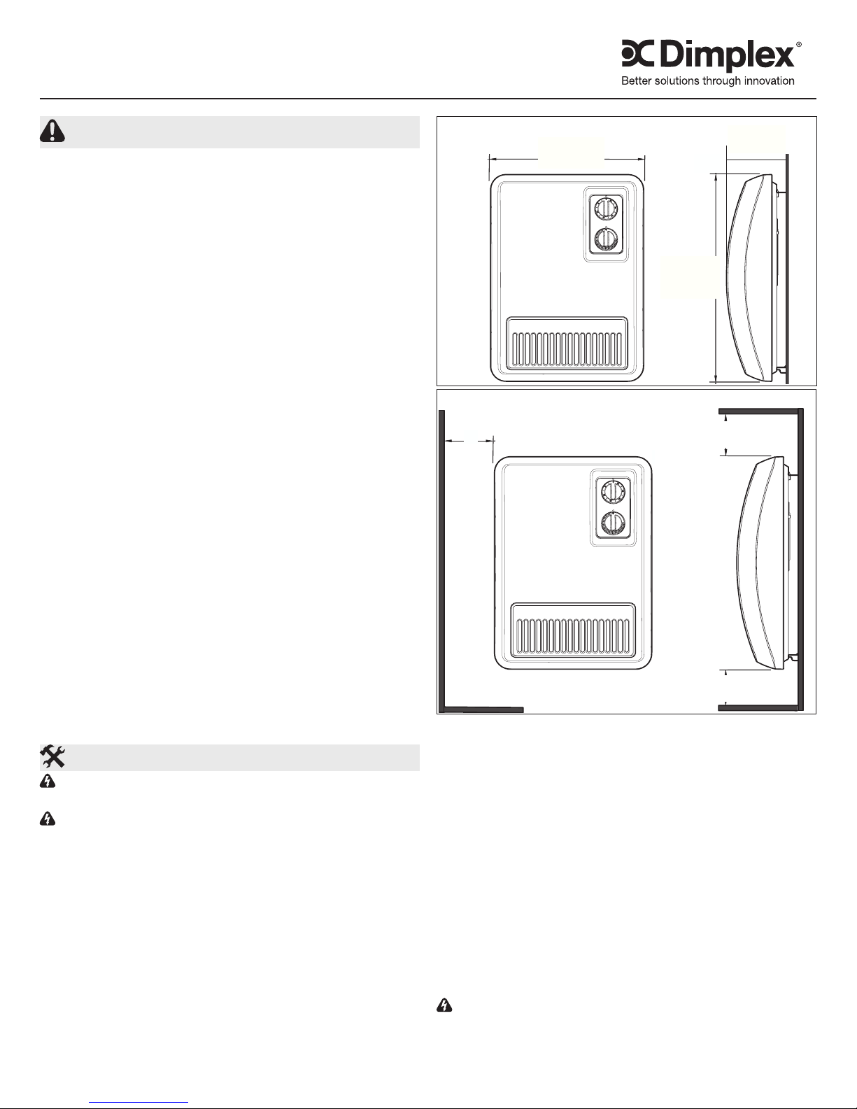
See Figure 1 for dimensions of the heater.
The heater must only be installed and operated on a
vertical wall as shown in Figure 2. Clearance from any
vertical surface must be no less than one (1) inch (25 mm),
clearance from any horizontal surface must be no less than
9¼ inches (230 mm) to the bottom of the heater and 12
inches (300 mm) to the top.
In addition, a minimum clearance of three (3) feet (900
mm) between inammable objects e.g. curtains, towels or
heat-sensitive plastics, and the front of the unit must be
maintained.
Figure 1
11¾”
(300 mm)
16”
(405 mm)
4¾”
(120 mm)
Figure 2
>1”
(25 mm)
>12”
(300 mm)
>9¼”
(230 mm)
Electrical Connection
Verify that the supply voltage is the same as that stated on
the heater (AC supply only).
This heater is designed for use on a 208/240V 60Hz AC
single-phase supply. Connection requires a supply wire
that must consist of two wires plus ground and have a rating
capable of handling all loads on the circuit.
Make all relevant electrical connections within an installed
junction box and ensure all wiring meets all local electrical
and building codes. Where local code requires the
disconnection of all ungrounded supply lines, a double pole
isolating switch must be tted to facilitate isolation.
Connection to the heater should be made using the provided
tted cable clamp assembly at the back of the heater to meet
local code requirements.
WARNING: Always use a qualied and licensed
electrician for all wiring and electrical connections. Improper
wiring could lead to a re hazard.
7209940100R02
Page 2
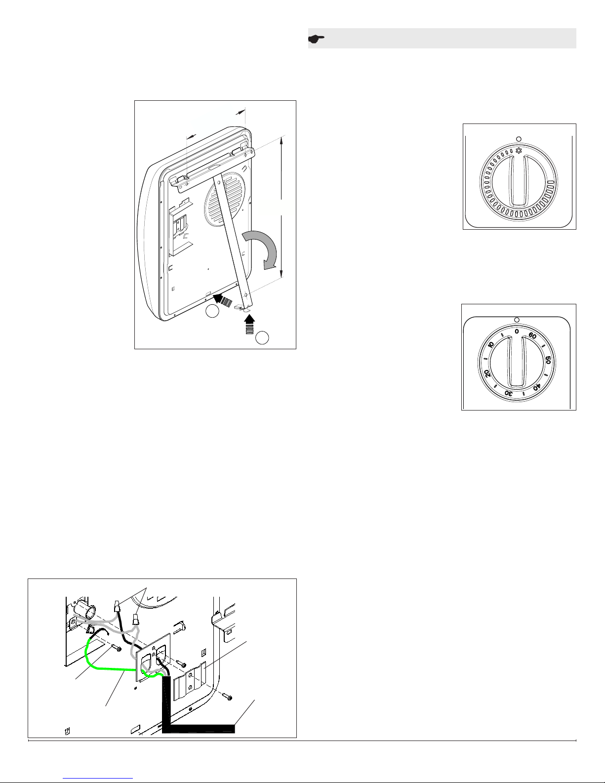
Mounting Instruction
A
B
308
190
The heater is supplied with a wall mount bracket, three 1.
(3) screws with wall plugs, and a cable clamp assembly.
Other or supplemental hardware should be used as
needed and as appropriate for the type of wall being
mounted to.
Unlock the wall 2.
bracket (Figure 3-A)
and remove from
the device.
Position wall 3.
bracket on wall,
and mark desired
position through
bracket holes.
Drill mounting holes 4.
for the wall bracket
and insert the wall
plugs.
Align the wall 5.
bracket and rmly
screw it onto the
wall.
Remove the large 6.
Phillips screw from
back of heater
holding the cable clamp in place (Figure 4). Set screw
and clamp plate aside.
Remove the smaller Phillips screw and larger metal plate 7.
to gain access to the heater’s wiring (Figure 4).
Make the L1 and L2 connections from power supply to the 8.
wires within the heater (wires will be labeled), using the
supplied wire connectors.
Connect ground wire from power supply to Ground Screw 9.
(Figure 4).
Reattach the large metal plate and screw removed in step 10.
2 allowing the cable to feed through.
Run cable over the large plate and clamp in place with the 11.
clamp plate and screw removed in step 1.
Align slots in back of heater with tabs on wall mount 12.
bracket and hang the device on the wall mount bracket.
Pivot down the heater and push into place (Figure 3-B).13.
Ensure that when in use, the airow is not obstructed.14.
Figure 4
Ground
Screw
Ground Wire
Figure 3
Wire Connectors
7½”
(190 mm)
Cable
Clamp
Plate
12”
(300 mm)
Power
Supply
Operation
Thermostat
The EF12 model is tted with an adjustable thermostat
allowing the room temperature to be controlled by adjusting
the setting accordingly. The thermostat has a minimum
setting, which can be used as a frost protection setting.
Provided that the controls are set to a heating function, the
heater will come on when the
surrounding temperature falls
to approximately 5˚ C (41˚ F).
Turn the thermostat knob
(Figure 5) to the highest position
to warm the room rapidly. When
the room temperature has
reached the desired level, turn
the thermostat knob back slowly
until the thermostat just clicks off. The heater will then
maintain the room temperature at the chosen level.
Should your heater fail to come on when the thermostat is at
a low setting, this may be due to the room temperature being
higher than the thermostat setting.
60-minute Timer
The EF12 model incorporates
a 60 minute delay timer and
thermostat. With the timer set
at ‘0’ the heater will operate at
1kW (on a 240 V supply) or
0.75kW (on a 208 V supply)
and low fan speed under
the control of the thermostat.
With the Timer in operation the heater will output 2kW (on
a 240 V supply) or 1.5kW (on a 208 V supply) and high fan
speed without thermostatic control.
Set the timer by turning the control knob clockwise until the
required operating time is indicated opposite the mark as
shown in Figure 6. The heater will operate at 2kW output (on
240 V supply) or 1.5kW (on 208 V supply) for the set period,
after which the output will reduce to 1 kW (on 240 V supply)
or 0.75kW (on 208 V supply). The timer setting may be
overridden at any time by returning the knob to ‘0’.
Protection Against Overheating
A thermal cutout will switch off the heater if for any reason
it overheats. Should the cutout operate, disconnect heater
from power supply and determine the reason for overheating.
Resolve the reason for overheating before attempting to use
the heater again. To reset the heater it is necessary to switch
off the power to the heater for several minutes.
Faults
If the heater does not give off heat, check the following
points:
• Has the thermostat been set to the desired temperature?
• Has the overheat protection been triggered? See
Protection Against Overheating section.
• Is the fuse in the fuse box switched on?
Figure 5
Figure 6
www.dimplex.com2
Page 3

If the fault cannot be corrected, please contact a specialist
electrical service center or else your nearest after-sales
service.
When the power line of this device is damaged, it must be
replaced by the manufacturer or after-sales service, or by a
similarly qualied person, in order to avoid risks.
To process your order, please state the production number
and manufacturing date of the device. This information is
listed on the back plate.
The device must only be repaired or manipulated by a skilled
electrician or the after-sales service.
Maintenance
Cleaning
The outside can be cleaned with a soft damp cloth and then
dried. Do not use abrasive cleaning powders or furniture
polish as this can damage the surface nish.
Warranty
The manufacturer warrants the heating elements and
components of the enclosed product against any defect
in material or workmanship for a period of two years.
In full satisfaction of any claims under this warranty the
manufacturer will repair or replace without charge in its
factory or in the eld as it alone may decide any parts which
in its operation are defective.
The manufacturer shall not be responsible for any
transportation or shipping costs in relation to such repair
or replacement except as specically assumed by it.
Misuse of this product or repairs by persons other than
the manufacturer’s authorized personnel without the
manufacturer’s written approval, will void this warranty.
This warranty is in lieu of all other warranties or conditions
whether expressed or implied including but not limited
to those of merchantability or tness for purpose, and
shall constitute the sole remedy of the purchaser and the
sole liability of the manufacturer in respect of the sale of
the product whether in the nature of breach or breach of
fundamental term or of negligence or otherwise.
The manufacturer shall not be liable for any special indirect
or consequential damages or for any damages resulting from
removal or replacement of a heater subject of a warranty
claim without the manufacturer’s authorization.
This warranty is transferable by the original consumer
purchaser of the product. Any claims under this warranty
must be submitted in writing to: Dimplex North America
Limited, 1367 Industrial Road, Cambridge Ontario, N1R 7G8,
Canada.
1367 Industrial Road Cambridge ON Canada N1R 7G8
1-888-346-7539 www.dimplex.com
In keeping with our policy of continuous product improvement, we reserve the right to make changes without notice.
© 2012 Dimplex North America Limited
3
 Loading...