

Page 1
Oil filled Radiators Models :
Model DYOF20 sho wn
UK Installation and Operating Instructions
DYOF15 and DYOF20
Model Specification
DYOF15 7 Fin , 1500W , Thermostat , N eon , 3 Heat S ettings ( 600/900/1500W).
DYOF20 9 Fin , 2000W , Thermostat , Neon , 3 Heat Settings (800/1200/2000W ).
IMPORTANT : THESE INSTRUCTIONS SHOULD BE READ CAREFULLY AND RETAINED FOR FUTURE REFERENCE
WARNING – THIS RADIATOR MUST ONLY BE OPERATED IN THE UPRIGHT POSITION WITH THE
CASTORS FITTED, AS DETAILED BELOW
Important Safety Advice This radiator compli es with stringent saf ety stan dards but to ensure efficient operation
SURFACES OF THE RADIATOR WILL BECOME HOT AND CONTACT WITH THESE AREAS
SHOULD BE AVOIDED, particularly between the fins.
The control panel area is designed to be cooler and allow safe operation of the controls at
all times.
If young childr en, the aged or infirm are likely to b e left in the vicinity of the heater, we
advise th at adequate precautions should be taken. We recommend that a guard be fitted
to ensure contact with the heater is avoided and objects cannot be inserted into the
product.
WARNING – DO NOT USE THIS RADIATOR IN THE IMMEDIATE SURROUNDINGS OF A
BATH, A SHOWER OR A SWIMM ING POOL.
WARNING – THIS RADIAT OR M UST NOT BE LOCAT ED IMM EDIATELY BELOW A FIXE D
SOCKET OUTLET.
This radiator must be used on an AC ~ supply only and the voltage marked on the heat er
must correspond with the supply voltage.
DO NOT USE the radiator if it has been dropped or damaged or the mains lead has been
damaged, until it has been examined by a qualified engineer.
DO ENSURE that the mains lead cannot be tripped over.
DO NOT operate the radiator with the mains lead overhanging the fins.
DO NOT COVER THE RADIATOR or place material or garments on it or between the fins.
Do not obstruct the air circulation around the radiator, for example with curtains or
furniture, as this could cause overheating and a fire risk. See ‘Positioning the Radiator’.
THIS RADIATOR CARRIES A WARNING ‘DO NOT COVER’ TO ALERT THE USER TO THE
RISK OF FIRE THAT EXISTS IF T HE RADIATOR IS ACCIDENTALY COVERED.
DO NOT USE THIS R ADIATOR WHEN IT IS LYING ON ITS SIDES. If the radiator is tipped
over, unplug i t and allow it to cool before standing it back up.
If the mains lead is damaged, it must be replaced by the manufacturer or its service agent
or a similarly qualified person in order to avoid a hazard.
The appliance is not intended for use by young childr en or infirmed persons without
supervision.
Young children should be supervi sed to ensure they do not play with the appliance.
For further information, please contact our guard supplier direct on Tel. No. 01603 667957,
or in case of difficulty or for further advice contact the Customer Helpline.
Electrical connections
WARNING : T HIS APPLIANCE MUST BE EARTHE D.
This heater must be used on an
AC ~ supply only and the voltage marked on the heater must
correspond to the supply voltage. If fitting a 13 amp plug, a 13 amp fuse approved by ASTA to
BS 1362 must b e used. If any other type of plu g is used, a 15 amp fuse must be fitted in the
plug, the adaptor, or at the distribution boar d.
IMPORTANT - The wires in the mains lead are coloured in acc ordance with the following code:
GREEN and YELLOW - EARTH
BLUE NEUTRAL
BROWN LIVE
Connect the GREEN AND YELLOW wire to the terminal marked ‘E’ or by the earth symbol
or coloured GREEN or GREEN AND YELLOW.
Connect the BRO WN wire to the terminal marked ‘L’ or coloured RED.
Connect the BLUE wire to the terminal marked ‘N’ or coloured BLACK.
This appliance must only be used on A.C. mains supply of 230-240 Volts~.
,
08/18777/2 Issue 2
Page 2
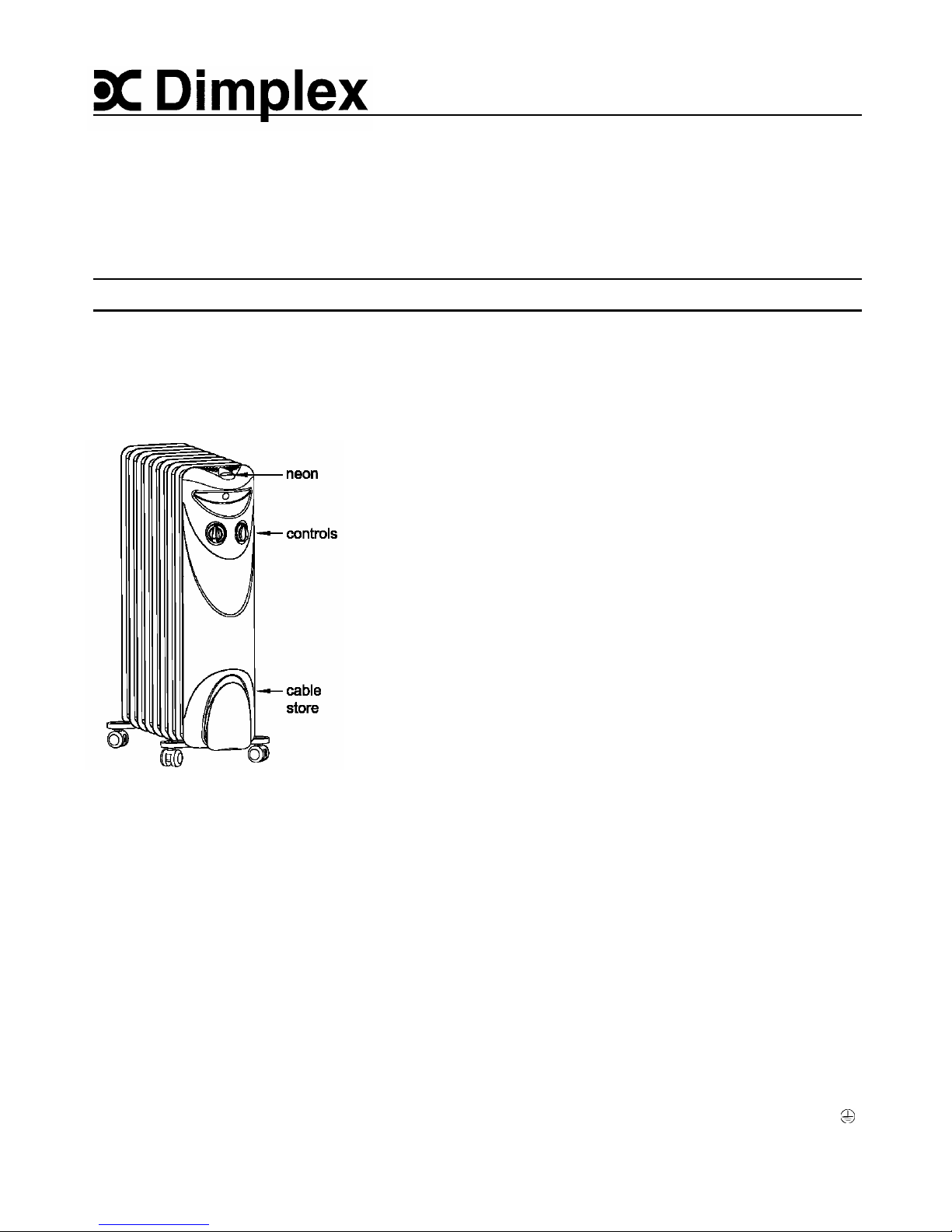
s - DYOF15 & DYOF20
hermostat
ob
n
x
eat selector
tch
Model
Thermostat control (see Fig. 3)
T H
DYOF15 o – Of f I - 600W, I I - 900W, I I I - 1500W -
DYOF20 o – Of f I - 800W, I I - 1200W, I I I - 2000W
kn swi
On all models, the radiator is OFF when the heat switch is s et to position ‘O’
mi
Heat control (see Fig. 3)
The heat switch provides a choice of heat outputs :
ma
Heat switch settings
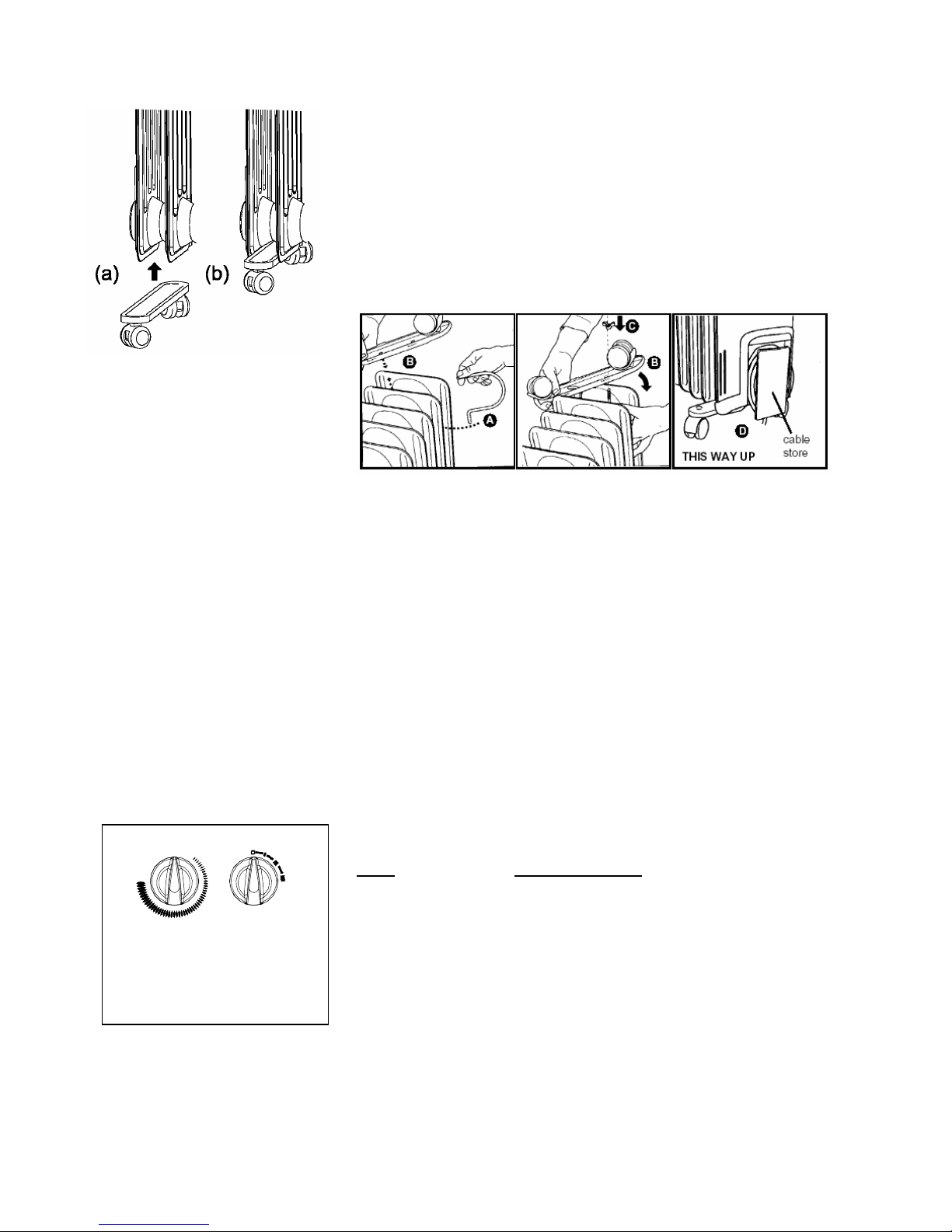
Fitting the castors Remove the carton containing the castor ass emblies from the packing.
The castors must be fitted between the fins ( as shown on ‘ a’ and ‘b’ in Fig 1)
.
The heat output is controlled by the thermostat, according to the room temperature.
Turn the knob to max. setting. When the room is warm enough, r educe the setting slowly until
Fig. 3 the radiat or just clicks off.
Fit the c astors to the stub axles by app lying hand pressure until eac h cast or clicks into position.
Note that the c astors are designed to be a tight fit on the axles but will rotate in us e.
IMPORTANT – ENSURE THAT THE CASTORS ARE FITTED TO THE BASE OF THE
RADIATOR SO THAT, WHEN IN USE, THE CONTROLS ARE AT THE TOP AND THE CABLE
STORAGE AT THE BOTTOM OF THE CONTROL PANEL – see Fig. 2.
The radiator will now cycle on and off to maintai n your sel ected room temper ature.
NOTE : If the radiator does not c ome on when the thermostat is on a low setting, this is normally
because the room is warmer than the thermostat setting and is not a fault.
If the thermostat is set to min. and a heat setting is selected, the thermostat will turn the radiator
on and off to maintain a low temperature to help pr otect against f rosty conditions.
Turn the radiat or upside down on a carpet or other s oft surf ace t o avoid damage.
Warning : The radiator is heavy – ensur e that it is supported to prevent it from toppling. Ask a
second person to help with this if necessary. Locate the wire clamps and remove the plastic
straps and winged nuts (see ‘C’ bel ow).
Insert the non-threaded end of the wire clamp ‘A’ into one of the two holes in the cast or plate ‘B’
as shown in Fig. 2, at the s ame ti me tilti ng the opposite end of the plate slightly. Lower the c astor
plate and ins ert the thr eaded end of the clamp thr ough the fins and over the boss and in to the
other hole in the castor plate. Place the winged nut ‘C’ on the thread and tighten it securely
.
Fig. 1
Fig. 2
Lift the radiator clear of the floor, then tur n it back upright and stand it on its castors as shown in
Fig. 2 ‘D’. It is now ready for use.
Positioning the radiator
Always ensure that the radiator is stood on a firm, level base near to, but not directl y beneath, a
suitable fixed socket outlet.
Unwind the mains lead fully from the cable store at the base of the control panel before
plugging in the radiator. DO NOT pull the radiator along by the mains lead.
Ensure that curt ains and furnit ure are not closer than 1 metre (3’) from the chosen position, as
this would create a potential fire hazard.
Ensure that th ere is at least 300mm ( 1’) above the radiator of unobstructed space
.
Before switching on
Ensure that all packing items are removed (read any warning labels carefully) and that all
warnings and instructions have been r ead carefully and followed.
Operation
When you are certain that you have completed the above, plug in and switc h on at the wall
socket. T he neon will glow all the time that the radiator is switched on
.
Please Not e – We recommend that you open a window to ventilat e the room when using the
heater f or the first time.
Model
Page 3

Storage
If the radiator is not required f or long periods, f or example during the summer, it should be stored
in dry place and prefer ably cover ed to prevent the accumulation of dust and dirt.
The mains lead c an be wound around the cable stor e at the bottom of the control panel , ensur ing
that the plug does not trail on the floor.
Cleaning WARNING – ALWAYS DISCONNECT FROM THE POWER SUPPLY AND ALLOW THE
RADIATOR TO COOL BEFORE CLEANING.
Do not use detergents, abrasive c leaning powder or polis h of any kind on the body of the
radiator, as th ese can damage the finish.
Wipe the radiator with a dry cloth to remove dust and a damp cloth (not wet) to clean off st ains.
Be careful not to allow moisture into the controls area.
After Sales Service
This heater is filled with a precise quantit y of special oil. Repairs requiring opening of the oil
container are only to be made by the manuf acturer or his service agent who should be contacted
if there is an oil leakage.
Regulations conc erning the disposal of oil when scrapping the appliance have to be followed.
Your appliance is guaranteed for three years from the date of purchase. We undertake to repair
or exchange free of charge within this p eriod, any part f ound to be defective due to a
manufacturing f ault.
Your rights under this guarantee ar e additional to your statutory rights, whic h in turn are not
affected by this guarantee.
Please retain your receipt as proof of purchase.
Page 4

The pr oduct complies with the European Safety Standards EN60335-2-30 and the European Standard Electromagnetic C ompatibility
(EMC) EN550 14, EN60555-2 and EN 60555-3 which cover the essential requirements of EEC Directives 73/23 and 89/336
Glen Dimplex U K Limited UK cust omer help line ( 8.00AM – 6.00PM Mon-Fri; 8.30A M-1.00PM S at)
Millbrook Hous e
Grange Drive Customer Services: Tel. 0870 7270101
Hedge End Fax. 0870 7270102
Southampton e-mail customer.s ervic es@glen dimplex.com
Hampshire. SO30 2DF Republic of Ireland Tel. 01 8424833
 Loading...