

Page 1
Dimplex Low Wattage Panel Heaters
Models: DYLP40,
DYLP80,
DYLP80TI
Installation and Operating Instructions
INDLUKDYBQ Issue 1
Dimensions
(millimetres)
Models Specification
DYLP40 400W Neon Heat Switch
DYLP80 800W Neon Heat Switch
DYLP80TI 800W Neon Heat Switch / 24 Hour Timer
THESE INSTRUCTIONS SHOULD BE READ CAREFULLY AND RETAINED FOR FUTURE REFERENCE
IMPORTANT SAFETY ADVICE
WARNING –THIS APPLIANCE MUST NOT BE USED IN A BA THROOM
WARNING - DO NOT USE THIS HEA TER IN THE IMMEDIA TE
SURROUNDINGS OF A BATH, A SHOWER OR A SWIMMING POOL
.
WARNING – THIS HEA TER MUST NOT BE LOCA TED IMMEDIA TEL Y
BELOW A FIXED SOCKET OUTLET.
DO NOT USE THE HEATER UNTIL THE FEET OR W ALL BRACKETS
ARE FITTED CORRECTL Y .
FOLLOW these instructions carefully.
The heater carries a warning ‘DO NOT COVER’ to alert the
user to the risk of fire that exists if the heater is accidentally
covered.
Model DYLP80TI can be set to switch on automatically
.
Remember to observe all safety warnings at all times.
If young children, the aged or infirm are likely to be left in the
vicinity of the heater, we advise that adequate precautions
should be taken. We recommend a guard be fitted to ensure
contact with the heater is avoided and objects cannot be
inserted into the product.
If the mains lead is damaged, it must be replaced by the
manufacturer or its service agent or a similarly qualified
person in order to avoid a hazard.
For further information, please contact our guard supplier
direct on Tel. No. 01603 667957, or in case of difficulty or for
further advice contact the Customer Helpline.
If the socket outlets in your home are not of the 13 amp BS1363 type
they will not accept the plug connected to this heater, therefore cut off
the plug. When cut off this plug can constitute a shock hazard if inserted
into a socket outlet. It must therefore be disposed of safely.
Before wiring the appropriate plug please note that the wires in this
mains lead are coloured in accordance with the following code.
GREEN/YELLOW - EARTH
BLUE - NEUTRAL
BROWN - LIVE
Connect the Green/Yellow wire to the terminal marked E or the earth symbol
G
or coloured Green or Green/Yellow.
Connect the Brown wire to the terminal marked L or coloured Red.
Connect the Blue wire to the terminal marked N or coloured Black.
DO NOT connect the Brown (Live) or the Blue (Neutral) wires to the
Earth terminal of your 13 amp plug. If the terminals of the plug are
unmarked or you are in any doubt, consult a qualified electrician.
CAUTION: If you use this heater in conjunction with a thermal control,
programme controller, timer or any other device which switches the
heater on automatically observe all safety warnings at all times.
Electrical Connection
WARNING THIS APPLIANCE MUST BE EARTHED
POSITIONING THE HEATER
Select the position for the heater ensuring there is clearance
from any furniture and fittings of at least 150mm above the
heater, 50mm below (wall mounted) and 25mm each side.
Curtains must not be closer than 150mm from the top of the
heater.
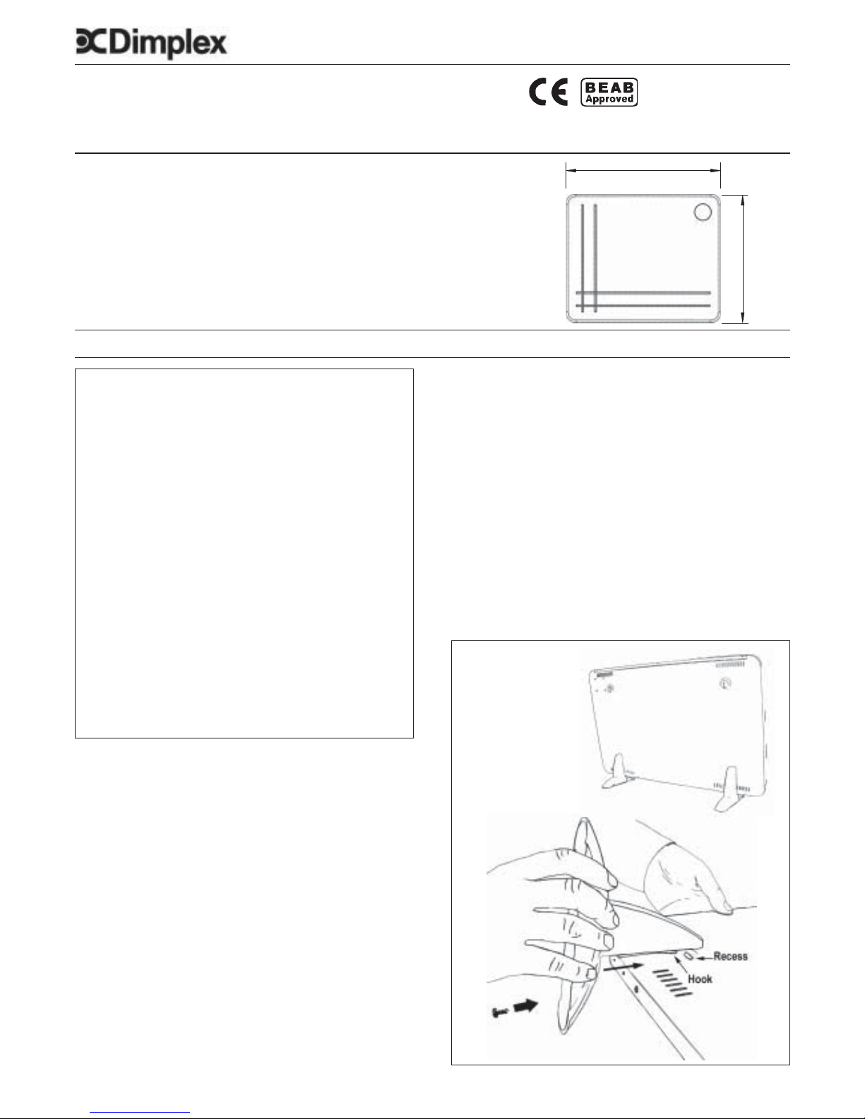
Free Standing Operation (Fig. 1)
NEVER USE THE HEATER FREE STANDING WITHOUT THE FEET
FITTED.
1. Lay the heater on its front.
2. Remove the two socket head screws from the base of the
heater using the hexagon key supplied.
3. Place feet over base of heater, align holes and engage hook
on foot into the recess on the back of the heater.
(See Fig. 1).
4. Replace the screws but do not overtighten.
Fig. 1
600 mm - 400W
800 mm - 800W
500 mm
Rear View
Page 2
3. Drill the wall at the three marked positions and fit the wall
plugs.
Ensure template has been removed.
4. Fix two No. 8 screws to the top two holes leaving 3mm of the
screw exposed. Hang the heater on the screws.
5. Fit the bottom bracket, found in the fixing kit, in the slot at the
base of the heater and screw the bracket to the wall.
Test that the heater is now securely fixed to the wall.
Operation
IMPORT ANT - OBJECTS OR CLOTHING MUST NOT BE PLACED ON THIS HEATER.
Before using the heater ensure that all warnings and instructions have been read carefully .
OPERATION
Models DYLP40, DYLP80, DYLP80TI
Turn the heater on using the switch on the right side of the heater
- the switch will be illuminated.
MODEL WITH TIMER - (see Fig. 3)
DYLP80TI
The switch on the side of the heater turns the heater on.
Note: This switch must be in the “on” position before the heater
will operate.
Wall Mounted Operation (See Fig. 2)
WARNING: This heater must not be locate
d
immediately below a fixed socket outlet.
The plug must be accessible after heater installatio
n.
Suggested Fixings
SOLID BRICK/BLOCK: No. 8 Rawlplug inserts, 6mm drill bit.
PLASTERBOARD - If possible locate studding and use No. 8
woodscrews directly into the wood, otherwise M5 rawlplug intersets
are suitable.
NOTE: FOR OTHER WALL TYPES (e.g. T imber frame and hollow
concrete) SEEK SPECIALIST ADVICE.
1. Select the position for the heater ensuring there is
clearance from any furniture and fittings of at least 150mm
above the heater, 50mm below and 25mm each side.
Curtains must not be closer than 150mm from the top of the
heater.
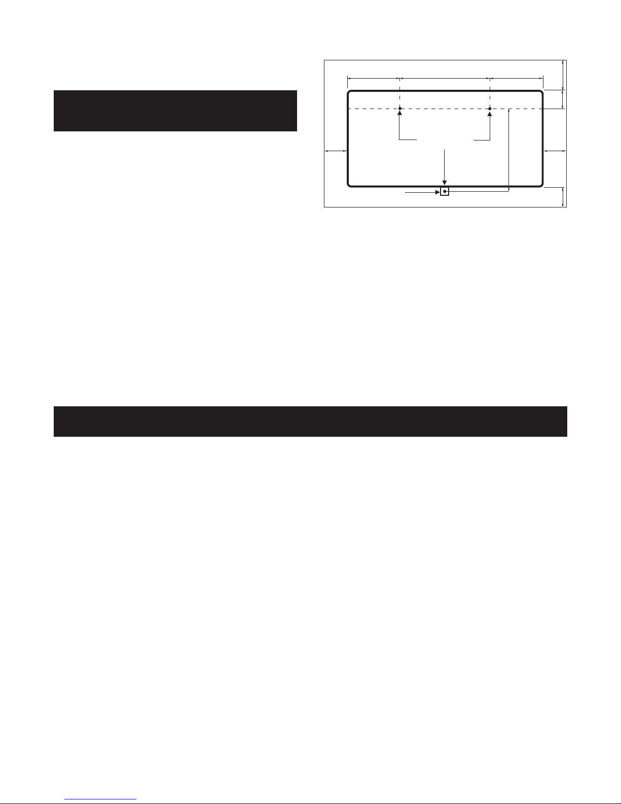
2. Position the drilling template provided on the wall ensuring it
is level. Mark the position of the relevant holes on the wall at
the edge of template. Before drilling check that the distance
between the hole centres is correct, 340mm for the 400W
Model and 540mm for 800W models (see Fig. 2).
Digital Timer Operation
IMPORTANT Remember to observe all safety warnings when
operating the heater on auto setting unattended or attended.
The timer allows you to select ‘MANUAL ON’ , ‘AUTO’ or’ MANUAL
OFF’ operation mode by pressing the Input / Output button marked
‘I/O’ until the required mode appears at the bottom of the timer
display.
‘MANUAL ON’ mode allows power to the heater uninterrupted by
the timer settings. The heat selector switch will control the output.
‘MANUAL OFF’ mode switches off all heater operation completely.
‘AUTO’ mode allows the low wattage panel heater to switch ON
and OFF according to the timer settings (see ‘Setting Programs’
section below).
12/24 Hour Mode Either 12 or 24 hour modes can be used.
Press the S (Set) and P (Program) buttons simultaneously to switch
between 12 and 24 Hour mode.
Initial Operation (Fig. 3)
For initial use, plug the timer into a regular household power point
and turn the power on. Clear all current information by pressing the
R button with a sharp object such as a pencil. The timer is now
ready to be set up for use.
Installation
The Fixing Kit should contain: 1 Drilling Template, 3 Screws, 3
Rawlplugs, 1 Mounting Bracket and 1 Hexagon Key.
130mm
340mm - 400W
540mm - 800W
95mm
150mm
50mm
Fig. 2
420mm
25mm 25mm
130mm
Drilling Holes
Bracket
Page 3

9) Mo, T u, We, Th, Fr
10) Sa, Su
11) Mo, T u, We, Th, Fr , Sa
12) Mo, We , Fri
13) T u, Th, Sa
14) Mo, T u, We
15) Th, Fri, Sa
16) Mo, We, Fr , Su
Safety - Overheat Protection
For your safety the front panel temperature is regulated by a
thermal limit thermostat.
Setting Current Time
1. Press the S (Set) button and keep pressed while pressing the
D (Day) button until the actual day is displayed. Continue by
pressing H (Hour) or M (Minute) button until the current hour or
minute is displayed. When resetting, the buttons D, H or M can
be held down for rapid forward counting.
2. Release both buttons. The day and time will now be set.
3. To reset incorrect time, repeat previous steps.
Summertime Function
Summertime function is very useful for areas with summertime
system, the timer can quickly and easily be changed to operate
in SUMMER time mode i.e. one hour ahead, and back again as
follows;
1. Press the S (Set) and I/O (Input/Output) buttons simultaneously .
The LCD will show ‘SUMMER’. The clock will switch ahead one
hour.
2. Press the buttons together again and the clock will switch back
again one hour to standard time & ‘SUMMER’ will no longer be
displayed .
Setting Programs
Once the correct time is set , a total of 8 ON/OFF time programs can
be set for AUTO operation. These can be set to operate on any of 16
different combinations of individual days or groups of days
depending on your individual choice. To program the timer follow
the following setting instructions;
1. To select the first of your 8 ON/OFF programs simply press
the P (Program) button once , the program is then input as
follows ;
2. You first select one of the 16 different combinations of
individual days or groups of days you wish to set this
program for. Continue to press and release the D (Day)
button to go through the choices until the day or blocks of
days you require appears along the top of the timer display
then stop pressing , the 16 different combinations that can
be chosen are as follows;
1) Mo
2) Tu
3) We
4) Th
5) Fr
6) Sa
7) Su
8) Mo, Tu, We, Th, Fr, Sa, Su
3. Now set the time by pressing the H (Hour) button and then
M (Minute) button until the desired time setting is displayed.
4. Press the P (Program) button again to finish the first ON
setting and enter into the first OFF setting. By repeating
steps ‘2’ & ‘3’ above you can now complete the input of the
first OFF setting.
5. Press the P (Program) button again to finish the first ON/
OFF program and enter into the 2nd ON setting. Repeat
steps ‘2’ , ‘3’ and ‘4’ to complete this program , then press
P again and repeat cycle as necessary.
6. Once you have completed the number of ON/OFF programs
you require (up to a maximum of 8) , press the S (Set)
button to save the settings and the timer is now ready to
operate in Auto mode.
EXAMPLE : To set Timer ON at 18:15 and Timer OFF at 22:15
everyday
a) Press P and LCD displays ‘1_ON’
b) Press D until LCD displays ‘MO, TU, WE, TH, FR, SA, SU’
c) Press H until LCD displays ‘6:00PM’ or ’18:00’
d) Press M until LCD displays ‘6:15PM’ or ’18:15’
e) Press P and LCD displays ‘1_OFF’
f) Repeat c) and d) until LCD displays ‘10:15PM or 22:15’
g) Press S and the program is saved and the current time
display returns.
TIP : When verifying your programs ensure that the settings do
not overlap, especially when using the block option.
TIP : To clear a section in a Program, press the C (Clear) button.
To reactivate this section press the C button again.
Notes on switching between Manual ON/Auto/Manual OFF
1. Pressing I/O (Input/Output) button allows you to change
between
Manual ON / Auto / Manual OFF modes , current mode will
be displayed on the bottom of the LCD display.
2. In Manual ON or Manual OFF mode, the Timer operates but
the programme settings are inactive.
3. When the mode is turned from Manual ON to Auto, the
Timer mode will remain ON until the next programmed
timer off setting is reached.
4. When the mode is turned from Manual OFF to Auto the
timer mode will remain OFF until the next programmed
timer ON setting is reached.
Note - Timer Memory Back Up Batteries - Once the heater has
been left plugged in with the socket switched on for at least 12
hours the timers memory back up batteries will be fully charged.
Once the timer batteries are fully charged , if there is a power
cut or if the heater is disconnected from the mains for less than
100 hours , then the timer will continue to keep time & the
settings in the memory will remain intact.
If however the timer back up batteries have not been charged
fully, or if the heater is deprived of power for longer than 100
hours, then the time and the programme settings are likely to
be lost and you may therefore need to reset the time and the
programme before using the Auto mode again.
Fig. 3
Page 4

Glen Dimplex Millbrook House
(UK) Limited Grange Drive
Hedge End
Southampton
Hampshire SO30 2DF
UK customer helpline (8.00AM - 6.00PM Mon-Fri; 8.30AM-1.00PM Sat)
Customer Help Line T e l: 0870 7270 101
Fax: 0870 7270 102
e-mail: customer.services@glendimplex.com
Republic of Ireland Tel: 01 842 4833
Cleaning
WARNING – ALWAYS DISCONNECT FROM THE POWER
SUPPLY BEFORE CLEANING THE HEATER.
Do not use detergents, abrasive cleaning powder or polish of
any kind on the body of the heater.
Allow the heater to cool, then wipe with a dry cloth to remove
dust and a damp cloth (not wet) to clean off stains. Be careful not
to allow moisture into the heater.
After Sales Service
Your appliance is guaranteed for three years from the date of
purchase. We undertake to repair or exchange free of charge
within this period, any part found to be defective due to a
manufacturing fault. Your rights under this guarantee are
additional to your statutory rights, which in turn are not affected
by this guarantee. Please retain receipt as proof of purchase.
The product complies with the European Safety Standards EN60335-2-30 and the European S tandard Electromagnetic Compatibility
(EMC) EN55014, EN60555-2 and EN60555-3 which cover the essential requirements of EEC Directives 73/23 and 89/336
 Loading...