

Dimplex DXLWP400TS, DXLWP400TiE7, DXLWP800TiE7, DXLWP800TS, DXLWP800TiE7B Installation And Operating Instructions Manual
Page 1

08/54231/0 Issue 1
The product complies with the European Safety Standards EN60335:2-30
As with all portable heating appliances: This product is suitable only for well insulated spaces or occasional use.
Low Wattage Panel Heater
DXLWP400TS, DXLWP800TS, DXLWP400TiE7, DXLWP800TiE7 & DXLWP800TiE7B
Designed to provide gentle background heating, to take the chill o a room. Ideally to be used with a principal
source of heating.
Page 2

Installation and Operating Instructions
CAUTION: Some parts of this product can
become very hot and cause burns. Particular
attention has to be given where children and
vulnerable people are present.
IMPORTANT: Avoid use of an extension cord
because the extension cord may overheat and
cause risk of re.
IMPORTANT: The wall bracket or feet supplied
with the appliance must be used.
DO NOT use this heater if it has been
dropped
DO NOT use if there are visible signs of
damage to the heater
Use this heater on a horizontal and stable
surface, or x it to the wall as applicable.
WARNING: Servicing and product repairs
should only be undertaken by the manufacturers
approved service agent or a similarly qualied
person, using only exact manufacturer approved
spare parts.
WARNING: To reduce risk of re, keep
textiles, curtains, or any other ammable
material a minimum distance of 1m from the
air outlet
This instruction leaet belongs to the appliance
and must be kept in a safe place. If changing
owners, the leaet must be surrendered to the
new owner.
The heater must be on a at stable surface
when in use.
ELECTRICAL CONNECTION
WARNING THIS APPLIANCE MUST BE EARTHED
If the socket outlets in your home are not of the 13 amp
BS1363 type they will not accept the plug connected to this
heater, therefore cut o the plug. When cut o this plug can
constitute a shock hazard if inserted into a socket outlet. It
must therefore be disposed of safely.
IMPORTANT: The wires in this mains lead are coloured in
accordance with the following code:
BLUE: NEUTRAL
BROWN: LIVE
GREEN & YELLOW: EARTH
As the colours of the wires in the mains lead may not
correspond with the coloured markings in your plug, proceed
as follows:
Connect the BROWN wire to the terminal marked ‘L’ or
coloured RED. Connect the BLUE wire to the terminal marked
‘N’ or coloured BLACK. Note: ‘L’ or ‘N’ must not be connected
to the EARTH terminal marked ‘E’ or ‘ ’ or coloured GREEN
or GREEN AND YELLOW. If in doubt, consult your electrician.
IMPORTANT: THESE INSTRUCTIONS SHOULD BE READ CAREFULLY BEFORE USE AND RETAINED FOR FUTURE REFERENCE
IMPORTANT SAFETY ADVICE
DO NOT use the heater in the immediate
surroundings of a bath, a shower or a swimming
pool.
DO NOT place the heater directly below a xed
socket outlet.
The socket-outlet must be accessible at all times
to enable the mains plug to be disconnected as
quickly as possible.
DO NOT cover the product.
DO NOT use this heater in small rooms when
they are occupied by persons not capable of
leaving the room on their own, unless constant
supervision is provided.
IMPORTANT: If the mains lead of this appliance
is damaged, it must be replaced by the
manufacturer or its service agent or a similarly
qualied person in order to avoid a hazard.
WARNING: In order to avoid a hazard due to
inadvertent resetting of the thermal cut-out,
this appliance must not be supplied through
an external switching device, such as a timer, or
connected to a circuit that is regularly switched
on and o by the utility.
This appliance can be used by children aged from
8 years and above and persons with reduced
physical, sensory or mental capabilities or lack of
experience or knowledge if they have been given
supervision or instruction concerning the use of
the appliance in a safe way and understand the
hazards involved. Children shall not play with the
appliance. Cleaning and user maintenance shall
not be made by children without supervision.
Children of less than 3 years should be kept away
unless continuously supervised.
Children aged from 3 years and less than 8 years
shall only switch on/o the appliance provided
that it has been placed or installed in its intended
normal operating position and they have been
given supervision or instruction concerning
the use of the appliance in a safe way and
understand the hazards involved. Children aged
from 3 years and less than 8 years shall not plug
in, regulate and clean the appliance or perform
user maintenance.
The heater carries a warning symbol
to alert the user to the risk of re that
exists if the heater is accidentally
covered
Page 3
Positioning the Heater
Select the position for the heater ensuring there
is clearance from any furniture and ttings of at
least 150mm above the heater, 50mm below (wall
mounted), 25mm each side and 300mm from the
front panel. Curtains must not be closer than
150mm from the top and/or sides of the heater.
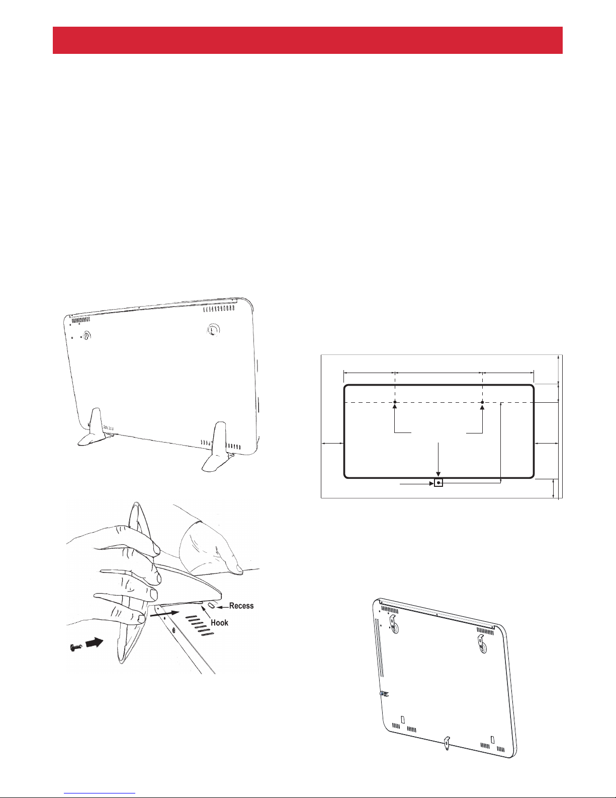
Free Standing Operation
NEVER USE THE HEATER FREE STANDING
WITHOUT THE FEET FITTED (FEET ARE PACKED
SEPARATELY IN CARTON).
1. Lay the heater on its front.
2. Remove the two star head screws from the
base of the heater using an x-head screwdriver.
3. Place feet over base of heater, align holes and
engage hook on foot into the recess on the back of
the heater - (see Fig below)
4. Replace the screws but do not over tighten.
Please Note: Although this heater is manufactured
to comply with the relevant safety standards,
certain types of carpets could become discoloured
by the temperatures under a portable heater. If you
are concerned about this, we recommend that you
contact the carpet manufacturer for guidance.
Alternatively, either stand the heater on a suitable
base to shield the carpet or wall mount it.
Installation
The xing kit should contain: 1 drilling template, 3
screws, 3 rawlplugs and 3 mounting brackets.
Wall Mounted Operation - Timer Models only
Suggested Fixings:
SOLID BRICK/BLOCK: No. 8 Rawlplug inserts, 6mm
drill bit.
PLASTERBOARD: If possible locate studding and
use No. 8 woodscrews directly into the wood, otherwise M5 rawlplug intersets are suitable.
NOTE: FOR OTHER WALL TYPES (e.g. Timber frame
and hollow concrete) SEEK SPECIALIST ADVICE.
1. Select the position for the heater ensuring there is
clearance from any furniture and ttings of at least
150mm above the heater, 50mm below, 25mm each
side and 300mm from the front panel. Curtains
mustnot be closer than 150mm from the top
and/or sides of the heater.
2. Select a suitable position on a wall, near to a
mains power socket, Fix the two top retaining
brackets to the wall, using suitable xings,the
distance between the hole centres is correct,
340mm for 400W Models and 540mm for
800W models (see Fig below).
3. Drill the wall at the three marked positions and t
the wall plugs.
Ensure template has been removed.
4. Locate the heater on the top brackets and
allow it to hang in place. Fit the bottom bracket
into the slot in the heater and then x it to the wall.
Test that the heater is now securely xed to the
wall.
130mm
340mm - 400W
540mm - 800W
62mm
150mm
50mm
446mm
25mm 25mm
130mm
Drilling Holes
Bracket
Page 4

Models
Model Name Description
DXLWP400TiE7 400W Panel heater with
Electronic thermostat &
Timer
DXLWP800TiE7 800W Panel heater with
Electronic thermostat &
Timer
DXLWP800TiE7B 800W Panel heater with
Electronic thermostat &
Timer-Black
DXLWP400TS 400W Panel heater
with Electro mechanical
thermostat
DXLWP800TS 800W Panel heater
with Electro mechanical
thermostat
IMPORTANT - OBJECTS OR CLOTHING
MUST NOT BE PLACED ON THIS HEATER.
NOTE - This product is suitable for background
heating only.
Before using the heater ensure that all warnings
and instructions have been read carefully.
Models with Thermostat Dial only– DXLWP400TS
& DXLWP800TS
DXLWP400TS & DXLWP800TS models are tted
with an adjustable thermostat allowing the background temperature to be controlled by adjusting
the setting accordingly. The thermostat has a
minimum setting, which can be used as a guard
against frost. Provided that the controls are set to
a heating function i.e switched ON, the heater will
come on when the surrounding temperature falls
to approximately 5˚ C (41˚ F). Turn the thermostat
knob to the highest position to warm the room to
desired level. When the room temperature has
reached the desired level, turn the thermostat knob
back slowly until the thermostat just clicks o. The
heater will then maintain the background
temperature at the chosen level.
NOTE - Should your heater fail to come on when the
thermostat is at a low setting, this may be due
to the room temperature being higher than the
thermostat setting.
Models with Timer– DXLWP400TiE7,
DXLWP800TiE7 & DXLWP800TiE7B
DXLWP400TiE7 - 1 Switch
The switch on the side of the heater turns the
heater on. Note: This switch must be in the “on”
position before the heater will operate.
DXLWP800TiE7 & DXLWP800TiE7B - 2 Switches
The two switches on the side of the heater control
the amount of heat available as described below,
NOTE: At least one switch must be in the ‘On’
position before the heater will operate.
Position O - OFF
Position I - ON
Both switches in Position I indicates maximum output.
Top switch only in Position I indicates 500W output
on 800W model.
Bottom switch only in Position I indicates 300W
output on 800W model
Timer unit
The heating device is equipped with a congurable
electronic control, consisting of a display, a red LED
and ve keys.
The control unit is located on the front panel of the
heater.
The set functions and values are shown on the
display.
The LED lights up red when heating ON.
The switch on the side of the heater turns the
heater on. Note: This switch must be in the
“on” position before the heater will operate.
DXLWP400TS & DXLWP800TS - 1 Switch
F
COPY
BLK
OFF
ON
P
DLY
AUTO
ADVANCE
MANUAL
ON
M
T
W
T
S
S
OFF
Save entry
Set program
Select operating mode
Value down/up
Weekday
Program no. (1 - 4)
Manual operation
Automatic operation
Advance
Copy
Setting the time
Key lock
Heating operation on
Time block on
Heating operation off
Time block off
F
COPY
OFF
ON
P
AUTO
ADVANCE
MANUAL
ON
M
T
W
T
S
S
OFF
Control Description - Timer Models
Page 5

.
or time.
Auto/Timer operation
Up to four heating programs (ON/OFF) can be
set for each weekday. A room temperature can
be specied for each heating program.
AUTO appears on the display.
Manual operation
Manual specication of the room temperature.
MANUAL ON or MANUAL OFF appears on the
display.
Advance
Switch to the next program item in automatic
mode.
ADVANCE appears on the display.
NOTE
In manual operation (MANUAL ON), the desired
temperature can be specied with the +/- keys.
In Auto/timer mode, the desired temperature setting
is only carried out for the current running time
program.
• Use the + / - keys to set the hours. Press the
ENTER key. The minutes display ashes.
• Use the + / - keys to set the minutes. Press
the ENTER key. The weekday ashes.
• Use the + / - keys to set the weekday. Press
the ENTER key. The CLOCK symbol disappears.
Setting is complete
Pressing the MODE key switches the operating
mode between MANUAL ON, MANUAL OFF
and AUTO/TIMER.
Manual ON
• Manual heating operation switched on.
• Display alternates between room temperature
setting and the current time.
• Room temperature is set with +/-.
Manual OFF
• Heating operation switched o.
• The current time is displayed.
• Room temperature cannot be set.
NOTE
In MANUAL OFF operating mode, frost protection
takes place. If the room temperature is
5° C or less, the heating device is switched on
automatically.
Auto/Timer Mode
• Auto/Timer mode (week program) activated.
• Display alternates between room temperature
setting and the current time.
• Heating operation takes place in the
specied time blocks for ON and OFF.
• Room temperature is set with +/-.
No times blocks are specied at the factory.
These must be dened by the user as required.
NOTE
In time block OFF, frost protection is set at the
factory. If the room temperature is 5° C or less, the
heating device is switched on automatically.
F
ON
M
T
W
T
S
S
MANUAL
ON
Key functions
MODE
• Auto/Timer mode (week program)
• Manual operation ON
• Manual operation OFF
ENTER
Save entry.
PROG
Week program, set clock.
Keys +/-
Used to navigate through the menu and to
change the setting values e.g desired temperature
F
ON
M
T
W
T
S
S
MANUAL
ON
The time and day are set with the following steps:
• Press and hold the PROG key for three seconds.
The clock symbol appears. The hours display
ashes.
Operating Modes
Selecting the Desired Temperature
Setting the Time and Week Day
Page 6

Auto/Timer mode - Week Program
NOTE
For extended operation, it is advisable to use the AUTO/
TIMER operating mode to reduce the operating costs.
Four times blocks are available per day. These can
be adapted individually for each weekday.
• Select AUTO operating mode by pressing the
MODE button.
• Press the PROG key. WEEKDAY display ashes.
Order from top to bottom:
M = Monday, F = Friday,
T = Tuesday, S = Saturday,
W = Wednesday, S = Sunday.
T = Thursday,
• Use the +/- keys to set the weekday.
F
M
T
W
T
S
S
Setting time block ON
• Press the ENTER key. P1 (program 1) and ON
appears, The hours display ashes.
• Use the +/- keys to set the hours. Press the
ENTER key. The minutes display ashes.
• Use +/- to set minutes (in 10 minute increments).
Setting time block OFF
• Press the ENTER key. P1 (program 1) and OFF
appears, The hours display ashes.
• Use the +/- keys to set the hours. Press the
ENTER key, The minutes display ashes.
• Use the +/- keys to set the minutes.
Temperature setting
• Press the ENTER key. Temperature setting appears.
• Use the +/- keys to set the temperature.
•Press the ENTER key. P2 (program 2)
and ON appears, The hours display ashes. The
programs P2, P3 and P4 can be set in the same way.
NOTE
To exit the program early, press the PROG key
Copying programs
To copy the newly set programs P1 - P4 to other
days, proceed as follows.
• After carrying out the Temperature Setting, press
and hold the ENTER key until COPY appears.
M
T
W
T
F
S
S
• Press + to select more weekdays. The selected
weekdays are marked with a triangle displayed
permanently. The days Monday to Friday are
selected on the screen at the top
• Deselect weekdays with the - key. Press the
ENTER key. The settings are saved. COPY ashes
three times. Setting is complete.
Frost protection
In MANUAL OFF operating mode and Auto
operating mode (time block OFF), frost protection
takes place. If the room temperature is 5° C or less,
the heating device is switched on automatically.
Adaptive start up
While the product is in timer mode, this function
prewarms the room so it is not as cold at the start of
the switch on time.
Example:
In the timer menu, a set room temperature of 22°C
is specied. The current room temperature is 17° C.
The heating device switches on early so that the
specied room temperature of 22° C is reached by
07:00.
• Use the MODE key to select the operating mode
AUTO (Timer).
• Press and hold the + key and the - key for three
seconds.
• ECO appears.
ON
Page 7

• Activate/deactivate the function with the + / -
keys:
ON = Adaptive startup activated,
OFF = Adaptive startup deactivated.
• Press the ENTER key. Setting is saved.
Key lock
This function can be used to lock the operating
elements.
F
M
T
W
T
S
S
• Press and hold the ENTER key and the MODE key
for one second.
• The LOCKED key symbol appears in the display.
• To unlock, press and hold the ENTER key and the
MODE at the same time again.
NOTE
No settings can be made if the key lock is activated.
Advance
In Auto/timer mode, the next time block can be
selected early. The set time block then switches from
OFF to ON or vice versa.
• Press and hold the + key for three seconds.
ADVANCE ashes.
• Operating display on the left side of the screen
switches from OFF to ON or vice versa.
Activating / deactivating the ADVANCE function
• Press the - key. ADVANCE disappears.
WARNING – ALWAYS DISCONNECT FROM
THE POWER SUPPLY BEFORE CLEANING THE
HEATER.
Do not use detergents, abrasive cleaning powder or
polish of any kind on the body of the heater.
Allow the heater to cool, then wipe with a dry cloth
to remove dust and a damp cloth (not wet) to
clean o stains. Be careful not to allow moisture
into the heater.
Recycling
For electrical products sold witin the
European Community.At the end of
the electrical products useful life it
should not be disposed of with household waste. Please recycle where
facilities exist. Check with your Local
Authority or retailer for recycling
advice
F
M
T
W
T
S
S
AUTO
ADVANCE
ON
Model Identier(s): DXLWP400TS DXLWP800TS DXLWP400TiE7 DXLWP800TiE7 DXLWP800TiE7B
Heat output
Nominal heat output Pnom 400watts
800watts
400watts 800watts
800watts
Minimum heat output (indicative) Pmin 400watts
800watts
400watts 300watts
300watts
Maximum continuous heat output Pmax,c 400watts
800watts
400watts 800watts
800watts
Auxiliary electricity Consumption
At nominal heat output elmax 0.0kw 0.0kw 0.0kw 0.0kw 0.0kw
At minimum heat output elmin 0.0kw 0.0kw 0.0kw 0.0kw 0.0kw
In standby mode elSB 0.0005kw 0.0005kw 0.0005kw 0.0005kw 0.0005kw
Type of heat output/ room temperature control
With electronic room temperture control No No Yes Yes Ye s
With mechanical thermostat room temperature control Ye s Yes No No No
Electronic room temperature control plus week timer No No Ye s Ye s Yes
With adaptive start control No No Yes Yes Ye s
Contact details
GDHV, Milbrook House, Grange Drive, Hedge End, Southampton, SO30 2DF
Cleaning
Page 8

Warranty
What does a Dimplex Warranty cover?
Dimplex products deliver reliable service for normal, household use in domestic settings. All Dimplex products are individually
tested before leaving the factory.
If you are a consumer and you experience a problem with your Dimplex product, which is found to be defective due to
faulty materials or workmanship within the Warranty Period, this Dimplex Warranty will cover repair or - at the discretion of
Dimplex – replacement with a functionally equivalent Dimplex product.
Your product is under warranty for 1 year from the date of purchase or the date of delivery of the product, if later. The 1 year
warranty is extended for an additional 2 years when you register the product with Dimplex, within 28 days of purchase. If
you do not register the product with Dimplex within 28 days, your product will remain warrantied for 1 year only. To validate
your extended warranty register with us online at: http://register.dimplex.co.uk. N.B. Each qualifying product needs to be
registered with Dimplex individually. Please note that the extended warranty is only available in the UK and Ireland.
The Dimplex Warranty is conditional upon you providing the original purchase receipt as proof of purchase. Please therefore
retain your receipt as proof of purchase.
If you do experience a problem with your Dimplex product please call the Helpline on +44 [0]344 879 3588 or visit https://
www.dimplex.co.uk/support. For ROI please email serviceireland@glendimplex.com or call +353(0)1 842 4833. We will
need details of your Dimplex product and a description of the fault which has occurred. Once we receive your information
and proof of purchase we will contact you to make the necessary arrangements. If your Dimplex product is not covered by
this Dimplex Warranty there may be a charge to repair your product. However, we will contact you for agreement to any
charges before any chargeable service is carried out.
What is not covered by a Dimplex Warranty?
The Dimplex Warranty does not cover any of the following:
Any fault or damage to your Dimplex product due to faulty materials or workmanship occurring outside the Warranty Period.
Normal wear and tear including parts that might wear out over time or consumables, such as lters.
Any fault or damage occurring to any pre-owned Dimplex product or to any other equipment or property.
Accidental damage to your Dimplex product or damage to your Dimplex product from external sources (for example, transit,
weather, electrical outages or power surges).
Fault or damage to your Dimplex product which is:
•Not due to faulty materials or workmanship or which is due to circumstances outside
Dimplex’s control.
•Caused by use of your Dimplex product for anything other than normal domestic household purposes in the country where it
was purchased.
•Caused by any misuse, abuse or negligent use of the Dimplex product, including but not limited to any failure to use it in
accordance with the Operating Instructions supplied with the product.
•Caused by any failure to assemble, install clean and maintain your Dimplex product in accordance with the Operating Instructions
supplied with the product unless this was carried out by Dimplex or its authorised dealers.
•Caused by repairs or alterations to your Dimplex product not carried out by Dimplex service personnel or its authorised dealer(s).
•Caused by use of any consumables or spare parts for your Dimplex product which are not Dimplex - specied.
Terms and Conditions
The Dimplex Warranty is valid for 1 calendar year, plus 2 if registered, from the date of purchase of your Dimplex product from a
recognised retailer in the country of purchase and use, or the date of delivery of the product if later, always provided the original
receipt has been retained and is produced as proof of purchase.
You must provide to Dimplex or its authorised agents on request the original receipt as proof of purchase and - if required by
Dimplex - proof of delivery. If you are unable to provide this documentation, you will be required to pay for any repair work required.
Any repair work under the Dimplex Warranty will be carried out by Dimplex or its authorised dealer(s) and any parts that are
replaced will become the property of Dimplex. Any repairs performed under the Dimplex Warranty will not extend the Warranty
Period.
Any replacement of your Dimplex product by Dimplex during the Warranty Period will start the 3 year Warranty Period afresh
from the date of delivery of the replacement Dimplex product to you. (*Please keep original online warranty registration email and
sales receipt for your original purchase as proof of the additional 2 years, in case of the unlikely event you experience an issue).
The Dimplex Warranty does not entitle you to recovery of any indirect or consequential loss or damage including but not limited
to loss or damage to any other property.
The Dimplex Warranty is in addition to your statutory rights as a consumer and your statutory rights are not aected by this
Dimplex Warranty.
Contact Dimplex A brand of the GDC Group Limited, trading as Glen Dimplex Heating & Ventilation
If you have any questions about what the Dimplex Warranty covers and does not cover or how to claim under the Dimplex Warranty, please contact us:
GDHV, Grange Drive, Hedge End, Southampton SO30 2DF
Telephone: 0344 879 3588
Email: customer.services@glendimplex.com
Visit: www.dimplex.co.uk
[c] Glen Dimplex
All rights reserved. Material contained in this publication may not be reproduced in whole or in part, without prior permission in writing of Glen Dimplex.
 Loading...