

Page 1
Installation and Operating Instructions
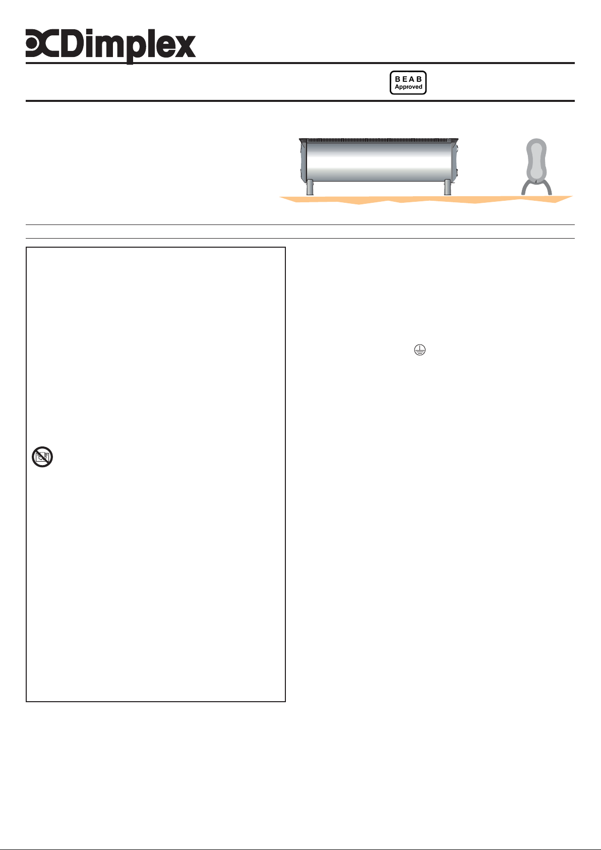
Dimplex Skirting Heaters
Models : DXLAT75, DXLAT150 & DXLAT150Ti
Dimensions
(millimetres)
Models Specification A B
DXLAT75 0.75kW Switch / Thermostat / Neon 250 120
DXLAT150 1.5kW Switch / Thermostat / Neon 305 165
DXLAT150Ti 1.5kW 24Hour Timer / Thermostat 305 165
IMPORTANT : THESE INSTRUCTIONS SHOULD BE READ CAREFULL Y AND RETAINED FOR FUTURE REFERENCE
Important Safety Advice
If the appliance is damaged, check immediately with the
supplier before installation and operation.
WARNING – THIS APPLIANCE MUST NOT BE USED IN A
BATHROOM.
WARNING - DO NOT USE THIS HEA TER IN THE IMMEDIA TE
SURROUNDINGS OF A BA TH, A SHOWER OR A SWIMMING
POOL.
WARNING – THIS HEATER MUST NOT BE LOCATED
IMMEDIATEL Y BELOW A FIXED SOCKET OUTLET .
DO NOT USE THE HEATER UNTIL THE FEET ARE FITTED
CORRECTL Y.
FOLLOW these instructions carefully .
NEVER cover or obstruct in any way the heat outlet slots at
the top of the heater or the air inlet slots in the base of the
heater.
The heater carries the Warning symbol, indicating that
it must not be covered.
Warning: In order to avoid overheating, do not cover the
heater
Caution: In order to avoid a hazard due to inadvertent
resetting of the thermal cutout, this appliance must not be
supplied through an external switching device, such as a
timer, or connected to a circuit that is regularly switched on
and off by the utility.
This appliance is not intended for use by children or other
persons without assistance or supervision if their physical,
sensory or mental capabilities prevent them from using it
safely . Children should be supervised to ensure that they do
not play with the appliance.
If young children, the aged or infirm are likely to be left in the
vicinity of the heater, we advise that adequate precautions
should be taken. We recommend that a guard be fitted to
ensure contact with the heater is avoided and objects cannot
be inserted into the product.
If the mains lead is damaged, it must be replaced by the
manufacturer or its service agent or a similarly qualified
person in order to avoid a hazard.
IMPORTANT : If the plug is not suitable for your socket, the 13
amp plug should be removed. Before wiring the appropriate plug,
please note that the wires in this mains lead are coloured in
accordance with the following code :
GREEN AND YELLOW: EARTH
BLUE : NEUTRAL
BROWN : LIVE
Connect the GREEN AND YELLOW wire to the terminal marked
‘E’ or by the earth symbol
YELLOW.
Connect the BROWN wire to the terminal marked ‘L’ or coloured
RED.
Connect the BLUE wire to the terminal marked ‘N’ or coloured
BLACK.
Positioning the heater
Always ensure that the heater is stood on a firm, level base near
to, but not directly beneath, a suitable mains supply socket,
ensuring at least 300mm clearance from any shelf above.
Ensure that curtains and furniture are not positioned close to the
chosen position, as this would create a potential fire hazard.
See also ‘Important Safety Advice’.
Fitting Feet
NEVER USE THE HEATER FREE ST ANDING WITHOUT THE FEET
FITTED.
, or coloured GREEN or GREEN AND
INDCLTS7RG Issue 1
Fig. 1
Electrical connection
WARNING – THIS APPLIANCE MUST BE EARTHED
This heater must be used on an ~ supply only and the voltage
marked on the heater must correspond to the supply voltage.
This heater is fitted with a rewireable plug incorporating a 13
amp fuse. In the event of replacing the fuse in the plug supplied,
a 13 amp fuse approved by ASTA to BS 1362 must be used. If any
other type of plug is used, a 15 amp fuse must be fitted in the
plug, the adaptor, or at the distribution board.
Fig. 2
Lay the heater on its back, and locate the foot fixing screw (see ‘a’
in Fig. 2). Remove the screw using an X–head screwdriver, then
align foot over slots and holes in base and slide home. Finally
take the foot fixing screw, insert and tighten using a screwdriver
to secure the foot.
Page 2
Using the heater
Plug in and switch on at the wall socket.
On standard models with a neon, the red POWER ON neon will
light when the heater is connected to the power supply.
On timer models the timer clock will operate all the time that the
heater is connected to the mains supply.
On model DXLAT150 the heat selector switch positions are as
follows:
O - Off
I - Low Heat (750W)
II - High Heat (1500W)
On model DXLAT75 there is an On /Off switch – operation as
follows:
O - Off
I - On (750W)
Model DXLAT150Ti is controlled by a Digital Timer – see ‘Digital
Timer Operation’
The heat output is controlled by the thermostat - see ‘Thermostat’
Please note – the element has been coated with a protective film
which will burn off during the first few minutes of use and may
cause a small amount of fuming. This is quite normal – the fumes
are non-toxic and will quickly disappear. We recommend that you
open a window to ventilate the room when using the heater for
the first time.
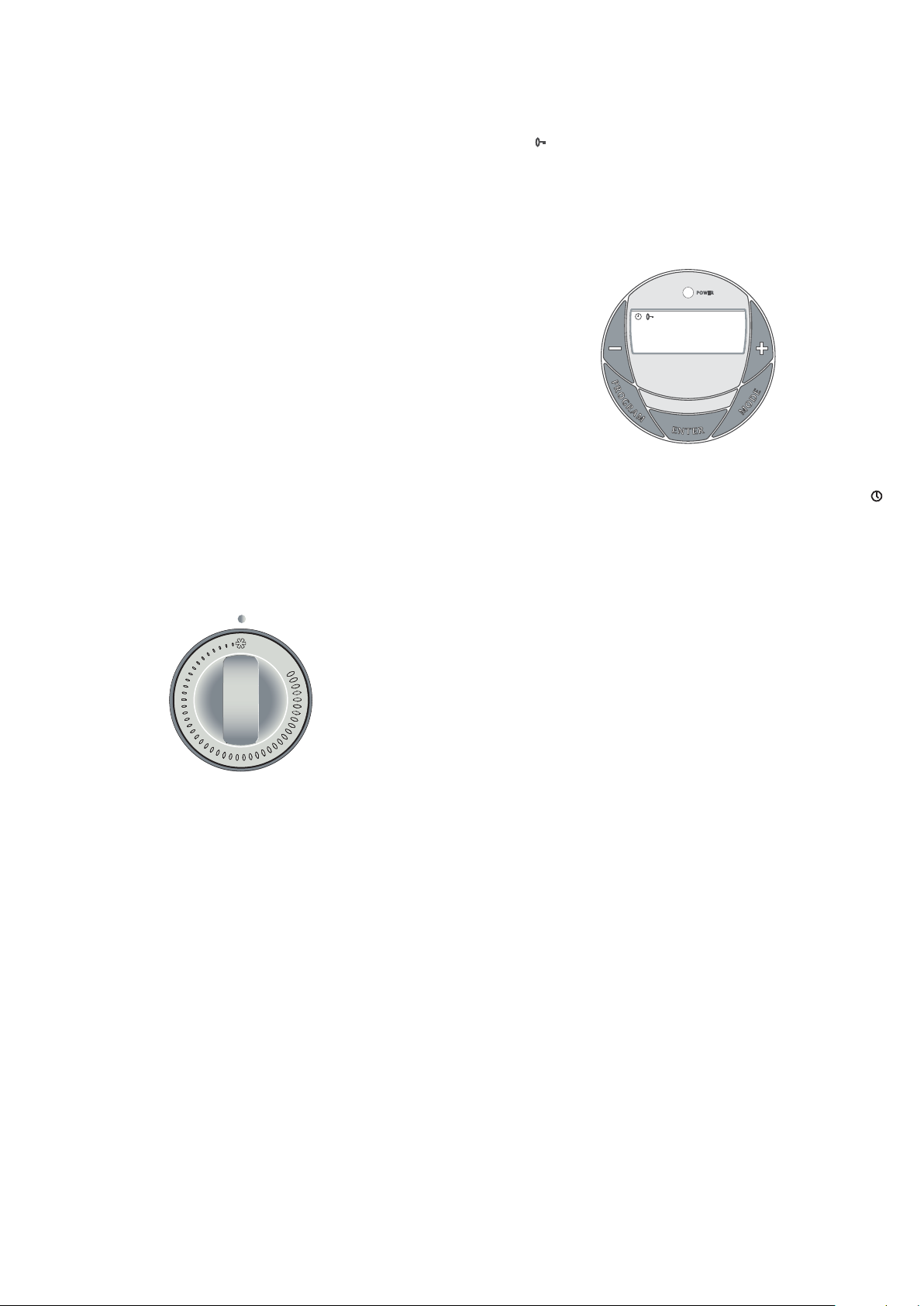
Controls
Thermostat - see Fig. 3
The thermostat controls the heat output according to the room
temperature.
Fig. 3
This ensures that the heater will not produce heat unnecessarily
when the room is warm.
To set the temperature you require, turn the thermostat knob
clockwise until the desired temperature is reached. Alternatively
to heat a cold room quickly, turn the thermostat knob up fully.
When the room has reached the desired temperature, turn the
thermostat knob anti-clockwise until the thermostat just clicks
off.
The heater will now automatically operate at this temperature.
The thermostat also has a frost protection setting marked ‘*’.
This setting is useful in areas such as garages to prevent frost
damage. If the thermostat is set to its minimum setting ‘*’, the
heater will cycle ON and OFF to maintain a temperature of
approximately 5°C to help protect against frosty conditions.
Digital Timer Operation - see Fig. 4
IMPORTANT: Remember to observe all safety warnings when
operating the heater on auto setting, either attended or
unattended.
The timer allows you to select ‘AUTO’ or ‘MAN ON’ by pressing
the ‘MODE’ button until the required MODE appears at the bottom
of the timer display.
‘AUTO’ MODE allows the heater to switch ON and OFF according
to a set 24 Hour program period (see ‘Setting Programs’ section
below).
‘MAN ON’ MODE allows power to the heater uninterrupted by the
program settings.
Key Lock:
If ‘ENTER’ and ‘MODE’ are pressed within 1 second, the keys will
be locked. The user will know the keys are locked as the lock
symbol ‘
’ will be displayed on the top left hand corner of the
screen. To unlock the keypad, press ‘ENTER’ and then ‘MODE’
within 1 second.
Initial Operation
For initial use, plug the heater into a regular household power
point and turn the power on. The timer is now ready to be set up
for use.
ON
13 : 17
P1
OFF
ADVANCE
AUTO MAN ON
Fig. 4
Setting Current Time
1. Press the ‘PROGRAM’ button ONCE. The clock symbol
appears on the top left hand side of the screen. The user can
now set the clock.
2. The hour digit will flash. To adjust the hour use the ‘-‘ & ‘+’
buttons. Confirm the hour digit by pressing ‘ENTER’.
3. Once ‘ENTER’ has been pressed the minutes will flash. To
adjust the minutes use the ‘-‘&‘+’ buttons. Confirm the minute
digit by pressing ‘ENTER’.
4. The timer now returns to the default display.
5. To reset incorrect time, repeat previous steps.
Once the correct time is set, a total of four ON/OFF time programs
can be set for operation. There are two program options.
Setting Programmes
Press the ‘PROGRAM’ key twice to set the programs.
You are now setting the programs starting with P1 ‘ON’.
SETTING P1 ON TIME:
1. To set the hour use the ‘-‘ & ‘+’ buttons. Confirm the hour digit
by pressing ‘ENTER’.
2. To set the minutes use the ‘-‘ & ‘+’ buttons. Confirm the minute
digit by pressing ‘ENTER’.
Note: The minutes can only be set in 10 minute blocks in
programme ‘MODE’.
SETTING P1 OFF TIME:
3. To set the hour use the ‘-‘ & ‘+’ buttons. Confirm the hour digit
by pressing ‘ENTER’.
4. To set the minutes use the ‘-‘ & ‘+’ buttons. Confirm the minute
digit by pressing ‘ENTER’.
Repeat steps 1 to 4 to programme P2, P3 & P4. Af ter programming
P4 ‘OFF’ you automatically exit to the default display.
At any time while programming the timer you can press the
‘PROGRAM’ button to exit to the default display.
The Advance Function
When in ‘AUTO’ MODE, if the ‘+’ button is pressed for longer than
2 seconds the programme will ADVANCE to the next setting
programmed and will only revert back to the program when the
subsequent programme time is reached. When the ‘ADVANCE’
function is running the ‘ADVANCE’ segment will be displayed on
the LCD screen. If the ‘-‘ button is pressed when the ‘ADVANCE’
programme is running the ‘ADVANCE’ feature will be automatically
cancelled and the programme will run as normal.
Page 3

Note - Timer Memory Back Up Batteries - Once the heater has
been left plugged in with the socket switched on for at least 72
hours the timer’s memory back up batteries will be fully charged.
Once the timer batteries are fully charged, if there is a power cut
or if the heater is disconnected from the mains for less than six
months, then the timer will continue to keep time & the settings in
the memory will remain intact.
Safety – overheat protection
For your safety, this appliance is fitted with a thermal cut-out. In
the event that the product overheats for some reason, the cut-out
prevents excessive temperatures on the product by cutting the
power to the heater. Once the heater has cooled down, it will
reset automatically, it will continue to cycle on and of f automatically
until the reason for overheating has been removed.
Important Notes
Although this heater is manufactured to comply with the relevant
safety standards, certain types of carpets could become
discoloured by the temperatures under a portable heater. If you
are concerned about this, we recommend that you contact the
carpet manufacturer for guidance. Alternatively, either stand the
heater on a suitable base to shield the carpet – call our Helpline
for further advice.
You may notice some parts of the element appearing to be hotter
from time to time because of the variable airflow through the
heater. This does not cause a safety hazard.
The heat outlet grille may become discoloured with use – this is
caused by airborne pollution and is not a fault.
Page 4

Cleaning and User Maintenance
WARNING – ALW A YS DISCONNECT FROM THE POWER SUPPL Y
BEFORE CLEANING THE HEATER.
Do not use detergents, abrasive cleaning powder or polish of
any kind on the body of the heater.
Allow the heater to cool, then wipe with a dry cloth to remove dust
and a damp cloth (not wet) to clean off stains. Be careful not to
allow moisture into the heater.
Recycling
For electrical products sold within the European Community.
At the end of the electrical products useful life it
should not be disposed of with household waste.
Please recycle where facilities exist.
Check with your Local Authority or retailer for
recycling advice in your country.
After Sales Service
Your product is guaranteed for three years from the date of
purchase.
Within this period, we undertake to repair or exchange this
product free of charge provided it has been installed and
operated in accordance with these instructions.
Your rights under this guarantee are additional to your statutory
rights, which in turn are not affected by this guarantee.
Should you require after sales service you should contact our
customer services help desk on 0845 600 5111. It would assist
us if you can quote the model number, series, date of purchase,
and nature of the fault at the time of your call.
Please do not return a faulty product to us in the first instance as
this may result in loss or damage and delay in providing you with
a satisfactory service.
Please retain your receipt as proof of purchase.
Glen Dimplex UK Limited
Millbrook House
Grange Drive
Hedge End
Southampton
Hampshire. SO30 2DF
[c] Glen Dimplex UK Limited
All rights reserved. Material contained in this publication may not be reproduced in whole or in part, without prior permission in writing of Glen Dimplex UK Limited.
The product complies with the European Safety Standards EN60335-2-30 and the European Standard Electromagnetic Compatibility (EMC)
EN55014, EN60555-2 and EN60555-3 which cover the essential requirements of EEC Directives 73/23 and 89/336
UK customer help line 8.00am–5.00pm Mon-Fri and 8:30am-1.00pm Sat (Autumn–Winter only)
Customer Services: Tel. 0845 600 5111
Fax. 01489 773053
e-mail customer.services@glendimplex.com
Republic of Ireland Tel. 01 8424833
 Loading...