

Service Manual
Model Number:
DWOP20R
UL Part Number
6909030100
IMPORTANT SAFETY INFORMATION: Always read this manual rst before attempting to service this replace. For your
safety, always comply with all warnings and safety instructions contained in this manual to prevent personal injury or property damage.
Dimplex North America Limited
1367 Industrial Road Cambridge ON Canada N1R 7G8
1-888-346-7539 www.dimplex.com
In keeping with our policy of continuous product development, we reserve the right to make changes without notice.
© 2013 Dimplex North America Limited
REV PCN DATE
00 - 1-NOV-13
7400760100R00

TABLE OF CONTENTS
OPERATION .........................................................3
MAINTENANCE ......................................................4
EXPLODED PARTS DIAGRAM ..........................................5
REPLACEMENT PARTS ...............................................5
WIRING DIAGRAM ...................................................6
HEATER ASSEMBLY REPLACEMENT ....................................7
COMPONENT ACCESS ................................................7
ON/OFF SWITCH REPLACEMENT .......................................7
3 POSITION SWITCH REPLACEMENT ....................................8
THERMOSTAT REPLACEMENT .........................................8
POTENTIOMETER REPLACEMENT ......................................8
REMOTE RECEIVER REPLACEMENT ....................................8
POWER BOARD REPLACEMENT .......................................9
TRANSFORMER REPLACEMENT .......................................9
IR SENSOR REPLACEMENT ...........................................9
POWER CORD REPLACEMENT .........................................9
FAN ASSEMBLY REPLACEMENT - MOTOR AND HOUSING .................10
LIGHT ASSEMBLY REPLACEMENT .....................................10
TROUBLESHOOTING GUIDE ..........................................11
Always use a qualied technician or service agency to repair this replace.
!
NOTE: Procedures and techniques that are considered important enough to emphasize.
CAUTION: Procedures and techniques which, if not carefully followed, will result in damage to the equipment.
WARNING: Procedures and techniques which, if not carefully followed, will expose the user to the risk of re, serious
injury, or death.
2 www.dimplex.com
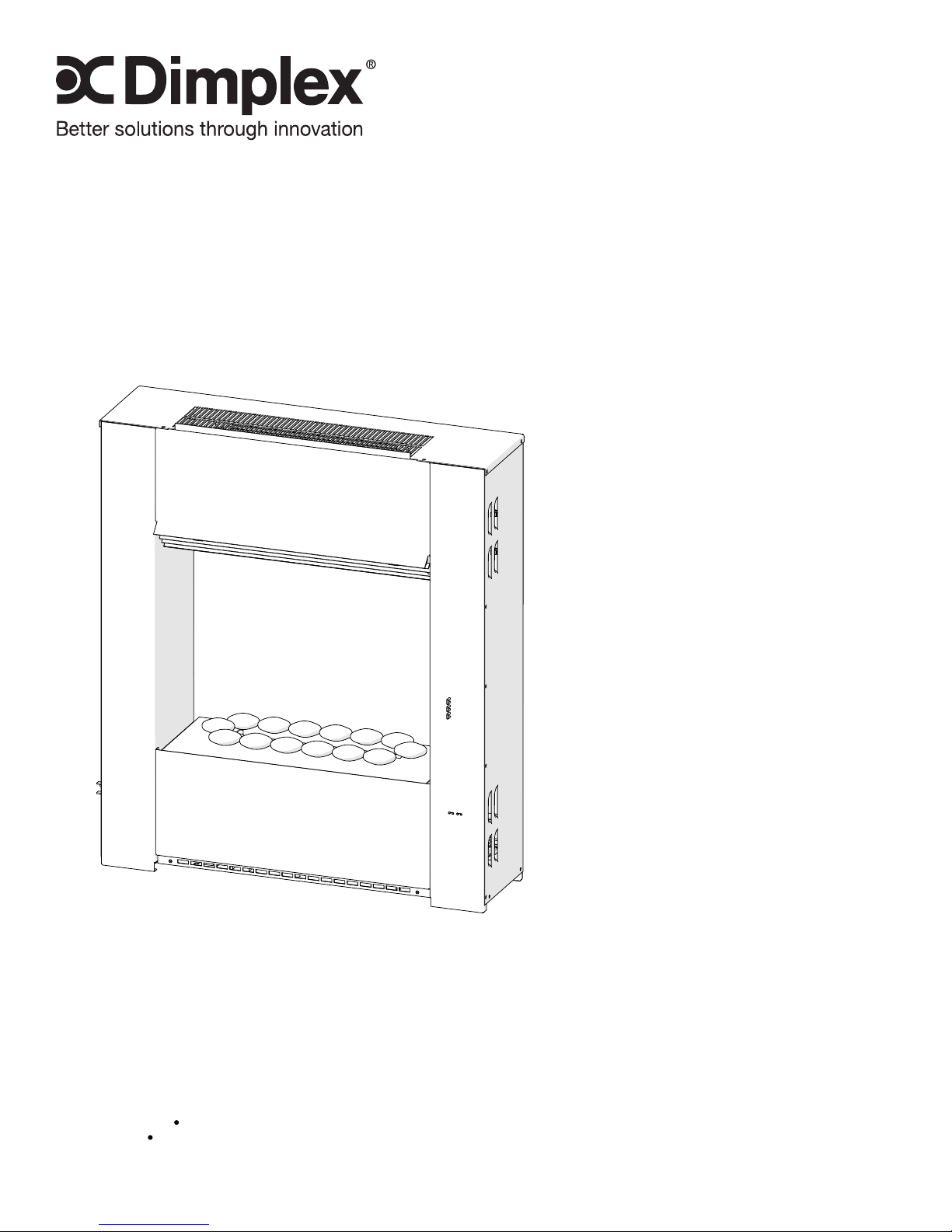
OPERATION
Figure 1
2kw
B
!
where background noise is very low, it may be possible to
hear a sound which is related to the operation of the ame
effect. This is normal and should not be a cause for concern.
!
wall in a level position.
The manual controls for the wall mount engine are located
on the bottom of the unit. (Figure 1)
A. On/Off Switch
Supplies power to the engine.
B. Thermostat Control
To adjust the temperature to your individual requirements,
turn the thermostat control backwards all the way to turn on
the heater. When the room reaches the desired temperature, turn the thermostat knob forward until you hear a click.
Leave thermostat in this position to maintain the room tem-
perature at this setting. For additional heat, turn clockwise
until you hear the click again and the heater will turn on.
C. Mode Selector Switch
Press once to turn on the ame effect. This will be indicated
by an audible “beep”. Although the lights turn on immedi-
ately it will take 30 seconds before the ame effect starts.
• Press again to give ame effect and full heat. This will
• Press again to return to ame effect only. This will be
• Press to put re in to standby mode. This will be
D. Flame Intensity Control
Adjusts the intensity of the ame and smoke effect when the
heater has been activated.
Turning the control knob towards you decreases the inten-
sity of the ame and smoke effect. Turning the control knob
away from you will increase the ame and smoke effect.
!
changes you may make on the ame control knob.
!
off after 30 seconds. See instructions under Maintenance
Section for relling tank. When this procedure is complete,
the main lamps will illuminate but it will take 30 seconds
before the ames return.
A
C
D
NOTE: When the engine is used in an environment
NOTE: Always ensure that the appliance is xed to the
be indicated by two “beeps”.
indicated by one “beep”.
indicated by one “beep”.
NOTE: Give the ame generator some time to react to
NOTE: When the water tank is empty the unit will turn
Resetting the Temperature Cutoff Switch
Should the heater overheat, an automatic cut out will turn
the replace off and it will not come back on without being
reset. It can be reset by switching the On/ Off Switch to Off
and waiting ten (10) minutes before switching the unit back
on.
CAUTION: If you need to continuously reset the heater,
unplug the unit and call Dimplex North America Limited at
1-888-346-7539 for technical support. Please have your
model and serial number ready when calling.
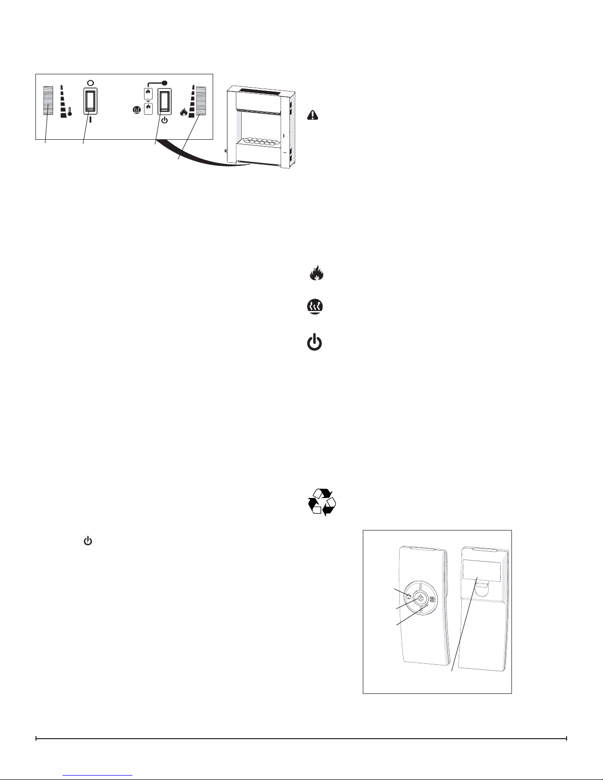
Remote Control
The On/Off Switch must be in the ‘ON’ ( I ) position in order
for the remote control to operate. There are 3 buttons on
the remote control. (Figure 2)
!
NOTE: To operate correctly the remote control must be
pointed towards the heater outlet.
The remote control functions are as follows:
Press once to turn on Flame effect only. This will be
indicated by one beep.
Press once to turn on Full heat and Flame effect. This
will be indicated by two beeps.
Standby - This will be indicated by one beep.
!
NOTE: Once the mist has been activated, the unit will
have to be turned Off, using either the momentary button,
on the unit, or the Off button on the remote control, then
back on to return to Level 1 - Logs and Light only operation.
Battery Replacement
To replace the battery:
1. Slide battery cover open on the remote control (Figure
10).
2. Install two 1.5 Volt (AAA) battery in the battery holder.
3. Close the battery cover.
Battery must be recycled or disposed of properly.
Check with your Local Authority or Retailer for recycling advice in your area.
Figure 2
Flame
Button
Standby
Button
Heat
Button
Battery Cover
3
MAINTENANCE
WARNING: Disconnect power before attempting any
maintenance or cleaning to reduce the risk of re, electric shock or damage to persons.
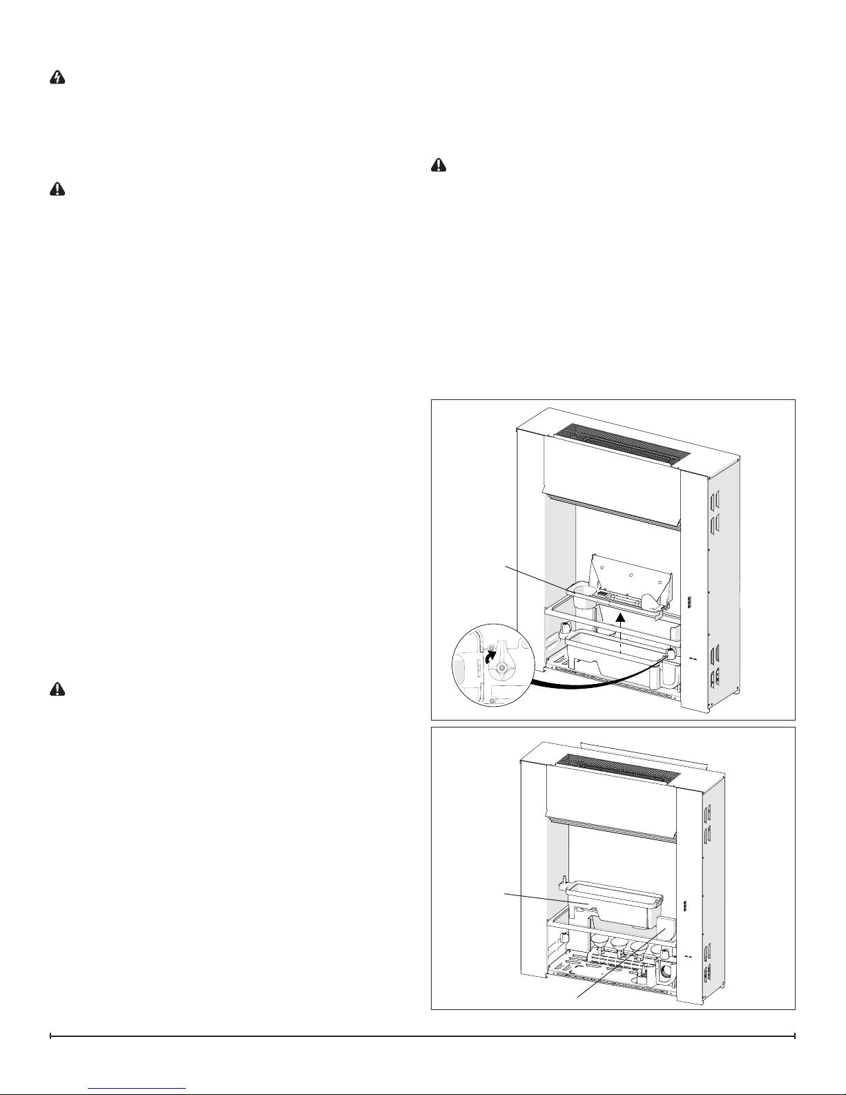
Filling the water tank
When the water tank is empty, the ame effect shuts off
and you will hear 2 audible beeps, follow these steps.
CAUTION: Allow at least ve minutes for components to
cool before disassembling the unit to rell.
1. Turn the On/Off switch to the off position (0) (Figure 1)
2. Gently remove the rock media and the media tray and
place them carefully on the ground.
3. Remove the rell container by lifting upwards and
outwards.
4. Rell the container with tap water.
!
NOTE: Normal tap water can be used in the Optimyst®
as long as the tap water is not considered to be hard water.
In the event your tap water is hard, you may use softened
water or distilled water with 1/8 tsp of salt (0.5 mL) added to
the water reservoir. (The addition of additional salt should
only be when you notice that the unit is not producing mist
as expected.)
5. Screw the cap back on, do not overtighten.
6. Return the rell container to the sump, with the tank
cap facing down and the at side of the tank facing
outward.
7. Gently place the media tray and rock media back into
position.
8. Turn the On/Off switch to the off position (I). (Figure 1)
If you do not intend on using the unit for longer than 2
weeks, empty and drain the unit of water, and dry all of the
water containing components.
media.
Cleaning
It is recommended that all of the components that contain
water are cleaned with soap and water on a biweekly basis. A small brush has been included to assist in cleaning
difcult items/areas, i.e. the transducer.
CAUTION: Do not put plastic components in the dish-
washer.
Filter Cleaning
The air lter can be removed and gently rinsed with water
to clean and dried on a towel before reinstalling.
!
NOTE: Replace the lter so that the course black lter is
facing the front of the engine.
Surface Cleaning
Use a warm damp cloth only to clean surfaces of the engine. Do not use abrasive cleaners.
!
NOTE: If you need to move the unit ensure that all of
the components that contain water have been emptied before relocating.
Figure 3
Top
Cover
Replacing the Light bulbs
If a large amount of the smoke appears grey or colourless it
may be that one or more of the light bulbs have burnt out.
CAUTION: Allow at least twenty minutes for light bulbs
to cool before touching bulbs to avoid accidental burning of
skin.
1. Leaving the ame effect on, remove the rock media,
tray and water tank and lift out the top cover (Figure 3).
2. View the lamps from a distance in front of the re and
observe which lamp needs to be changed.
3. Turn the unit off, and unplug the engine.
4. Leave the appliance for 20 minutes to allow the lamps
to cool down before removing them.
5. Remove the water tank and sump (Figure 4) by lifting
upwards and placing to the side.
6. Remove the defective bulb, by gently lifting vertically
and disengaging the pins from the lamp holder.
!
NOTE: Replacement light bulbs can be obtained by
contacting Dimplex Customer Service at 1-888-346-7539.
7. Carefully insert the two pins of the new bulb into the
two holes in the lamp holder. Push lamp rmly in place.
8. Replace the top cover, rell container, media tray and
Figure 4
Sump
Filter
4 www.dimplex.com
 Loading...