

Page 1
Service Manual
Model
DWF3651
DWF5252B
Part Number
6908492100
6909770159
IMPORTANT SAFETY INFORMATION: Always read this manual rst before attempting to
service this replace. For your safety, always comply with all warnings and safety instructions
contained in this manual to prevent personal injury or property damage.
Dimplex North America Limited
1367 Industrial Road Cambridge ON Canada N3H 4W3
1-888-346-7539 www.dimplex.com
In keeping with our policy of continuous product development, we reserve the right to make changes without notice.
© 2016 Dimplex North America Limited
REV PCN DATE
00 - 13-JAN-16
01 - 3-MAY-16
7400930000R01
Page 2

TABLE OF CONTENTS
Operation ...........................................................3
Maintenance .........................................................4
Exploded Parts Diagram ...............................................5
Replacement Parts List ................................................5
Wiring Diagram ......................................................6
Partially Reective Glass Replacement ..................................7
Switchboard Replacement .............................................7
Display/Control Board Replacement .....................................8
Power Cord Replacement ..............................................8
Relay Board Replacement .............................................9
AC/DC Adapter Replacement ...........................................9
Heater Assembly Replacement ........................................10
Flicker Rod Replacement .............................................10
Flicker Motor Replacement. . . . . . . . . . . . . . . . . . . . . . . . . . . . . . . . . . . . . . . . . . . . 11
LED Light Strip Replacement ..........................................12
Troubleshooting Guide ...............................................13
Always use a qualied technician or service agency to repair this replace.
!
NOTE: Procedures and techniques that are considered important enough to emphasize.
CAUTION: Procedures and techniques which, if not carefully followed, will result in damage to the equipment.
WARNING: Procedures and techniques which, if not carefully followed, will expose the user to the risk of re, serious
injury, or death.
2 www.dimplex.com
Page 3
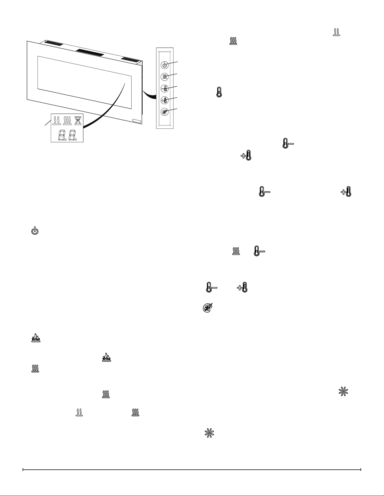
OPERATION
Figure 1
Floating
Display
TM
!
NOTE: The unit can be operated in Heat Only Mode.
When the unit is only running with the heater, the (low
heat) or the (high heat) icon and the intake temperature
will continuously be displayed on the On Screen Display.
!
A
C
D
E
F
NOTE: The heater may emit a slight, harmless odor
when rst used. This odor is a normal condition caused
by initial heating of internal heater parts and will not occur
again.
D & E. Thermostat Controls
Adjusts the temperature set point to your individual requirements. Once the desired set temperature is reached the
heater will turn off. The heater will cycle on and off to maintain the desired set temperature. The default temperature
setting is 72°F (22°C).
The unit can be controlled by either the manual controls
which are located on the right side of the replace or the
remote (Figure 1 & 2).
The replace is supplied with an IR multifunction remote
control.
!
NOTE: To operate correctly, the remote control must be
pointed towards the Floating DisplayTM.
!
NOTE: Before attempting any operation with the remote,
pull the plastic insulator strip out from between the remote
casing and battery cover.
A. Standby
Turns the unit On and Off.
→ Activated by pressing the Standby button on the remote
or the unit.
• The unit will turn on with the same functions that it was
set to when it was turned Off and the intake temperature
will be indicated on the On Screen Display.
!
NOTE: If the unit is turned off when the ame effect
is Off, when the unit is turned back on the ame will be
restored.
!
NOTE: When any button is pressed the intake temperature will be displayed on the On Screen Display for 5
seconds.
B. Flame Effects
Turns the ame effect On and Off.
→ Activated by pressing the button on the remote.
C. Heat ON/OFF
Cycles the unit sequentially through the 3 settings: Low
Heat, High Heat and Off.
→ Activated by pressing the button on the unit or the
remote.
• Indicated by the (low heat) or the (high heat) icon
and the intake temperature being displayed on the On
Screen Display, for 5 seconds before turning off.
!
NOTE: After the heater is switched off, there is a 60
second fan delay, where the fan will continue running before turning off.
→ Adjusted by pressing the
point and the to increase the set point on the remote.
• The On Screen Display will indicate the temperature set
point as it is adjusted.
!
NOTE: Holding the button down, then press on
the unit, will change the temperature from °C to °F, or vice
versa.
to decrease the set
Disable Heat
If desired, depending on the season, the heater on the unit
can be disabled. The unit will operate in the same fashion,
with remainder of the controls.
Pressing the and buttons on the unit at the same
time and holding for 2 seconds will disable and enable the
heater.
!
NOTE: When the heater has been disabled and either
the or the is pressed the On Screen Display will
indicate “--”.
F. Color Themes
Different presets of ambient lighting color combinations
contained in the unit.
→ Changed by repeatedly pressing the corresponding but-
ton on the remote or the unit.
• Cycles through the different preset ambient lighting settings of the unit, this includes different combinations of
colors of the top lighting, ame base and media lighting
(if applicable).
!
NOTE: The last theme of the cycle is a prism where the
unit cycles through a variety of colors. Pressing the
button stops the cycling and holds the unit on the preferred
color, indicated by a solid circle. When the unit is on prism,
and is cycling through the colors, a rotating circle will be
displayed.
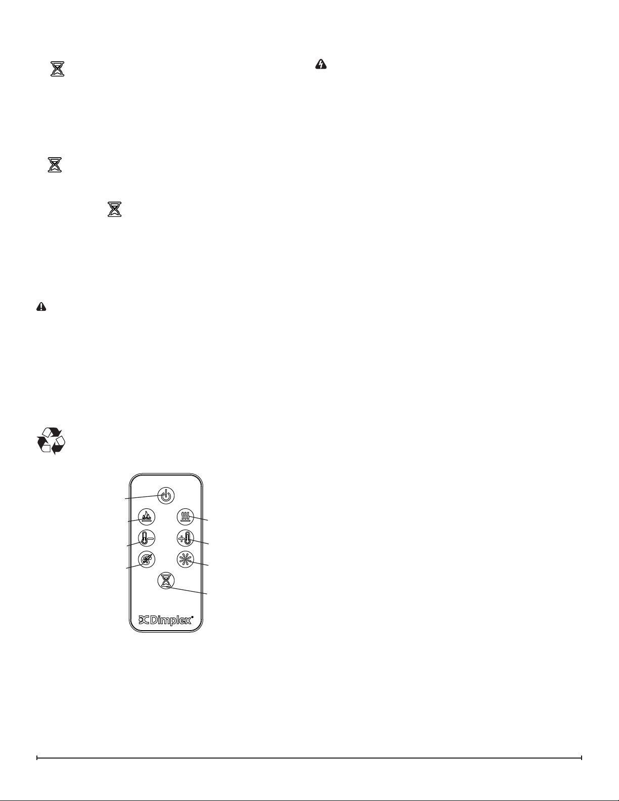
G.
Changes the brightness of the lights in the unit.
→ Adjusted by repeatedly pressing the corresponding but-
Brightness
ton on the remote.
3
Page 4
• Indicated by the second digit on the Floating Display™
changing to show: “H” (high), and “L” (low).
H. Sleep Timer
The Sleep Timer can be set to automatically shut off the
replace after a preset time (from 30 minutes to 8 hours).
→ To set the timer press the timer button on the remote,
repeatedly, until the desired time is displayed.
• The On Screen Display will display the different times as
it is adjusted. Once the timer has begun, pressing the
button will display the time remaining before the unit
turns Off.
!
NOTE: The Sleep Timer can be cancelled at any time
by pressing the button repeatedly until the sleep timer
displays nothing.
Resetting the Temperature Cutoff Switch
Should the heater overheat, an automatic cut out will turn
the heater off and it will not come back on without being
reset. It can be reset by unplugging the unit and waiting 5
minutes before plugging the unit back in.
CAUTION: If you need to continuously reset the heater,
unplug the unit and call technical support at 1-888-346-
7539.
Remote Control Battery Replacement
To replace the battery:
1. Slide battery cover open on the remote control. Cor-
rectly install one 3 Volt (CR2032 [longer life] or CR2025)
battery in the battery holder.
2. Close the battery cover.
Battery must be recycled or disposed of properly.
Check with your Local Authority or Retailer for recycling advice in your area
MAINTENANCE
WARNING: Disconnect power before attempting any
maintenance or cleaning to reduce the risk of re,
electric shock or damage to persons.
Partially Reective Glass Cleaning
The Partially Reective Glass is cleaned in the factory
during the assembly operation. During shipment,
installation, handling, etc., the Partially Reective Glass
may collect dust particles; these can be removed by
dusting lightly with a clean dry cloth.
To remove ngerprints or other marks, the Partially
Reective Glass can be cleaned with a damp cloth. The
Partially Reective Glass should be completely dried with a
lint free cloth to prevent water spots. To prevent scratching,
do not use abrasive cleaners.
Fireplace Surface Cleaning
Use only a damp cloth to clean painted surfaces of the
replace. Do not use abrasive cleaners.
Servicing
Except for installation and cleaning described in this
manual, an authorized service representative should
perform any other servicing.
Figure 2
A
B
D
F
C
E
G
H
4 www.dimplex.com
Page 5
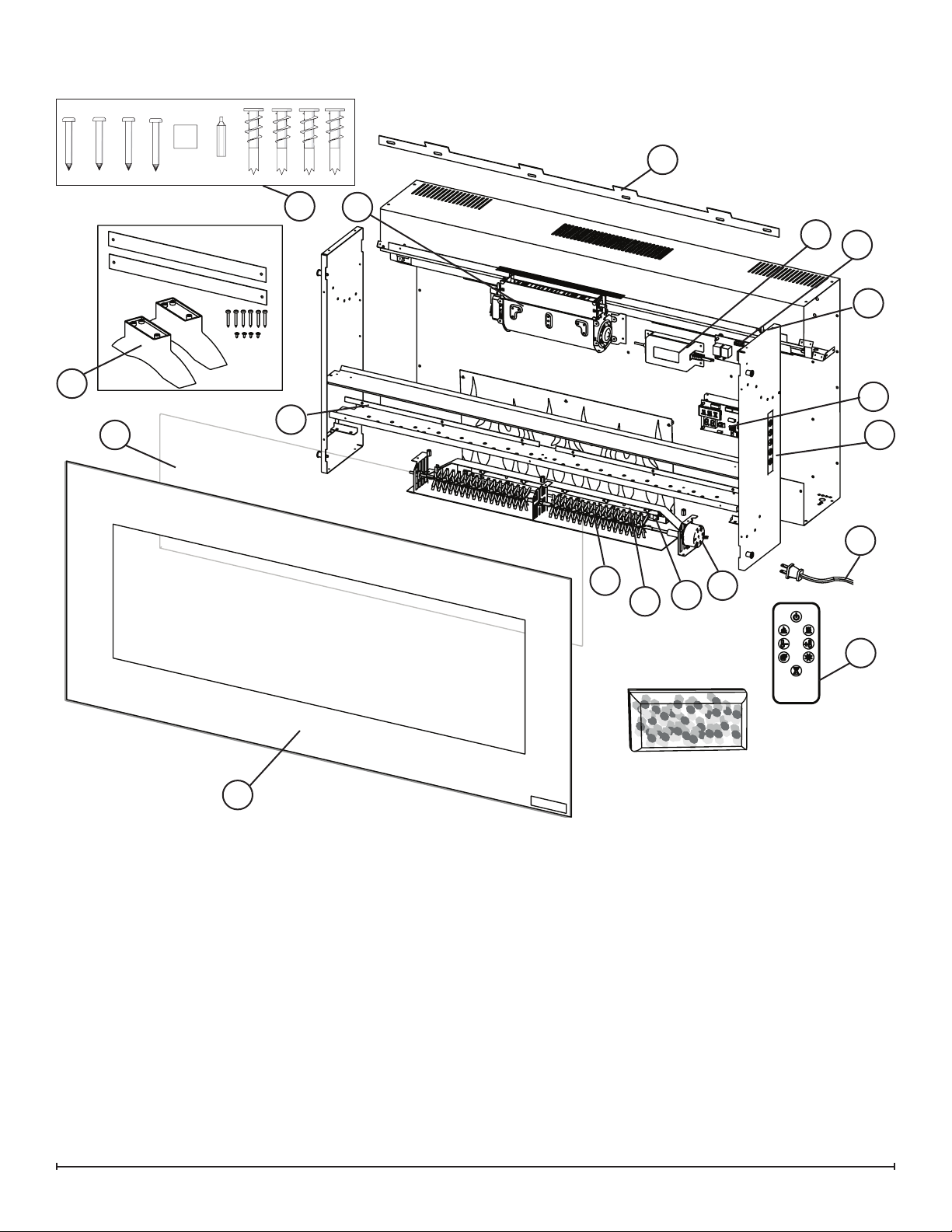
EXPLODED PARTS DIAGRAM
8
15
7
1
12
11
14
9
17
3
10
4
6
18
19
5
13
2
REPLACEMENT PARTS LIST
1. Heater Assembly (with Cutout) ............2203610400RP
2. Front Glass - DWF3651 . . . . . . . . . . . . . . . . 5902440100RP
DWF5252. . . . . . . . . . . . . . . . . 5902410400RP
3. Partially Reective Glass ................5902420100RP
4. Power Cord ..........................4100010900RP
5. Flicker Motor. . . . . . . . . . . . . . . . . . . . . . . . . . 2000500100RP
6. Flicker Rod ..........................5901070200RP
7. Mounting Hardware Kit. . . . . . . . . . . . . . . . . . 9600350100RP
8. Mounting Bracket . . . . . . . . . . . . . . . . . . . . . . 1017130259RP
9. Display/ Control Board . . . . . . . . . . . . . . . . . . 3001430200RP
10. Switchboard ..........................3001520100RP
11. Relay Board . . . . . . . . . . . . . . . . . . . . . . . . . . 3001440200RP
12. AC/DC Adapter ........................2100250100RP
13. Remote Control .......................6700520200RP
14. Thermistor ...........................3001560100RP
15. Surface Mount Kit (DWF3651 only) ........9601410100RP
16. Acrylic Media .........................1400150100RP
17. Media LED Set (RGB) ..................9601180100RP
18. Flame LED Light Assembly (Amber) .......3001420200RP
19. Flame LED Light Assembly (RGB). . . . . . . . . 3001570200RP
5
Page 6

WIRING DIAGRAM
CN4
CN6
CN3
CN6
CN4
CN3
6 www.dimplex.com
Page 7

PARTIALLY REFLECTIVE GLASS REPLACEMENT
Tools Required: Phillips head screwdriver
WARNING: If the replace was operating prior to ser-
vicing, allow at least 10 minutes for light bulbs and heating
elements to cool off to avoid accidental burning of skin.
WARNING: Disconnect power before attempting any
maintenance to reduce the risk of electric shock or damage
to persons.
1. On either side of the rebox, remove the retaining
screws and carefully remove the glass assembly from
the rest of the assembly. (Figure 3)
2. Carefully remove the acrylic media from the front tray.
3. If applicable, remove the replace assembly from the
wall by carefully lifting it upward, releasing it from the
anges of the wall-mounting bracket. (Figure 4).
4. Carefully set the unit upright on a at working surface.
!
NOTE: If necessary, lay a protective barrier between
the unit and your work surface, (i.e. cloth, cardboard, thick
plastic) to avoid scratching your work surface.
5. On the right end, with the switchboard, remove the ten
screws around the outside of the end panel. (Figure 5)
6. Lay unit on its back and remove the remaining 9 screws
from the end panel.
Figure 3
Glass Retaining
Screw
Figure 4
Wall Bracket
Figure 5
To Remove
7. Remove the end panel being
careful not to add any strain
to the wires connecting to the
switchboard.
8. Gently guide the partially reective glass out the open side of
the rebox and replace with new
piece.
9. Re-assemble the remainder of
the replace in reverse order from
the instructions above.
!
NOTE: Be sure that the anges
on the end panel are positioned on
the interior of the outside panel of
the replace.
SWITCHBOARD REPLACEMENT
Tools Required: Phillips head screwdriver
Small adjustable wrench
WARNING: If the replace was operating prior to ser-
vicing, allow at least 10 minutes for light bulbs and heating
elements to cool off to avoid accidental burning of skin.
WARNING: Disconnect power before attempting any
maintenance to reduce the risk of electric shock or damage
to persons.
1. On either side of the rebox, remove the retaining
screws and carefully remove the glass assembly from
the rest of the assembly. (Figure 3)
2. Carefully remove the acrylic media from the front tray.
3. If applicable, remove the replace assembly from the
wall by carefully lifting it upward, releasing it from the
anges of the wall-mounting bracket. (Figure 4).
4. Carefully set the unit upright on a at working surface.
!
NOTE: If necessary, lay a protective barrier between
the unit and your work surface, (i.e. cloth, cardboard, thick
plastic) to avoid scratching your work surface.
5. On the right end, with the switchboard, remove the ten
screws around the outside of the end panel. (Figure 5)
6. Lay unit on its back and remove the remaining 9 screws
from the end panel.
7. Remove the end panel being careful not to add any
strain to the wires connecting to the switchboard. (Figure 6)
8. Gently guide the partially reective glass out the open
side of the rebox.
9. Follow the switchboard wiring to the display/control
board and replace the old connection with the new connection.
10. Locate and remove the defective switchboard.
11. Install the new switchboard.
12. Re-assemble the remainder of the replace in reverse
order from the instructions above.
7
Page 8

Figure 6
!
NOTE: Be sure that the anges on the end panel are
positioned on the interior of the outside panel of the re-
place.
Heater Assembly
AC/DC Adapter
Relay Board
Display/Control
Board
Switch
Board
Power
Cord
DISPLAY/CONTROL BOARD REPLACEMENT
Tools Required: Phillips head screwdriver
WARNING: If the replace was operating prior to ser-
vicing, allow at least 10 minutes for light bulbs and heating
elements to cool off to avoid accidental burning of skin.
WARNING: Disconnect power before attempting any
maintenance to reduce the risk of electric shock or damage
to persons.
1. On either side of the rebox, remove the retaining
screws and carefully remove the glass assembly from
the rest of the assembly. (Figure 3)
2. Carefully remove the acrylic media from the front tray.
3. If applicable, remove the replace assembly from the
wall by carefully lifting it upward, releasing it from the
anges of the wall-mounting bracket. (Figure 4).
4. Carefully set the unit upright on a at working surface.
!
NOTE: If necessary, lay a protective barrier between
the unit and your work surface, (i.e. cloth, cardboard, thick
plastic) to avoid scratching your work surface.
5. On the right end, with the switchboard, remove the ten
screws around the outside of the end panel. (Figure 5)
6. Lay unit on its back and remove the remaining 9 screws
from the end panel.
7. Remove the end panel being careful not to add any
strain to the wires connecting to the switchboard.
8. Gently guide the partially reective glass out the open
side of the rebox.
!
NOTE: The wires are grouped together with tie wraps,
which may need to cut to easily access the different wires.
9. Locate the display/control board and remove the two
screws that secure the assembly to the unit. (Figure 6)
10. Carefully transfer the wire connections from the original
control board onto the new control board.
11. Re-assemble the replace in reverse order from the
instructions above.
!
NOTE: If any tie wraps were removed, replace and en-
sure that none of the wires are pinched during reassembly.
!
NOTE: Be sure that the anges on the end panel are
positioned on the interior of the outside panel of the re-
place.
POWER CORD REPLACEMENT
Tools Required: Phillips head screwdriver
Needle-nose pliers
Flat Head Screwdriver
WARNING: If the replace was operating prior to ser-
vicing, allow at least 10 minutes for light bulbs and heating
elements to cool off to avoid accidental burning of skin.
WARNING: Disconnect power before attempting any
maintenance to reduce the risk of electric shock or damage
to persons.
1. On either side of the rebox, remove the retaining
screws and carefully remove the glass assembly from
the rest of the assembly. (Figure 3)
2. Carefully remove the acrylic media from the front tray.
3. If applicable, remove the replace assembly from the
wall by carefully lifting it upward, releasing it from the
anges of the wall-mounting bracket. (Figure 4).
4. Carefully set the unit upright on a at working surface.
!
NOTE: If necessary, lay a protective barrier between
the unit and your work surface, (i.e. cloth, cardboard, thick
plastic) to avoid scratching your work surface.
5. On the right end, with the switchboard, remove the ten
screws around the outside of the end panel. (Figure 5)
6. Lay unit on its back and remove the remaining 9 screws
from the end panel.
7. Remove the end panel being careful not to add any
strain to the wires connecting to the switchboard.
8. Gently guide the partially reective glass out the open
side of the rebox.
!
NOTE: The wires are grouped together with tie wraps,
which may need to cut to easily access the different wires.
9. Follow the wiring from the power cord (Figure 6) up to
the upper cavity of the unit, removing any tie wraps and
remove the connections, taking note of the original locations.
10. With needle nosed pliers, squeeze and push the grom-
met securing the power cord out of the casing, going
into the upper cavity of the unit.
11. Insert the new power cord and grommet, reattaching the
wire with new tie wraps.
12. Reconnect the wires according to their original congu-
ration.
13. Re-assemble the remainder of the replace in reverse
8 www.dimplex.com
Page 9

order from the instructions above.
!
NOTE: If any tie wraps were removed, replace and en-
sure that none of the wires are pinched during reassembly.
!
NOTE: Be sure that the anges on the end panel are
positioned on the interior of the outside panel of the re-
place.
RELAY BOARD REPLACEMENT
Tools Required: Phillips head screwdriver
Flat Head Screwdriver
WARNING: If the replace was operating prior to ser-
vicing, allow at least 10 minutes for light bulbs and heating
elements to cool off to avoid accidental burning of skin.
Figure 7
Heater Screws
WARNING: Disconnect power before attempting any
maintenance to reduce the risk of electric shock or damage
to persons.
1. On either side of the rebox, remove the retaining
screws and carefully remove the glass assembly from
the rest of the assembly. (Figure 3)
2. Carefully remove the acrylic media from the front tray.
3. If applicable, remove the replace assembly from the
wall by carefully lifting it upward, releasing it from the
anges of the wall-mounting bracket. (Figure 4).
4. Carefully set the unit upright on a at working surface.
!
NOTE: If necessary, lay a protective barrier between
the unit and your work surface, (i.e. cloth, cardboard, thick
plastic) to avoid scratching your work surface.
5. On the right end, with the switchboard, remove the ten
screws around the outside of the end panel. (Figure 5)
6. Lay unit on its back and remove the remaining 9 screws
from the end panel.
7. Remove the end panel being careful not to add any
strain to the wires connecting to the switchboard.
8. Gently guide the partially reective glass out the open
side of the rebox.
!
NOTE: The wires are grouped together with tie wraps,
which may need to cut to easily access the different wires.
9. Locate the display/control board and remove the two
screws that secure the assembly to the unit.
10. Locate the relay board and carefully transfer the wire
connections from the original board onto the new board.
!
NOTE: For easier access the lower front panel can be
removed by removing the 5 screws along the bottom of the
front panel, the 3 screws along the back of the unit (Figure
7) and the 5 screws on the left hand panel.
11. Reconnect the wires according to their original congu-
ration.
12. Re-assemble the remainder of the replace in reverse
order from the instructions above.
!
NOTE: If any tie wraps were removed, replace and en-
sure that none of the wires are pinched during reassembly.
!
NOTE: Be sure that the anges on the end panel are
positioned on the interior of the outside panel of the re-
Front Panel Screws
place.
AC/DC ADAPTER REPLACEMENT
Tools Required: Phillips head screwdriver
Flat Head Screwdriver
1. On either side of the rebox, remove the retaining
screws and carefully remove the glass assembly from
the rest of the assembly. (Figure 3)
2. Carefully remove the acrylic media from the front tray.
3. If applicable, remove the replace assembly from the
wall by carefully lifting it upward, releasing it from the
anges of the wall-mounting bracket. (Figure 4).
4. Carefully set the unit upright on a at working surface.
!
NOTE: If necessary, lay a protective barrier between
the unit and your work surface, (i.e. cloth, cardboard, thick
plastic) to avoid scratching your work surface.
5. On the right end, with the switchboard, remove the ten
screws around the outside of the end panel. (Figure 5)
6. Lay unit on its back and remove the remaining 9 screws
from the end panel.
7. Remove the end panel being careful not to add any
strain to the wires connecting to the switchboard.
8. Gently guide the partially reective glass out the open
side of the rebox.
!
NOTE: The wires are grouped together with tie wraps,
which may need to cut to easily access the different wires.
9. Locate the display/control board and remove the two
screws that secure the assembly to the unit.
10. Locate the relay board and carefully transfer the wire
connections from the original board onto the new board.
!
NOTE: For easier access the lower front panel can be
removed by removing the 5 screws along the bottom of the
front panel, the 3 screws along the back of the unit (Figure
7) and the 5 screws on the left hand panel.
11. Reconnect the wires according to their original congu-
ration.
12. Re-assemble the remainder of the replace in reverse
9
Page 10

order from the instructions above.
!
NOTE: If any tie wraps were removed, replace and en-
sure that none of the wires are pinched during reassembly.
!
NOTE: Be sure that the anges on the end panel are
positioned on the interior of the outside panel of the re-
place.
HEATER ASSEMBLY REPLACEMENT
Tools Required: Phillips head screwdriver
Flat Head Screwdriver
WARNING: If the replace was operating prior to ser-
vicing, allow at least 10 minutes for light bulbs and heating
elements to cool off to avoid accidental burning of skin.
WARNING: Disconnect power before attempting any
maintenance to reduce the risk of electric shock or damage
to persons.
1. On either side of the rebox, remove the retaining
screws and carefully remove the glass assembly from
the rest of the assembly. (Figure 3)
2. Carefully remove the acrylic media from the front tray.
3. If applicable, remove the replace assembly from the
wall by carefully lifting it upward, releasing it from the
anges of the wall-mounting bracket. (Figure 4).
4. Carefully set the unit upright on a at working surface.
!
NOTE: If necessary, lay a protective barrier between
the unit and your work surface, (i.e. cloth, cardboard, thick
plastic) to avoid scratching your work surface.
5. On the right end, with the switchboard, remove the ten
screws around the outside of the end panel. (Figure 5)
6. Lay unit on its back and remove the remaining 9 screws
from the end panel.
7. Remove the end panel being careful not to add any
strain to the wires connecting to the switchboard.
8. Gently guide the partially reective glass out the open
side of the rebox.
!
NOTE: The wires are grouped together with tie wraps,
which may need to cut to easily access the different wires.
9. Remove the lower front panel by removing the 5 screws
along the bottom of the front panel, the 3 screws along
the back of the unit (Figure 7) and the 5 screws on the
left hand panel.
10. Locate the display/control board and remove the two
screws that secure the assembly to the unit, this will
allow the lower front panel to be moved more out of the
way for better access.
11. Locate the heater assembly and remove the 4 screws
securing the assembly to the unit. (Figure 7)
!
NOTE: There are a couple of small washers installed
on the top two screws, these will need to be replaced when
the new heater is installed.
12. Gently pull the heater assembly out of the upper cavity,
and remove all of the wiring connections noting their
original location.
13. Connect the wiring to the new heater assembly and replace the four screws to secure the assembly to the unit.
14. Re-assemble the remainder of the replace in reverse
order from the instructions above.
!
NOTE: If any tie wraps were removed, replace and en-
sure that none of the wires are pinched during reassembly.
!
NOTE: Be sure that the anges on the end panel are
positioned on the interior of the outside panel of the re-
place.
FLICKER ROD REPLACEMENT
Tools Required: Phillips head screwdriver
Needle-nose pliers
WARNING: If the replace was operating prior to ser-
vicing, allow at least 10 minutes for light bulbs and heating
elements to cool off to avoid accidental burning of skin.
WARNING: Disconnect power before attempting any
maintenance to reduce the risk of electric shock or damage
to persons.
1. On either side of the rebox, remove the retaining
screws and carefully remove the glass assembly from
the rest of the assembly. (Figure 3)
2. Carefully remove the acrylic media from the front tray.
3. If applicable, remove the replace assembly from the
wall by carefully lifting it upward, releasing it from the
anges of the wall-mounting bracket. (Figure 4).
4. Carefully set the unit upright on a at working surface.
!
NOTE: If necessary, lay a protective barrier between
the unit and your work surface, (i.e. cloth, cardboard, thick
plastic) to avoid scratching your work surface.
5. On the right end, with the switchboard, remove the ten
screws around the outside of the end panel. (Figure 5)
6. Lay unit on its back and remove the remaining 9 screws
from the end panel.
7. Remove the end panel being careful not to add any
strain to the wires connecting to the switchboard.
8. Gently guide the partially reective glass out the open
side of the rebox.
!
NOTE: The wires are grouped together with tie wraps,
which may need to cut to easily access the different wires.
9. Remove both sets of the 3 end panel screws and the 5
front screws that hold the Media Tray in place. (Figure
8)
10. Inside the lower cavity, locate the Flicker Motor and the
Flicker Rod. The Flicker Rod can be removed by removing the brackets, the two that are attached together in
the middle and the one at the end opposite the icker
motor. (Figure 9)
11. Once the screws that attach the brackets to the rebox
have been removed, carefully pull and twist the rubber
gasket and reector rod off of the motor shaft, taking
care not to bend the rod. If the rod gets bent, it may
cause a rubbing noise once the replace is re-assembled.
10 www.dimplex.com
Page 11

Figure 8
Media Tray
Retaining Screws
End Panel Screws
Figure 9
Flicker Motor
Flicker Rod
End Bracket
LED Light
Strip Bracket
Flicker Rod Middle Bracket
Flicker Rod
12. At this point the whole assembly with the brackets can
be removed from the unit. The end bracket can be
removed from the end of the Flicker Rod and the screws
holding the center bracket can be removed as well.
13. Replace the old Flicker Rod with the new one and reas-
semble in the reverse order.
!
NOTE: Ensure that the icker rod is not bent and the
bushing in the center of the icker rod is completely set in
the support bracket. The bushing must be properly aligned
for it to go all the way down into the bracket.
14. Re-assemble the remainder of the replace in reverse
order from the instructions above.
!
NOTE: If any tie wraps were removed, replace and en-
sure that none of the wires are pinched during reassembly.
!
NOTE: Be sure that the anges on the end panel are
positioned on the interior of the outside panel of the re-
place.
FLICKER MOTOR REPLACEMENT
Tools Required: Phillips head screwdriver
Flat head screwdriver
Needle-nose pliers
WARNING: If the replace was operating prior to ser-
vicing, allow at least 10 minutes for light bulbs and heating
elements to cool off to avoid accidental burning of skin.
WARNING: Disconnect power before attempting any
maintenance to reduce the risk of electric shock or damage
to persons.
1. On either side of the rebox, remove the retaining
screws and carefully remove the glass assembly from
the rest of the assembly. (Figure 3)
2. Carefully remove the acrylic media from the front tray.
3. If applicable, remove the replace assembly from the
wall by carefully lifting it upward, releasing it from the
anges of the wall-mounting bracket. (Figure 4).
4. Carefully set the unit upright on a at working surface.
!
NOTE: If necessary, lay a protective barrier between
the unit and your work surface, (i.e. cloth, cardboard, thick
plastic) to avoid scratching your work surface.
5. On the right end, with the switchboard, remove the ten
screws around the outside of the end panel. (Figure 5)
6. Lay unit on its back and remove the remaining 9 screws
from the end panel.
7. Remove the end panel being careful not to add any
strain to the wires connecting to the switchboard.
8. Gently guide the partially reective glass out the open
side of the rebox.
!
NOTE: The wires are grouped together with tie wraps,
which may need to cut to easily access the different wires.
9. Remove both sets of the 3 end panel screws and the 5
front screws that hold the Media Tray in place. (Figure
8)
10. Inside the lower cavity, locate the Flicker Motor. Re-
move the 2 screws which secure the icker motor to
the mounting bracket and remove the motor. (Figure 9)
11. Carefully pull and twist the rubber gasket and reector
rod off of the motor shaft, taking care not to bend the
rod. If the rod gets bent, it may cause a rubbing noise
once the replace is re-assembled.
12. Disconnect the icker motor wires from the wire con-
nectors.
13. Remove the original icker motor and remove the
rubber barrier that mounts between the motor and the
bracket.
14. Fit the rubber barrier onto the new icker motor and
mount the icker motor onto the mounting bracket. Reconnect the rubber gasket and icker rod to the icker
motor.
!
NOTE: Ensure that the icker rod is not bent and the
bushing in the center of the icker rod is completely set in
the support bracket. The bushing must be properly aligned
11
Page 12

for it to go all the way down into the bracket.
15. Reconnect the icker motor wires, according to their
original conguration.
16. Re-assemble the remainder of the replace in reverse
order from the instructions above.
!
NOTE: If any tie wraps were removed, replace and en-
sure that none of the wires are pinched during reassembly.
!
NOTE: Be sure that the anges on the end panel are
positioned on the interior of the outside panel of the re-
place.
LED LIGHT STRIP REPLACEMENT
Tools Required: Phillips head screwdriver
Flat head screwdriver
Needle-nose pliers
WARNING: If the replace was operating prior to ser-
vicing, allow at least 10 minutes for light bulbs and heating
elements to cool off to avoid accidental burning of skin.
WARNING: Disconnect power before attempting any
maintenance to reduce the risk of electric shock or damage
to persons.
1. On either side of the rebox, remove the retaining
screws and carefully remove the glass assembly from
the rest of the assembly. (Figure 3)
2. Carefully remove the acrylic media from the front tray.
3. If applicable, remove the replace assembly from the
wall by carefully lifting it upward, releasing it from the
anges of the wall-mounting bracket. (Figure 4).
4. Carefully set the unit upright on a at working surface.
!
NOTE: If necessary, lay a protective barrier between
the unit and your work surface, (i.e. cloth, cardboard, thick
plastic) to avoid scratching your work surface.
5. On the right end, with the switchboard, remove the ten
screws around the outside of the end panel. (Figure 5)
6. Lay unit on its back and remove the remaining 9 screws
from the end panel.
7. Remove the end panel being careful not to add any
strain to the wires connecting to the switchboard.
8. Gently guide the partially reective glass out the open
side of the rebox.
!
NOTE: The wires are grouped together with tie wraps,
which may need to cut to easily access the different wires.
9. Remove both sets of the 3 end panel screws and the 5
front screws that hold the Media Tray in place. (Figure
8)
10. Remove the 5 screws that hold the LED light bracket
onto the bottom of the rebox. (Figure 10)
11. Remove the 2 screws holding the LED light strip to the
bracket, lay the new LED light strip back into the light
bracket and secure.
12. Trace the wires from the original LED light strip up to
the LED driver board, replacing them with the new
wires and any new tie wraps as required.
13. Remove and replace the wire connectors from the
terminals on the LED driver board.
!
NOTE: Use a at head screwdriver to gently pry
between the end of the connector and the switch to release
the wires.
14. Remount the LED light strip bracket onto the rebox.
15. Re-assemble the remainder of the replace in reverse
order from the instructions above.
!
NOTE: If any tie wraps were removed, replace and en-
sure that none of the wires are pinched during reassembly.
!
NOTE: Be sure that the anges on the end panel are
positioned on the interior of the outside panel of the re-
place.
Figure 10
LED Bracket
Screws
12 www.dimplex.com
Page 13

TROUBLESHOOTING GUIDE
PROBLEM CAUSE SOLUTION PART NUMBER
General
Circuit breaker trips
or fuse blows when
unit is turned on
Lights dim in room
while the unit is on
Power cord gets
warm
Appearance
The rebox does not
turn on with the but-
tons on the rebox
Fireplace does not
turn on in Remote
Mode
Flame Frozen Loose wiring Check wiring connections
Flame not bright or
ame not visible
The ame is not
consistently colored
or only amber
The media bed is not
colored
Flame Shudder Defective icker motor Replace icker motor 2000500100RP
The display is show-
ing “PF”
Short in unit wiring. Trace wiring in unit.
Improper circuit current rating Additional appliances may exceed the
current rating of the circuit breaker or fuse.
Plug unit into another outlet or install unit on
a dedicated 15 amp circuit.
Unit is drawing close to circuit current
rating
Normal Operation The power cord may get slightly warm to the
Defective power cord Replace power cord if cord gets hot to the
Improper operation Refer to Operation Section
No incoming power from the electrical
wall socket
Loose wiring Check wiring connections
Defective Switch board Replace the switch board 3001520100RP
Defective display / control board Replace the display / control board 3001430200RP
Defective relay board Replace the relay board 3001440200RP
Defective power adapter Replace the power adapter 2100250100RP
Improper operation Refer to Operation Section
Remote Control not working Install new battery into the Remote Control.
Defective display / control board Replace display / control board 3001430200RP
Defective icker motor Replace icker motor 2000500100RP
Loose wiring Check wiring connections
Defective LED light strip Replace LED light strip 3001420200RP
Defective display / control board Replace display / control board 3001430200RP
Loose wiring Check wiring connections
Defective colored ame LED light assembly
Defective display / control board Replace display / control board 3001430200RP
Loose wiring Check wiring connections
Defective colored ame LED light assembly
Defective display / control board Replace display / control board 3001430200RP
The thermistor wiring has become loose Check the thermistor wiring
Defective thermistor Replace the thermistor 3001560100RP
Move the unit to another outlet or install unit
on a dedicated 15 amp circuit
touch when the heater is on
4100010900RP
touch.
Check Fuse/Breaker Panel
Replace Remote Control 6700520200RP
Replace colored ame LED light assembly 3001570200RP
Replace colored ame LED light assembly 9601180100RP
13
Page 14

PROBLEM CAUSE SOLUTION
Heater
Only one level of
heat is coming on
Heater is not turning
Off
Heater is not turning OnImproper operation Refer to Operation Section
Heater is turning off
after a couple of minutes of operation
Heater emits an odor Normal Operation Normal operation is when the heater emits
Heater fan turns on
but heater lacks heat
Heating element is
glowing red
Heater fan runs continuously
Noise
Excessive noise with
the heater on
Grinding or excessive
noise with the heater
off
Heater wiring has become loose Check the heater wiring
Defective relay board Replace the relay board 3001440200RP
Improper operation Refer to Operation Section
Defective switch board Replace the switch board 3001520100RP
Defective thermistor Replace the thermistor 3001560100RP
Defective relay board Replace the relay board 3001440200RP
Defective display / control board Replace the display / control board 3001430200RP
Loose wiring Check wiring connections
Defective switch board Replace the switch board 3001520100RP
Defective heater assembly Replace heater assembly 2203610400RP
Defective relay board Replace the relay board 3001440200RP
Defective display / control board Replace the display / control board 3001430200RP
Build up of dirt/dust in heater assembly Ensure that exterior intake louvers and re-
box cavity are free of dirt/dust.
Defective Heater Assembly Replace Heater Assembly 2203610400RP
an odor for a brief period after the heater is
initially turned on. The heater is burning off
any dust accumulated during manufacturing
or operation.
Defective heater assembly Replace heater assembly 2203610400RP
Defective heater assembly Replace heater assembly 2203610400RP
Normal Operation Small glowing sections of the element are
considered normal.
Defective heater assembly If larger glowing sections are causing the
heater to trip the thermal cutout, unplug unit,
discontinue use and replace heater assembly.
Defective heater assembly Replace heater assembly 2203610400RP
Dirty heater assembly Ensure that exterior intake louvers and re-
box cavity are free of dirt/dust.
Defective heater assembly Replace heater assembly 2203610400RP
Flicker rod hitting or rubbing against
internal components
Defective icker motor Replace icker motor 2000500100RP
Ensure rod is straight and mounted properly
in the bracket, spinning freely away from
other components. Replace if necessary.
2203610400RP
14 www.dimplex.com
 Loading...