

Page 1
COMFORTAIR 2In1
AIR COndITIOneR And dehuMIdIFIeR
dIM2In1
Page 2

2 3
CAUTION
1. To efciently cool rooms up to 11m2, install the window kit to ensure the
ComfortAir expels warm air outdoors. Please make sure the inlet and outlet
ventilation is not blocked at all times.
2. If you wish to use the ComfortAir as a personal cooler, face the cool air
outlet towards the person. In this mode, the window kit does not need to
be installed.
3. Operate the ComfortAir on a horizontal surface to avoid water leakage.
4. Do not operate the ComfortAir in an explosive or corrosive atmosphere.
5. Operate the ComfortAir in a room with ambient temperature of 35 degree
centigrade or less.
6. Clean air lter periodically to maintain efciency.
7. After turning off the ComfortAir, please wait at least 3.5 minutes before
restarting this is to prevent the compressor from being damaged.
8. The ComfortAir is for indoor cooling and dehumidifying.
9. When starting up the ComfortAir or switching to cooling mode, it may take
3.5 minutes to start cooling. This is to prevent damage to the compressor.
10. When the supply cord is damaged, it must be replaced by the manufacturer,
its service agent or similarly qualied persons in order to avoid hazard.
11. In order to dispose of the ComfortAir remote control safely, please remove
the batteries before disposal.
12. This appliance is not intended for use by persons (including children) with
reduced physical, sensory or mental capabilities, or lack of experience and
knowledge, unless they have been given supervision or instruction concerning
use of the appliance by a person responsible for their safety. Children should
be supervised to ensure that they do not play with the appliance.
13. Please drain water from the ComfortAir before moving it.
14. Do not operate the ComfortAir in a laundry room.
15. The ComfortAir is only suitable for personal use or in small to medium
sized rooms.
16. The ComfortAir is equipped with a thermal cut out device for safety.
17. Please ensure the ComfortAir is not placed against objects which will
obstruct air intake e.g. furniture or curtains.
VERY IMPORTANT
Do not install and use your ComfortAir before carefully reading this
instruction guide.
Please retain this instruction manual for future reference.
Page 3
4 5
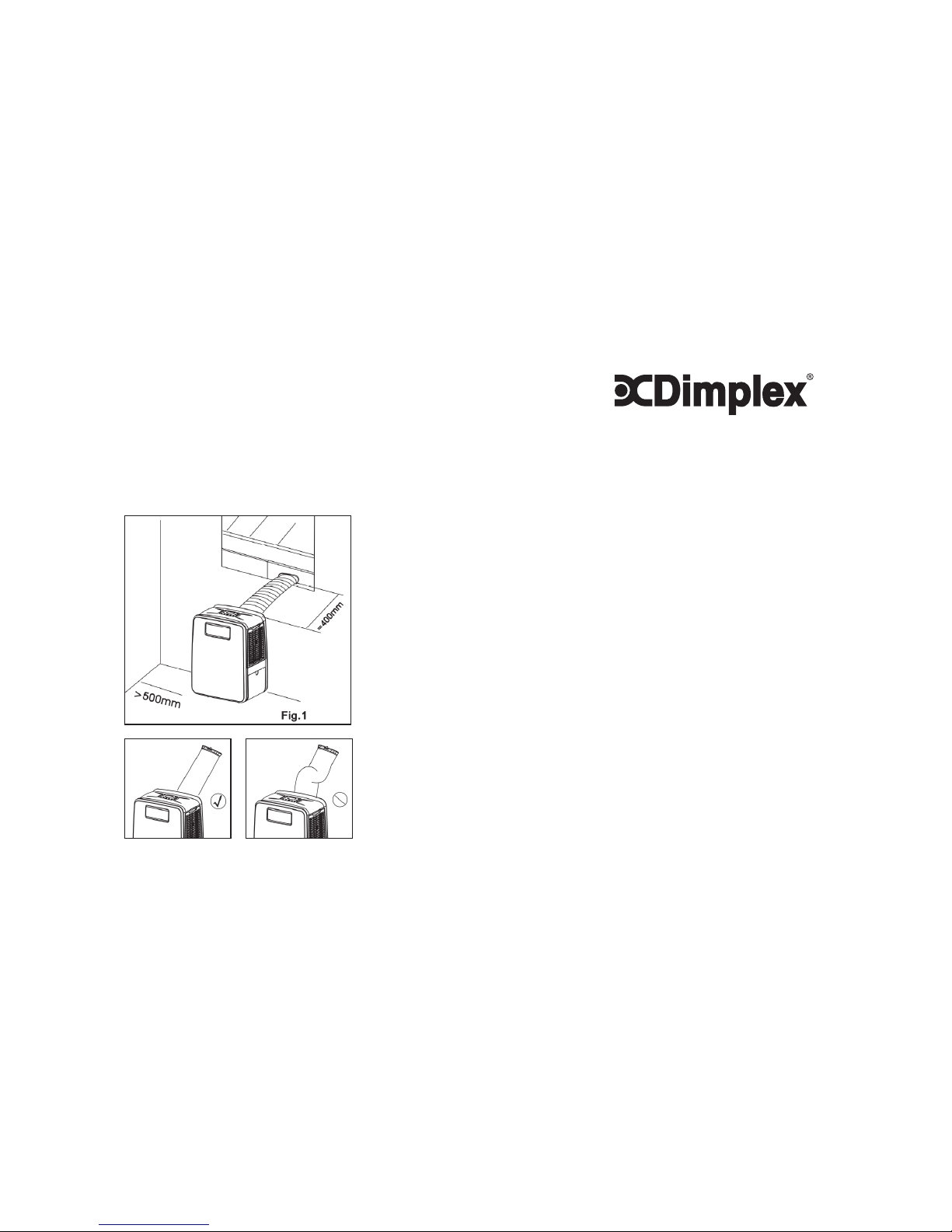
NOTES ON WINDOW KIT INSTALLATION
For effective cooling of a room (up to 11m2), please ensure that the
following steps are undertaken:
1. Extend the exhaust hose to a length of not more than 400mm. The exhaust
hose must be kept straight and must not be bent up or down.
2. A distance of 500mm minimum must be kept between the lter side of the
ComfortAir and wall or any other obstacles.
3. When the ComfortAir starts to defrost, the word “DF” will be displayed on
the LED screen.
CONGRATULATIONS ON YOUR
PURCHASE OF A
The ComfortAir is designed to keep you cool in the summer and dry in winter.
Its features include:
• A remote control
• Easy glide castors
• No installation required – just plug into any household power outlet
• Powerful refrigerated air system to cool small to medium sized rooms.
• Dehumidied and ltered air cycle to improve air quality.
• 24 hour programmable timer that can be used with either the air conditioning
or dehumidication setting
• Sleep/Quiet mode
COMFORTAIR 2In1
Page 4
6 7
1
2
3
6
7
4
5
CONTENTS
• ComfortAir main unit
• Remote control
• User manual
• Window Kit (exhaust hose can be
found in dehumidication tank)
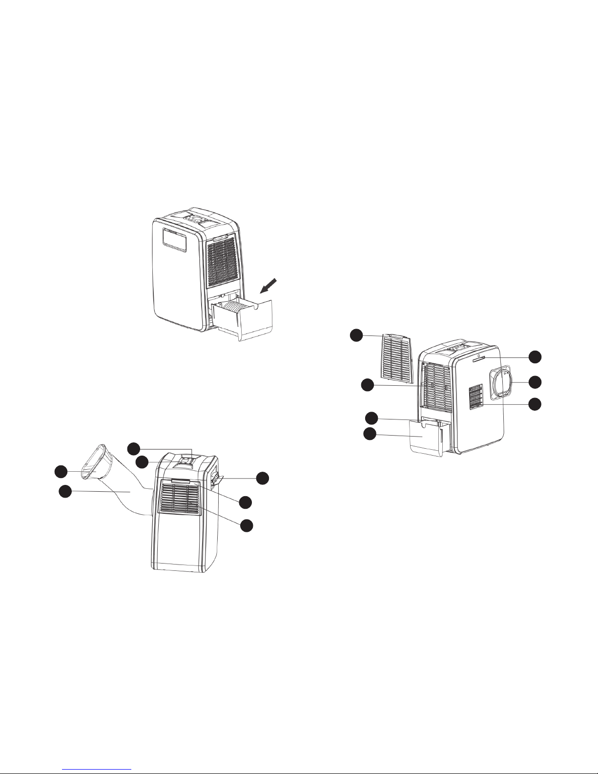
PARTS DIAGRAM
1. Control panel
2. Remote control receiver
3. Filter
4. Cool air outlet
5. Air inlet
6. Joint tube (to attach
to window kit)
7. Exhaust hose
PARTS DIAGRAM continued
8. Air lter
9. Air inlet
10. Hot air outlet joint
11. Hot air outlet
12. Remote control storage
13. Drain hole (remove plug to allow water to
drain into dehumidifying water tank)
14. Water tank
8
9
12
10
11
13
14
Page 5

8 9
CONTROL PANEL & DESCRIPTION
OF FUNCTIONS
1
2
3
6
7
8
9
45
10
1. POWER KEY
Press to turn ComfortAir “ON” or “OFF”
2. FUNCTION
Press to select dehumidifying, cooling or fan mode
3. SWING
Press this key and the outlet will oscillate. Press again to stop oscillation.
The outlet will close automatically when you turn the ComfortAir off.
4. INCREASE TEMPERATURE OR HUMIDITY (+)
During cooling function: press to raise the desired room temperature by 1°C.
The maximum temperature possible is 30°C.
During dehumidifying function: press to raise the desired humidity by 5%.
The maximum limit is 90%.
5. DECREASE TEMPERATURE OR HUMIDITY (-)
During cooling function: press to lower the desired room temperature by
1°C. The minimum temperature possible is 17°C.
During dehumidifying: press to lower the humidity by 5%. The minimum limit
is 30%. Or press until you see “CO” for Continuous Dehumidication.
6. SPEED
Press to select either LOW, HIGH or AUTO fan speed.
If “AUTO” is selected (during cooling function), the ComfortAir will
automatically select either “HIGH”, or “LOW” speeds depending on how
quickly the room needs cooling (i.e. based on the difference between the
desired temperature and ambient room temperature).
The ComfortAir will run on “HIGH” speed if the ambient room temperature
is higher than the desired temperature by 2°C or more and run on “LOW”
speed if less than 2°C.
7. SLEEP MODE
This function cools the room initially to help you get to sleep, but allows the
temperature to increase in the room to minimize energy usage.
1. While in cooling mode, press the SLEEP key
2. Set the desired temperature
After one hour, the desired temperature will increase by 1°C. It will then
increase by another degree after another hour.
Press the SLEEP key again to cancel the sleep setting.
CONTROL PANEL & DESCRIPTION
OF FUNCTIONS continued
Page 6

10 11
8. PROGRAMMABLE TIMER
TIMER-ON: The timer can be set to turn on the ComfortAir automatically
after a certain number of hours. To do this, press the “TIMER” key when on
stand-by mode to set the number of hours until you want the ComfortAir to
turn on.
TIMER-OFF: The timer can be set to turn off the ComfortAir automatically
after a certain number of hours. To do this, press the “TIMER” key when
the ComfortAir is operating to set the number of hours until you want the
ComfortAir to turn off.
9. LCD DISPLAY
The display indicates the current desired temperature, desired humidity
or the timer setting depending on the function selected. When the set
temperature, humidity or the timer is adjusted, the new setting is shown and
will ash for a few seconds. The display will then soon return to showing the
current ambient temperature or humidity.
The display is also used to show error codes should a fault occur, see
ERROR CODES.
10. REMOTE CONTROL INFRARED RECEIVER
FUNCTIONS
COOLING MODE
This setting will cool the room if you have an exhaust hose and window kit
installed. Use the temperature selection buttons to choose your desired room
temperature.
Alternatively, you can direct the cool air outlet towards a person to use it as a
personal cooler. In this mode, you do not need to use the exhaust hose and
window kit to ventilate.
DEHUMIDIFICATION
This setting will dehumidify your room by removing up to 30 litres of water
in your home’s atmosphere per day. This makes the ComfortAir suitable for
dehumidifying large households.
Dehumidify via the window kit
The ComfortAir can also dehumidify by sending excess moisture outside using
the exhaust hose and window kit. To do so, ensure the rubber cap
1
is placed in
the drainage outlet in the dehumidication tank.
If excess water is collected and cannot be ventilated, “E4” will be shown on the
display panel. You will need to remove the plug to drain the excess water.
Dehumidify via dehumidification tank
Remove the rubber plug in the dehumidication tank to allow dehumidied water
to drip into the tank.
Dehumidification note
If the room humidity is lower than the desired humidity by 2%, the ComfortAir will
stop dehumidifying. It will start dehumidifying again when the room humidity is
higher than the desired humidity by 2%.
1
Page 7

12 13
LCD SCREEN DISPLAY GUIDE
Sleep Fan Mode only
Timer Digital display
Child lock Temperature sign
Swing Humidity percentage
Alarm Hours on timer
Cooling Automatic fan speed
Dehumidifying Air speed indicator
REMOTE CONTROL FUNCTION
POWER On/Off switch
FUNC Function/“mode” selector
TIMER Set timer
AUTO Automatic fan speed
HI High fan speed
LOW Low fan speed
SLEEP Sleep mode selector
TEMP.
Temperature and humidity
selector
SWING Swing mode
Page 8

14 15
MAINTENANCE
PLEASE DISCONNECT THE POWER CORD BEFORE CLEANING
AIR FILTERS
1. The air lters located on both sides of the ComfortAir can be removed
simply by pulling the frame out.
2. Wash the lter with cool water (cooler than 40°C) every two weeks, and put
lter back after it has air-dried naturally.
CONDENSER/EVAPORATOR
Use a vacuum cleaner with a brush attachment to clean.
OUTER CASING
Wipe with a damp cloth and polish with a soft cloth.
PLACEMENT FOR USE
1. Because the ComfortAir exhausts hot air, please do not operate in narrow
environments.
2. Do not operate in direct sunlight as the ComfortAir may over heat and shut
down or the plastic may fade.
EXHAUST HOSE INSTALLATION
1. Take out the joint tube from the exhaust pipe (see picture 1) and x Part A
and Part B together.
2. Press the right side lter downwards (see picture 2) to take off the hot air
outlet joint.
3. Screw the exhaust pipe counterclockwise onto the joint tube (see arrow 3).
1
2
3
Page 9

16 17
4. Attach the pipe joint onto the ComfortAir (see arrow 4).
5. Screw the exhaust pipe counterclockwise on to the pipe joint (see arrow 5).
6. To remove the exhaust pipe, unscrew the exhaust pipe clockwise and take
it out (see arrow 6).
4
5
6
Install the Exhaust Hose and the Adjustable Window Slider Kit as depicted
in Fig.1 and Fig.1a.
Figure 1 - Vertical sliding
windows installation
Figure 1a - Horizontal
sliding windows
installation
TROUBLE SHOOTING
WINDOW KIT INSTALLATION
Problem Cause Trouble shooting
E1 Electrical short on both
temperature sensor and PCB.
Contact an electrician for repair.
E2 Electrical short of temperature
sensor copper tube and PCB
wiring.
Contact an electrician for repair.
E4 Indicates water tank full or
possibly incorrect placement
of drainage hose.
User needs to pull out the
rubber stopper which is located
within the water tank to drain
water held within the main unit.
Check that the drainage hose
has been positioned correctly.
Page 10

18 19
SPECIFICATION
(CE) N 842/2006:
R134a is a kind of uorinated greenhouse gases covered by the Kyoto Protocol.
R134a is total global warming potential (GWP) is 1430.
Model No. PC11-DM2A
Power Source 220-240V~50Hz
Rated Power (EN60335)
Cooling
610W
Cooling Capacity 1100W
Moisture Removed 30 litres/day
Humidifying capacity 0.2 L/H
Refrigerant R134a
Water Tank Capacity 2.6L
Dimensions (mm) 285W x 375D x 500H
This marking indicates that this product should not be disposed
with other household wastes throughout the EU. To prevent possible
hazards to the environment or human health from uncontrolled
waste disposal, please recycle it to prove the sustainable reuse of
material resources. Please ask return and collection systems or
contact the retailer where the product was purchased to return your
used device, they can recycle products safely.
Page 11

 Loading...