

Page 1
Glass Panel Heater
A
565
B
150
Min.
300 Min.
shelf
150 Min.
D
255 Min.
C
C D
GFP500 390 300
GFP750 390 300
GFP1000 560 300
GFP1500 630 300
DGP Series
Important InstructIons
When using electrical appliances, basic precautions should always
be followed to reduce the risk of re, electric shock, and injury to
persons, including the following:
Read all instructions before using this appliance.1.
The wall bracket supplied with the appliance must be used.2.
WARNING: This heater is hot when in use. To avoid burns, do
not let bare skin touch hot surfaces. Keep combustible materials,
such as furniture, pillows, bedding, papers, clothes, and curtains
at least 3 feet (0.9 m) from the front of the heater.
Extreme caution is necessary when any heater is used by 3.
or near children or invalids and whenever the heater is left
operating and unattended.
Do not use this heater in the immediate surroundings of a bath, 4.
shower, pool or other water basin. Check and observe all local
electrical and building codes for minimum clearances from
electrical switches and circuits before installing this unit.
If the heater is installed in a room containing a bath or shower, 5.
it must be installed in such a way that all controls are out of
reach of a person using the bath or shower.
Do not use outdoors.6.
A heater has hot and arcing or sparking parts inside. Do not 7.
use it in areas where highly ammable substances are used
(e.g. solvents, etc.) or stored.
To prevent a possible fire, do not block air intakes or exhaust 8.
in any manner. Do not use on soft surfaces, like a bed, where
openings may become blocked. Do not place material or
garments on the heater, or obstruct the air circulation around
the heater, for instance by curtains or furniture, as this could
cause overheating and a re risk.
Do not insert or allow foreign objects to enter any ventilation or 9.
exhaust opening as this may cause an electric shock or re, or
damage the heater.
Use this heater only as described in this manual. Any other use 10.
not recommended by the manufacturer may cause fire, electric
shock, or injury to persons.
Installation Instructions
Electrical Connection
Verify that the supply voltage is the same as that stated on the
heater (A.C supply only).
This heater is designed for use on a 208/240V 60Hz AC singlephase supply. Connection requires a supply wire that must consist
of two wires plus ground and have a rating capable of handling all
loads on the circuit.
Make all relevant electrical connections within an installed
junction box and ensure all wiring meets all local electrical and
building codes. Where local code requires the disconnection of all
ungrounded supply lines, a double pole isolating switch must be
tted to facilitate isolation.
Connection to the heater should be made using the provided tted
cable clamp assembly at the back of the heater to meet local code
requirements.
WARNING: Always use a qualied and licensed electrician for
all wiring and electrical connections. Improper wiring could lead
to a re hazard.
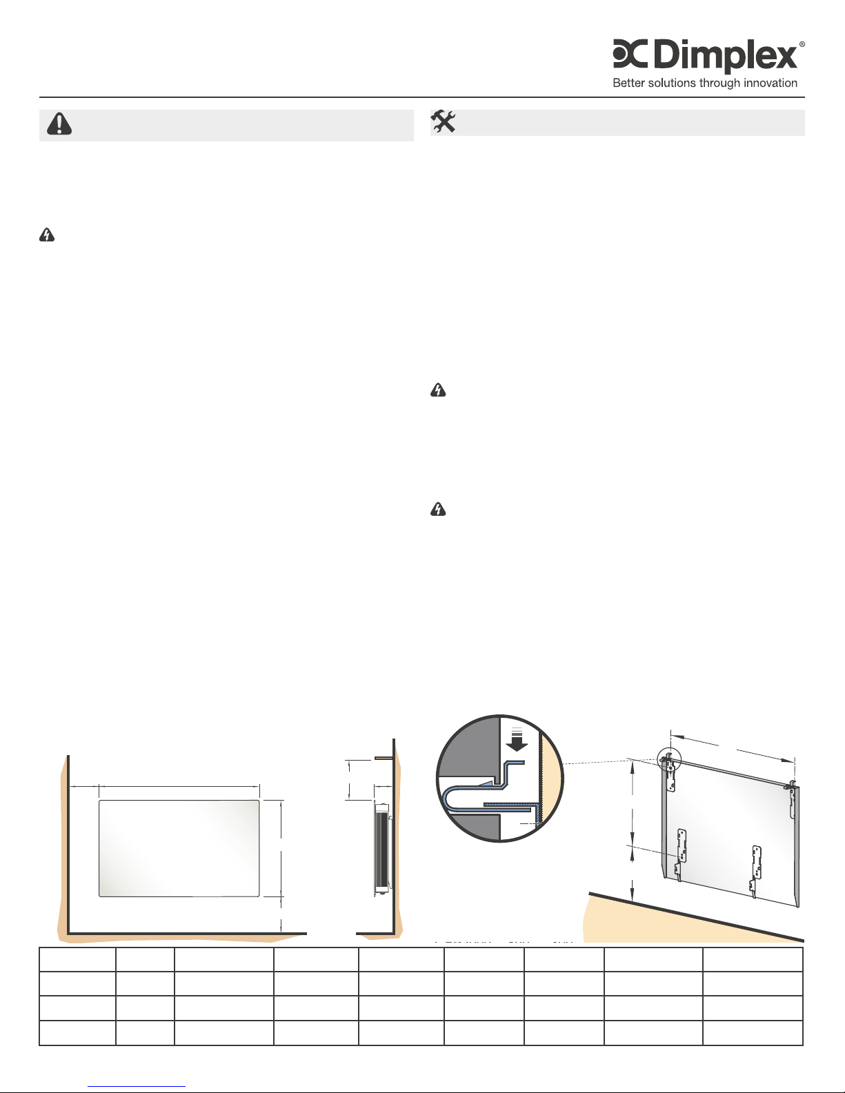
Wall Mounting
!
IMPORTANT: The wall bracket supplied with the appliance
must be used. The heater should be positioned observing the
minimum clearances stated around the heater (Figure 1).
WARNING: Do not locate the heater immediately below a xed
socket outlet or connection box.
Remove wall mounting bracket from the back of the heater by 1.
depressing the spring latch at the top of each bracket (Figure
2).
Fix the wall bracket securely to the wall through the four (4) 2.
screw holes provided.
Present the heater to the wall bracket and engage lower slots in 3.
the back with bracket.
Raise the heater to upright position and push the heater onto 4.
bracket to engage top latch.
Figure 2
SAVE THESE INSTRUCTIONS
Figure 1
Model(s) Volts Watts A (Figure 1) B (Figure 1) C (Figure 2) D (Figure 2) E (Figure 2) Weight
DGP1000-B
DGP1500-B
DGP2000-B
208 / 240 0.75 kW / 1 kW 700 mm / 27.6" 107 mm / 4.25" 560 mm / 22" 300 mm / 11.8" 255 mm / 10" MIN 14.8 kg / 32.6 lbs.
208 / 240 1.125 kW / 1.5 kW 770 mm / 30.3" 107 mm / 4.25" 630 mm / 24.8" 300 mm / 11.8" 255 mm / 10" MIN 16.4 kg / 36.2 lbs.
208 / 240 1.5 kW / 2.0 kW 840 mm / 37.0" 107 mm / 4.25" 800 mm / 31.5" 300 mm / 11.8" 255 mm / 10" MIN 19.5 kg / 42.9 lbs.
C
D
E
7210370100R01
INDGCAP7RG
Page 2
Operation
MAX
*
‘x’
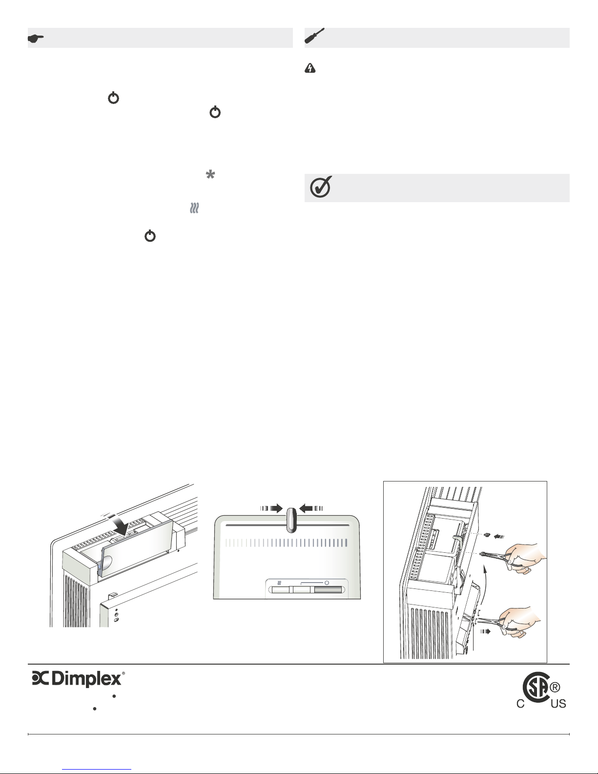
Switching the Heater On
The controls are located on the right hand side, on top of the
appliance. Lift ap to access the controls (Figure 3).
The button marked '
electronic thermostat. An indicator beside the '
when the unit is powered on.
Setting Desired Temperature
The heater is tted with an adjustable thermostat enabling
the room temperature to be controlled by adjusting the slider
accordingly (Figure 4). The minimum setting ‘
room temperature of approximately 5oC (41oF) and may be used
for protection against frost. The ‘MAX’ setting represents a room
temperature of approximately 30
the elements are actually heating.
Turn on the heater using the ‘
slider to the desired position. When the room temperature has
reached the desired level, the power to the elements will be
reduced, the heater will then maintain the room temperature at the
chosen level.
!
NOTE: Should your heater fail to come on when the thermostat
slider is at a low setting, this may be due to the room
temperature being higher than the thermostat setting.
Limiting the thermostat setting
Before wall mounting the product the installer may wish to limit
the heat selection slider movement for the operator. This may
be achieved by removing the two (2) plastic pins (refer to ‘x’ in
Figure 5) from the rear of the thermostat moulding using pliers and
inserting them in the preferred holes to limit the slider movement.
Safety - Overheat protection
For your safety this appliance is tted with a thermal cut-out. In
the event that the product overheats for some reason, the cut-out
prevents excessive temperatures on the product by cutting the
power to the heater. Once the heater has cooled down, it will reset
automatically, it will continue to cycle on and off automatically until
the reason for overheating is removed.
Figure 3
' controls the electricity supply to the
' button shows
‘ represents a
o
C. The ‘ ‘ symbol glows when
‘ button and move the thermostat
Figure 4
Maintenance
Cleaning
WARNING: Always disconnect from the power supply before
cleaning the heater.
Before commencing cleaning, turn off the heater and allow it to cool.
Disconnect the electricity supply to the appliance.
The outside can be cleaned by wiping it over with a soft damp cloth
and then dried. Do not use abrasive cleaning powders or furniture
polish, as this can damage the surface nish.
To release heater from the wall bracket for cleaning or redecoration,
depress latch on both brackets (see Figure 2) and hinge forward.
Warranty
The manufacturer warrants the heating elements and components of the
enclosed product against any defect in material or workmanship for a
period of two years. In full satisfaction of any claims under this warranty the
manufacturer will repair or replace without charge in its factory or in the eld
as it alone may decide any parts which in its operation are defective.
The manufacturer shall not be responsible for any transportation or shipping
costs in relation to such repair or replacement except as specically
assumed by it. Misuse of this product or repairs by persons other than the
manufacturer’s authorized personnel without the manufacturer’s written
approval, will void this warranty.
This warranty is in lieu of all other warranties or conditions whether express
or implied including but not limited to those of merchantability or tness for
purpose, and shall constitute the sole remedy of the purchaser and the sole
liability of the manufacturer in respect of the sale of the product whether
in the nature of breach or breach of fundamental term or of negligence or
otherwise.
The manufacturer shall not be liable for any special indirect or consequential
damages or for any damages resulting from removal or replacement of a
heater subject of a warranty claim without the manufacturer’s authorization.
This warranty is transferable by the original consumer purchaser of the
product. Any claims under this warranty must be submitted in writing to:
Dimplex North America Limited, 1367 Industrial Road, Cambridge Ontario,
N1R 7G8, Canada.
!
Note on Disposal: Do not dispose of the unit with general
household waste. The device must be taken to a local waste
disposal plant.
Figure 5
1367 Industrial Road Cambridge ON Canada N1R 7G8
1-888-346-7539 www.dimplex.com
In keeping with our policy of continuous product improvement, we reserve the right to make changes without notice.
© 2011 Dimplex North America Limited
www.dimplex.com2
 Loading...