

Page 1
DES 1821
DES 2427
DEE 1113
DEE 1821
DEE 2427
Montageanweisung
Deutsch
Installation Instructions
English
Instructions de montage
Francais
Montageanwijzing
Netherland
Instrukcja montażu
Polski
Elektronisch geregelter
Durchlauferhitzer
Electronically-regulated
Continuous-flow heater
12/15/A Bestell-Nr. / Order no. / No de commande: DEE_DES_1821_2427_Montage
Chauffe-eau instantané à
régulation électronique
Elektronisch geregelde
doorstroomgeiser
Elektronicznie regulo wanym podgrzewacz
przepływowy
Page 2

DE
Bestimmungsgemäßer Gebrauch
Dieses Gerät ist für den Haushalt oder für
haushaltsähnliche, nicht gewerbliche Anwendungen bestimmt. Haushaltsähnliche Anwendungen umfassen z. B. die Verwendung
in Mitarbeiterküchen von Läden, Büros, landwirtschaftlichen und anderen gewerblichen
Betrieben, sowie die Nutzung durch Gäste
von Pensionen, kleinen Hotels und ähnlichen
Wohneinrichtungen.
Sicherheitshinweise
Die Montageanleitung bitte sorgfältig
durchlesen, danach handeln und aufbewahren! Bei Weitergabe des Gerätes diese
Montageanleitung beilegen.
■ Das Gerät nur von einem Fachmann an-
schließen und in Betrieb nehmen lassen.
■ Das Gerät wie in Text und Bild beschrie-
ben montieren und bedienen. Wir übernehmen keine Haftung für Schäden, die
durch Nichtbeachtung dieser Anleitung
entstehen.
■ Beiliegende Wasseranschlussstutzen un-
bedingt verwenden und wie im Beiblatt
angegeben montieren. Sicherstellen, dass
im Kaltwasserzulauf ein Rückschlagventil
eingebaut wird.
■ Dieses Gerät ist für den Gebrauch bis zu
einer Höhe von 2 000 m über dem Meeresspiegel bestimmt.
■ Das Gerät nur in einem frostfreien Raum
installieren und lagern (Restwasser).
Stromschlaggefahr!
Schalten Sie im Fehlerfall sofort die
Netzspannung ab!
Vor dem Öffnen des Gerätes die Stromzufuhr zum Gerät unterbrechen.
Bei einer Undichtigkeit am Gerät sofort
die Kaltwasserleitung schließen.
■ Die gesetzlichen Vorschriften des jeweili-
gen Landes, des örtlichen Elektrizitäts-Versorgungsunternehmens und des Wasserwerkes müssen eingehalten werden.
■ Vorsicht: Geerdete Wasserleitungen kön-
nen das Vorhandensein eines Schutzleiters
vortäuschen.
■ Das Gerät muss dauerhaft an festverlegte
Leitungen angeschlossen werden. Der Lei-
tungsquerschnitt muss der zu installierenden Leistung entsprechen.
■ Zur Erfüllung der einschlägigen Sicher-
heitsvorschriften muss installationsseitig
eine allpolige Trennvorrichtung vorhanden
sein. Die Kontaktöffnung muss mindestens
3 mm betragen.
■ Das Gerät ist nur für den geschlossenen
(druckfesten) Betrieb geeignet.
■ Armaturen müssen für den Betrieb mit
geschlossenen (druckfesten) Durchlauferhitzern zugelassen sein.
■ Das Gerät kann an eine Kaltwasserleitung
angeschlossen oder mit vorgewärmtem
Wasser betrieben werden (nur bei DES).
Dazu technische Daten und Sonderzubehör beachten.
■ Der spezifische Wasserwiderstand darf
nicht unter 1 300 Ωcm liegen. Den Wasserwiderstand beim örtlichen Wasserversorger erfragen.
■ Das Gerät ist für den Anschluss an DVGW-
geprüfte Kunststoffrohre geeignet.
■ Das elektrische Anschlusskabel vor der
Montage spannungslos machen und die
Wasserzuleitung absperren!
■ Den Elektroanschluss erst nach dem
Wasseranschluss durchführen.
■ In der Rückwand nur die Öffnungen her-
stellen, die für die Montage benötigt werden. Bei erneuter Montage müssen die
unbenutzten Öffnungen wasserdicht verschlossen werden.
■ Spannungsführende Teile dürfen nach der
Montage nicht mehr berührbar sein.
■ Keine Scheuermittel oder anlösende Reini-
gungsmittel verwenden.
■ Keinen Dampfreiniger benutzen.
■ Der Durchlauferhitzer ist ein Gerät der
Schutzklasse I und muss an den Schutzleiter angeschlossen werden.
2
Page 3

DE
Herzlichen Glückwunsch zum Kauf dieses Geräts aus unserem
Hause Dimplex. Sie haben ein hochwertiges Produkt erworben, das Ihnen viel Freude bereiten wird.
Montageanleitung
Diese Montageanleitung gilt für verschiedene Gerätemodelle. Die Darstellung kann deshalb vom gekauften Gerät
abweichen.
■ Montieren Sie das Gerät wie im Bildteil beschrieben. Die
Bildseiten finden Sie in der Mitte der Anleitung. Beachten
Sie die Hinweise im Text.
Montage
I.
Auspacken/Haube abnehmen
■ Gerät auspacken und auf Transportschäden kontrollieren.
Liegt ein Schaden vor, Gerät nicht anschließen.
■ Lieferumfang kontrollieren: Gerät, Montagesatz mit
Beiblatt, Montageanleitung, Gebrauchsanleitung.
■ Verpackung und Altgerät umweltgerecht entsorgen.
■ Beim Abnehmen der Haube beachten: Die Haube ist
durch einen zentralen Verschluss hinter der Serviceklappe
fixiert.
II.
Montagevorbereitung
Wichtig: Nur den beiliegenden Montagesatz verwenden.
Die mitgelieferten Wasseranschlussstutzen müssen unbedingt eingebaut werden!
■ Wasserzuleitung absperren. Der elektrische Anschluss
(Anschlusskabel) muss spannungsfrei sein. Sicherungen
herausdrehen oder ausschalten.
■ Die Wasseranschlussstutzen nach der Anleitung auf dem
Beiblatt montieren.
■ Die Anschlussleitung kann wahlweise oben (X) oder
unten (Y) eingeführt werden.
■ Die Rückwand muss an der vorgesehenen Stelle auf dem
Kaltwasserstutzen aufliegen (Bild II., 8.).
III.
Wandmontage
■ Die Tülle muss das Anschlusskabel eng umschließen.
Wird sie bei der Montage beschädigt, müssen die Löcher
wasserdicht verschlossen werden.
■ Die Netzanschlussklemme kann oben (X) oder unten (Y)
montiert werden. Die Ummantelung des Anschlusskabels
muss mindestens 40 mm in das Gerät hineinragen.
■ Der Wandabstand ist variabel. So können Unebenheiten
der Wand ausgeglichen werden. Bei einem Wandabstand
von 8–16 mm die Distanzhalter einsetzen und die Verlängerung montieren (Bild III., 3. – 5.).
■ Das Gerät muss fest an der Wand montiert werden.
Befestigen Sie es gegebenenfalls an den unteren
Stellschrauben (Bild III., 6.).
IV.
Wasseranschluss
■ Den Wasseranschluss vornehmen, anschließend die Kalt-
wasserzuleitung öffnen.
■ Das Gerät muss entlüftet werden. Dazu Warmwasser-
hahn ganz öffnen und das Gerät 1 Minute lang spülen.
V.
Elektroanschluss/Montage
■ Nur bei Geräten mit Leistungsumschaltung:
Vor Anschluss der Leitungen an die Netzanschlussklemme
die Leistung mit dem Leistungsumschalter einstellen:
nominale Leistung links, reduzierte Leistung rechts
(Bild V., 1.) und die eingestellte Leistung am Typenschild
markieren.
■ Die Leitungen an der Netzanschlussklemme festschrauben.
■ Sicherheitsbegrenzer einschalten (Bild V., 3.)
■ Haube montieren (Bild V., 4. – 7.)
Installationshinweis
■ Die Installation nicht-steckerfertiger Geräte ist vom je-
weiligen Netzbetreiber oder von einem eingetragenen
Fachbetrieb vorzunehmen, der Ihnen auch bei der Einholung der Zustimmung des jeweiligen Netzbetreibers
für die Installation des Gerätes behilflich ist.
VI.
Inbetriebnahme
Das Gerät stimmt mit IEC 61000-3-12 überein.
Erstinbetriebnahme
■ Sicherungen einschalten.
■ Temperatur einstellen.
■ Startspülung: Warmwasserhahn ganz öffnen und mindes-
tens 1 Minute lang Wasser beziehen. Aus Sicherheitsgründen beginnt das Gerät erst danach mit dem Heizen.
Tipp: Startet das Gerät aufgrund von zu geringem Durchfluss
nicht, Perlator, Brausekopf oder Ähnliches zum Starten entfernen und Vorgang wiederholen.
■ Erklären Sie dem Benutzer die Bedienung des Gerätes.
VII.
Zusatzinformationen
■ Erreicht das Gerät aufgrund von zu geringem Wasser-
leitungsdruck in Ihrer Hausinstallation keinen genügenden Durchfluss, entfernen Sie den Durchflussbegrenzer
(Bild VII., 1. – 3.).
■ Vorrangschaltung für die Kombination mit Elektro-Spei-
cherheizgeräten:
Für den Betrieb mit Vorrangschaltung ist ein spezielles
Lastabwurfrelais BZ 45L21 (Sonderzubehör) erforderlich.
Andere, bereits vorhandene Lastabwurfrelais, ausgenommen elektronische Lastabwurfrelais, können Fehlfunktionen aufweisen (Bild VII., Schaltplan).
■ Bei Betrieb mit dem Lastabwurfrelais muss die Regelungs-
elektronik kodiert werden. Die Kodiernase auf der Elektronik entfernen (Bild VII., 4.).
3
Page 4
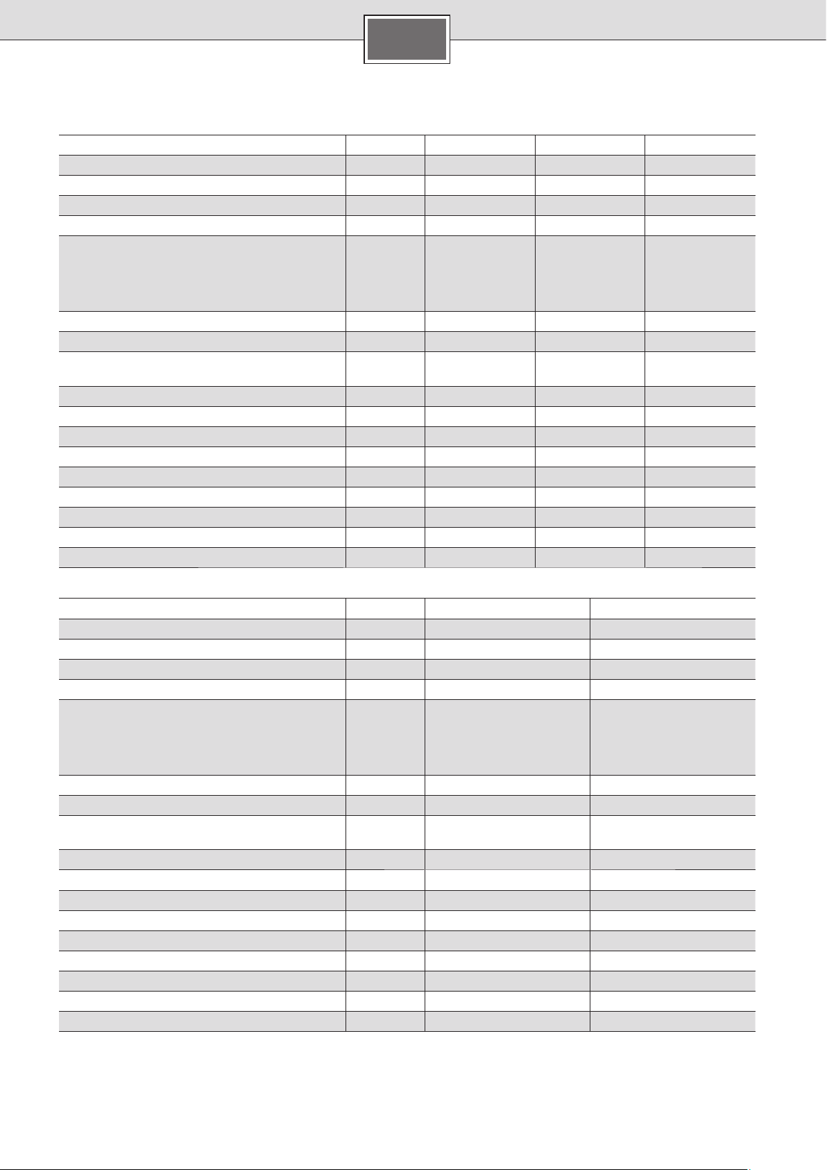
Technische Daten
Nennleistung
Nennspannung
Absicherung [A]
Mindestens Leitungsquerschnitt *
Warmwassermenge bei Nennleistung
bei Temperaturerhöhung von
12 °C auf 38 °C (ohne Durchflussmengenbegrenzer)
12 °C auf 38 °C (mit Durchflussmengenbegrenzer)
12 °C auf 60 °C
Einschaltmenge
Einschaltfließdruck **
Einsatzbereich in Wässern
Spezifischer elektrischer Widerstand bei 15 °C
Nenndruck
Maximal zulässige Zulauf-Temperatur
Maximale Netzimpedanz am Anschlussort
Energieeffizienzklasse
Lastprofil
Jahresenergieverbrauch
Täglicher Stromverbrauch
Schallleistungspegel
Warmwasserbereitungs-Energieeffizienz
DE
DEE 1113 DEE 1821 DEE 2427
[kW] 11/13 18/21 24/27
[V] 400 400 400
16/25
2
] 1,5/2,5 4 6
[mm
[l/min]
[l/min]
[l/min]
[l/min] 2,5 2,5 2,5
[MPa (bar)] 0,009 (0,09) 0,009 (0,09) 0,009 (0,09)
[Ωcm] ≥ 1 300 ≥ 1 300 ≥ 1 300
[MPa (bar)] 1,0 (10) 1,0 (10) 1,0 (10)
[°C] 20 20 20
[Ω] 0,433 0,067/0,104 0,067/0,104
[kWh] 477 479 479
[kWh] 2,196 2,203 2,207
[dB] 15 15 15
[%] 38,6 38,5 38,5
6,0/7,1
5
3,3/3,8
AAA
SSS
32 40
9,8/11,6
7,6
5,3/6,2
13,0/14,6
9,3
7,1/7,9
DES 1821 DES 2427
Nennleistung
Nennspannung
Absicherung [A] 32 40
Mindestens Leitungsquerschnitt *
Warmwassermenge bei Nennleistung
bei Temperaturerhöhung von
12 °C auf 38 °C (ohne Durchflussmengenbegrenzer)
12 °C auf 38 °C (mit Durchflussmengenbegrenzer)
12 °C auf 60 °C
Einschaltmenge
Einschaltfließdruck **
Einsatzbereich in Wässern
Spezifischer elektrischer Widerstand bei 15 °C
Nenndruck
Maximal zulässige Zulauf-Temperatur
Maximale Netzimpedanz am Anschlussort
Energieeffizienzklasse
Lastprofil
Jahresenergieverbrauch
Täglicher Stromverbrauch
Schallleistungspegel
Warmwasserbereitungs-Energieeffizienz
* In Abhängigkeit von der Verlegeart können auch größere Leitungsquerschnitte erforderlich sein.
** Hierzu kommt noch der Druckabfall an der Mischbatterie.
[kW] 18/21 24/27
[V] 400 400
2
]4 6
[mm
[l/min]
[l/min]
[l/min]
[l/min] 2,5 2,5
[MPa (bar)] 0,009 (0,09) 0,009 (0,09)
[Ωcm] ≥ 1 300 ≥ 1 300
[MPa (bar)] 1,0 (10) 1,0 (10)
[°C] 55 55
[Ω] 0,067/0,104 0,067/0,104
[kWh] 479 479
[kWh] 2,203 2,207
[dB] 15 15
[%] 38,5 38,5
9,8/11,6
7,6
5,3/6,2
AA
SS
13,0/14,6
9,3
7,1/7,9
4
Page 5

DE
Solarbetrieb
Nur für Geräte, die für Solarbetrieb geeignet sind:
Das Gerät erwärmt bereits vorgewärmtes Wasser auf max.
60 °C. Überschreitet der Kaltwasserzulauf die Temperatur von
55 °C, wird das Wasser nicht weiter erwärmt.
Wichtig: Die Kaltwasser-Zulauftemperatur darf nicht höher
als 55 °C sein!
Wird die Kaltwasser-Zulauftemperatur von 60 °C überschritten,
löst das Gerät eine Sicherheitsabschaltung aus. Deshalb muss
in der Hausinstallation ein Thermostatvormischer eingebaut
sein, der die Kaltwasser-Zulauftemperatur auf max. 55 °C
durch Zumischung von Kaltwasser begrenzt.
VIII.
Abmessungen
Sonderzubehör
■ Rohrbausatz DLE 02RBS zur Verwendung des Gerätes als
Untertischgerät
■ Vorrangschalter (Lastabwurfrelais) Siemens BZ 45L21 für
den Betrieb mit Vorrangschaltung
■ Montageset DLE 02AP: für Aufputzinstallation
Umweltgerecht entsorgen
Dieses Gerat ist entsprechend der europäischen
Richtlinie 2012/19/EU über Elektro- und Elektronikaltgeräte (waste electrical and electronic equipment – WEEE) gekennzeichnet.
Die Richtlinie gibt den Rahmen für eine EU-weit
gültige Rücknahme und Verwertung der Altgeräte
vor.
Über aktuelle Entsorgungswege bitte beim Fachhändler informieren.
Änderungen vorbehalten.
Produktdatenblatt nach Verordung (EU) Nr. 812/2013
Marke: Dimplex
Modellkennung: DEE 1113 / DEE 1821 / DEE 2427
Lastprofil: S
Energieeffizienzklasse: A
Energieeffizienzklasse: 38,6 / 38,5 / 38,5 %
Jährlicher Stromverbrauch: 477 / 479 / 479 kWh
Weitere Lastprofile, für deren Einsatz sich der Warmwasser-
bereiter eignet:
Lastprofil: –
Energieeffizienzklasse: –
Jährlicher Stromverbrauch: –
Temperatureinstellungen des Temperaturreglers
(ab Werk): 60 °C
Schallleistungspegel: 15 dB
Besondere Vorkehrungen, die bei Montage, Installation
oder Wartung des Gerätes zu treffen sind, entnehmen Sie
bitte der Montage- und Gebrauchsanleitung.
01/2016
Marke: Dimplex
Modellkennung: DES 1821 / DES 2427
Lastprofil: S
Energieeffizienzklasse: A
Energieeffizienzklasse: 38,5 / 38,5 %
Jährlicher Stromverbrauch: 479 / 479 kWh
Weitere Lastprofile, für deren Einsatz sich der Warmwasser-
bereiter eignet:
Lastprofil: M / M
Energieeffizienzklasse: 39,0 / 39,0 %
Jährlicher Stromverbrauch: 1 321 / 1 324 kWh
Temperatureinstellungen des Temperaturreglers
(ab Werk): 60 °C
Schallleistungspegel: 15 dB
Besondere Vorkehrungen, die bei Montage, Installation
oder Wartung des Gerätes zu treffen sind, entnehmen Sie
bitte der Montage- und Gebrauchsanleitung.
5
Page 6

EN
Intended Use
This appliance is intended for domestic use
or for household-based, non-commercial
applications. Household-based applications
include, e.g. usage in employees catering
facilities for shops, offices, agricultural and
other commercial operations, as well as
usage by guests of guest houses, small hotels
and similar residential establishments.
Safety information
Please read this installation instruction
manual carefully, then act accor dingly!
Store for future reference. These installation instructions must be included when
transferring this appliance to a new owner.
■ The appliance may only be connected
and put into operation by a qualified
professional.
■ Install and operate the appliance as de-
scribed in the text and illustrations. We do
not accept liability for damage resulting
from failure to heed these instructions.
■ The supplied water connection nozzles
must be used and installed as shown in
the supplementary sheets. Make sure that
a check valve is installed in the cold water
supply line.
■ This appliance is intended for use up to an
altitude of 2000 m above sea level.
■ The appliance may only be installed and
stored in a frost-free room (due to residual
water).
Risk of electric shock!
Switch off the mains voltage supply
immediately if a fault occurs.
Disconnect the power supply before
opening the appliance.
Immediately shut off the cold water
supply to the appliance should it leak.
■ The statutory regulations of the respective
country, as well as those of the local electricity and water suppliers, must be adhered to.
■ Caution: Earthed water pipes may give the
appearance of a connected protective earth.
■ The appliance must be permanently
connected to installed pipes. The conduc-
tor cross-section must comply with the
installed appliance power.
■ To guarantee compliance to relevant safety
regulations, an all-pole separator must
be fitted during installation. The contact
opening must be at least 3 mm.
■ The continuous-flow heater is only suitable
for closed (pressurised) operation.
■ The tap and outlet fittings must be ap-
proved for operation with closed (pressurised) continuous-flow heater systems.
■ The continuous-flow heater can be oper-
ated with cold or pre-warmed water (only
applies to DES). Observe the technical
data and the special accessories for this
purpose.
■ The water’s specific electrical resistivity
must not be less than 1 300 Ωcm. Ask the
local water utility company regarding the
electrical resistivity of the water.
■ The continuous-flow heater is suitable for
connection to DVGW-tested plastic pipes.
■ Disconnect the electrical connection
cable from the supply and shut off the
water supply before connecting the
appliance!
■ Connect the water supply and then
connect the electrical supply.
■ Only make the openings which are re-
quired for installation on the rear of the
appliance. If the appliance is reinstalled,
the unused openings must be provided
with watertight sealing.
■ Do not touch electrically live parts after
installation.
■ Do not use aggressive or abrasive cleaning
detergents!
■ Do not use a steam cleaner.
■ The continuous-flow heater is a Class I
appliance and must be connected to the
protective earth.
6
Page 7
EN
Congratulations on purchasing this Dimplex appliance. You
have acquired a top-quality product, which will give you a lot
of enjoyment.
Installation instructions
These installation instructions apply to various continuousflow heater appliance models. Therefore the illustrations
may deviate from the device you bought.
■ Install the appliance as shown in the illustrations. The
illustrations can be found in the centre of the instruction
manual. Observe the instructions in the text.
Installation
I.
Unpacking/Removing the cover
■ Unpack the appliance and check for transport damage. If
any components are damaged, then do not connect the
appliance.
■ Check that your appliance contains all components in-
cluded in the scope of delivery: appliance, installation
set with supplementary sheets, installation instructions,
operating instructions.
■ Please dispose of the packaging and the old appliance in
an environmentally-friendly manner.
■ When removing the cover, please note the following:
The cover is fastened by a central closure behind the
service flap.
II.
Preparations for installation
Important: Only use the supplied installation set.
The supplied water connection nozzles must be installed!
■ Shut off water supply. The electrical connection (connec-
tion cable) must be disconnected from the power supply.
Unscrew the fuse or switch off the circuit breaker.
■ Install the water connection nozzles according to the in-
structions on the supplementary sheet.
■ The electrical connection cable can either be guided in at
the top (X) or bottom (Y).
■ The rear panel must lie against the cold water connection
nozzle in the position provided for such (Fig. II., 8.).
III.
Wall mounting
■ The grommet must tightly surround the connection cable.
If it is damaged during mounting, the openings must be
provided with watertight sealing.
■ The electrical supply terminal can be fitted at the top (X)
or bottom (Y). The sheath of the connection cable must
extend for at least 40 mm into the appliance.
■ The distance to the wall is variable. You can compensate
for any unevenness of the wall’s surface. With a distance
to the wall of 8–16 mm, insert the spacer and install the
extender (Fig. III., 3. – 5.).
■ The appliance must be mounted securely on the wall. If nec-
essary, attach it at the lower adjustable screws (Fig. III., 6.).
IV.
Water connection
■ Connect the water supply, then open the cold water supply.
■ The appliance must be vented. To do so, open the
warm water tap fully and flush out the appliance
thoroughly for 1 minute.
V.
Electrical connection/Mounting
■ Only for appliances with power selector switches:
Set the power using the power selector switch before
connecting the wires to the mains connection terminal:
Nominal output power left, reduced output right
(Fig. V., 1.) and the set output marked on the ratings plate.
■ Screw the wires tightly into the mains connection terminal.
■ Switch on the safety limiter (Fig. V., 3.)
■ Install the cover (Fig. V., 4. – 7.).
Installation note
■ The installation of non plug-in ready appliances must
be undertaken by the respective utility operator or by
a qualified specialist company, who can also assist you
when you are requesting the approval of the utility
company for installation of the appliance.
VI.
Startup
The device is compliant to IEC 61000-3-12.
First start-up
■ Switch on the fuses.
■ Setting the temperature.
■ Initial rinsing: Open the warm water tap fully and allow
water to flow for at least 1 minute. Only then (for safety
reasons) will the appliance begin to heat.
Tip: Should the appliance not start because of a reduced
flow-rate, remove the perlator, shower head or similar before
start and repeat the process.
■ Explain the operation of the appliance to the user.
VII.
Additional information
■ If the appliance does not have sufficient water flow due
to low water line pressure in your domestic plumbing system, remove the flow-rate limiter (Fig. VII., 1. – 3.).
■ Priority circuit for the combination with electrical storage
heaters:
For operation with a priority circuit, a special load shedding relay BZ 45L21 (special accessory) is required. Other
existing load shedding relays, with the exception of electronic load shedding relays, may malfunction (Fig. VII.,
Wiring diagram).
■ The control electronics must be coded when operated
with a load shedding relay. Remove the keying nose on
the electronics (Fig. VII., 4.).
7
Page 8
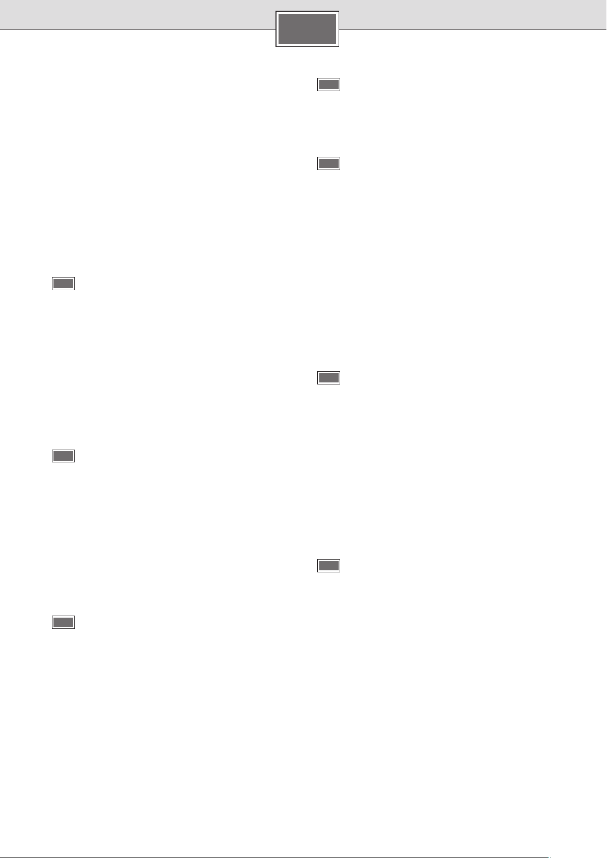
Technical data
Rated output
Rated voltage
Fuse protection [A]
Minimum conductor cross-section *
Warm water flow at rated output
with temperature increase from
12 °C to 38 °C (without flow-rate limiter)
12 °C to 38 °C (with flow-rate limiter)
12 °C to 60 °C
Start-up flow
Start-up flow pressure **
Application area in water
specific electric resistance at 15 °C
Rated pressure
Maximum permissible supply temperature
Maximum mains impedance at connection point
Energy efficiency class
Load profile
Annual energy consumption
Daily energy consumption
Sound power level
Hot water heating energy efficiency
EN
DEE 1113 DEE 1821 DEE 2427
[kW] 11/13 18/21 24/27
[V] 400 400 400
16/25
2
] 1.5/2.5 4 6
[mm
[l/min]
[l/min]
[l/min]
[l/min] 2.5 2.5 2.5
[MPa (bar)] 0.009 (0.09) 0.009 (0.09) 0.009 (0.09)
[Ωcm] ≥ 1 300 ≥ 1 300 ≥ 1 300
[MPa (bar)] 1.0 (10) 1.0 (10) 1.0 (10)
[°C] 20 20 20
[Ω] 0.433 0.067/0.104 0.067/0.104
[kWh] 477 479 479
[kWh] 2.196 2.203 2.207
[dB] 15 15 15
[%] 38.6 38.5 38.5
6.0/7.1
5
3.3/3.8
AAA
SSS
32 40
9.8/11.6
7.6
5.3/6.2
13.0/14.6
9.3
7.1/7.9
DES 1821 DES 2427
Rated output
Rated voltage
Fuse protection [A] 32 40
Minimum conductor cross-section *
Warm water flow at rated output
with temperature increase from
12 °C to 38 °C (without flow-rate limiter)
12 °C to 38 °C (with flow-rate limiter)
12 °C to 60 °C
Start-up flow
Start-up flow pressure **
Application area in water
specific electric resistance at 15 °C
Rated pressure
Maximum permissible supply temperature
Maximum mains impedance at connection point
Energy efficiency class
Load profile
Annual energy consumption
Daily energy consumption
Sound power level
Hot water heating energy efficiency
* Larger cable cross-sections may be required depending on the connection configuration.
** The pressure loss on the mixer must also be added.
[kW] 18/21 24/27
[V] 400 400
[mm2]4 6
[l/min]
[l/min]
[l/min]
[l/min] 2.5 2.5
[MPa (bar)] 0.009 (0.09) 0.009 (0.09)
[Ωcm] ≥ 1 300 ≥ 1 300
[MPa (bar)] 1.0 (10) 1.0 (10)
[°C] 55 55
[Ω] 0.067/0.104 0.067/0.104
[kWh] 479 479
[kWh] 2.203 2.207
[dB] 15 15
[%] 38.5 38.5
9.8/11.6
7.6
5.3/6.2
AA
SS
13.0/14.6
9.3
7.1/7.9
8
Page 9
EN
Solar heated
Only for appliances that are suitable for solar heating
systems:
The appliance can only heat prewarmed water to a max.
of 60 °C. If the cold water supply exceeds a temperature of
55 °C, the water will not be warmed any further.
Important: The cold water supply temperature must not be
higher than 55 °C!
If the cold water supply exceeds a temperature of 60 °C,
a circuit breaker will trigger and shut the appliance off.
Therefore, the residential plumbing must be equipped with
a thermostatic premixer that will limit the cold water supply
temperature to a max. of 55 °C by appropriately mixing in
cold water.
VIII.
Dimensions
Special accessories
■ Pipe kit DLE 02RBS for use of the appliance as an under-
sink appliance
■ Priority switch (load shedding relay) Siemens BZ 45L21:
for operation with a priority circuit
■ Mounting kit DLE 02AP: for surface mount installation
Environmentally-friendly disposal
This appliance is labelled in accordance with European Directive 2012/19/EU concerning used electrical and electronic appliances (waste electrical
and electronic equipment – WEEE).
The guideline determines the framework for the
return and recycling of used appliances as applicable throughout the EU.
Please ask your specialist retailer about current
disposal facilities.
Subject to change without notice.
Product fiche concerning the “Commission delegated regulation (EU) No 812/2013”
Trade mark: Dimplex
Model Identifier: DEE 1113 / DEE 1821 / DEE 2427
Load profile: S
Energy efficiency class: A
Energy efficiency class: 38.6 / 38.5 / 38.5 %
Annual electricity consumption: 477 / 479 / 479 kWh
Further possible load profiles:
Load profile: –
Energy efficiency class: –
Annual electricity consumption: –
Thermostat temperature settings (factory setting): 60 °C
Sound power level: 15 dB
All specific precautions that shall be taken when the water
heater is assembled, installed or maintained are descibed
in the installation and operating instructions.
01/2016
Trade mark: Dimplex
Model Identifier: DES 1821 / DES 2427
Load profile: S
Energy efficiency class: A
Energy efficiency class: 38.5 / 38.5 %
Annual electricity consumption: 479 / 479 kWh
Further possible load profiles:
Load profile: M / M
Energy efficiency class: 39.0 / 39.0 %
Annual electricity consumption: 1 321 / 1 324 kWh
Thermostat temperature settings (factory setting): 60 °C
Sound power level: 15 dB
All specific precautions that shall be taken when the water
heater is assembled, installed or maintained are descibed
in the installation and operating instructions.
9
Page 10

FR
Utilisation conforme
Cet appareil est conçu pour l’usage domestique ou pour des applications identiques, non
commerciales. Des applications identiques à
l’usage domestique sont par exemple l’utilisation dans des cuisines pour employés dans des
magasins, bureaux, entreprises agricoles ou
autres entreprises industrielles, ainsi que l’utilisation par des clients de pensions, petits hôtels
et autres locaux d’habitation identiques.
Consignes de sécurité
Lire attentivement cette notice de montage, agir en conséquence et la conserver !
Si l’appareil est revendu, il doit toujours
être accompagné de la présente notice de
montage.
■ Ne faire raccorder et mettre en service
l’appareil que par un technicien
spécialisé.
■ Monter et utiliser l’appareil comme indiqué
dans le texte et à l’écran. Nous n’assumons
aucune garantie pour les risques susceptibles de survenir en cas de non-respect de
cette notice.
■ Obligatoirement utiliser les raccords d’eau
fournis en annexe et les monter comme
indiqué dans la fiche complémentaire. S’assurer qu’un clapet anti-retour est monté
dans l’arrivée d’eau froide.
■ Cet appareil est destiné à une utilisation
jusqu’à une hauteur maximale de 2 000 m
au-dessus du niveau de la mer.
■ Toujours installer et stocker l’appareil dans
une pièce à l’abri du gel (eau résiduelle).
Danger de choc électrique !
En cas d’erreur, déconnectez immédiatement la tension du secteur.
Couper l’alimentation en courant
avant d’ouvrir l’appareil.
En cas de fuite sur l’appareil, immédiatement couper l’alimentation en eau
froide.
■ Respectez les prescriptions légales en
vigueur dans votre pays ainsi que celles recommandées par les compagnies locales/
nationales distributrices d’électricité et
d’eau et applicables dans votre localité.
■ Le chauffe-eau instantané est un appa-
reil qui répond à la classe de protection I.
Il doit être raccordé au fil de terre.
■ Exemple : les conduites d’eau mises à la
terre peuvent simuler la présence d’un fil de
terre.
■ L’appareil doit être raccordé de manière
durable aux conduites d’eau posées de
manière fixe. La section de câble doit
correspondre à la puissance à installer.
■ Afin de respecter les prescriptions de sécu-
rité applicables, l’installation doit comporter un dispositif de coupure tous pôles.
L’espace coupe-circuit entre les contacts
doit s’élever à 3 mm minimum.
■ Le chauffe-eau est conçu uniquement pour
fonctionner en circuit fermé (résistant à la
pression).
■ La robinetterie doit pouvoir s’utiliser avec des
chauffe-eau fermés (résistants à la pression).
■ Le chauffe-eau instantané peut être raccor-
dé à une conduite d’eau froide ou être exploité avec l’eau préchauffée (uniquement
pour DES). Pour ce, respecter les données
techniques et les accessoires spéciaux.
■ La résistance spécifique de l’eau ne doit
pas être inférieure à 1 300 Ωcm. Demander
la valeur de la résistance de l’eau à l’opérateur local de distribution d’eau.
■ Le chauffe-eau peut s’utiliser avec de la
tuyauterie en matière plastique certifiée
DVGW.
■ Avant le montage, mettez le câble
d’alimentation électrique hors tension
et coupez l’arrivée d’eau !
■ Procédez d’abord au raccordement de
l’eau, puis au raccordement électrique.
■ Réalisez dans la paroi arrière uniquement
les ouvertures nécessaires au montage.
Lors du remontage, bouchez les ouvertures
inutilisées afin de les rendre étanches.
■ Une fois le montage terminé, les pièces
électroconductrices doivent être impossibles à toucher.
■ Ne pas utiliser de détergents agressifs ou
solvants.
■ Ne pas utiliser de nettoyeur à vapeur.
10
Page 11

FR
La société Dimplex vous félicite pour l’achat de son appareil. Vous avez acheté un produit de qualité élevée qui vous
apportera beaucoup de plaisir.
Instructions de montage
La présente notice de montage est valable pour différents
types d’appareil. Les illustrations peuvent en conséquence
différer de l’appareil acheté.
■ Monter l’appareil comme décrit dans la partie images. La
partie avec les illustrations figurent au milieu de la notice
d’utilisation. Respectez les consignes du texte.
Montage
I.
Déballage/enlèvement du capot
■ Déballez l’appareil et vérifiez s’il n’a pas subi de dégâts
pendant le transport. Si un dégât est constaté, ne pas
raccorder l’appareil.
■ Contrôler l’étendue de livraison : appareil, kit de montage
avec fiche complémentaire, notice de montage, notice
d’utilisation.
■ Éliminer l’emballage et l’appareil usé de manière favorable
à l’environnement.
■ Pour retirer le capot, tenir compte des points suivants :
Le capot est fixé à l’arrière du clapet de service au moyen
d’une fermeture centrale.
II.
Préparation du montage
Important : utiliser impérativement le jeu de montage joint.
Les tubulures de raccordement d’eau livrées doivent être
impérativement montées !
■ Coupez l’arrivée d’eau. Le raccord électrique (câble de
raccordement) doit être mise hors tension. Dévissez ou
désenclenchez les fusibles.
■ Monter les raccords d’eau selon les indications fournies
dans la fiche complémentaire.
■ La conduite d’alimentation en eau peut être introduite soit
en haut (X) ou en bas (Y).
■ La paroi arrière doit reposer sur le raccord d’eau froide à
l’endroit prévu (Fig. II., 8.).
III.
Montage mural
■ La gaine doit bien enserrer le cordon d’alimentation.
Si elle a été endommagée pendant le montage, bouchez
les trous pour les rendre étanches à l’eau.
■ La borne de branchement au secteur peut être montée en
haut (X) ou en bas (Y). La gaine du câble d’alimentation
doit pénétrer au moins de 40 mm dans l’appareil.
■ L’écart par rapport au mur est variable. Vous pouvez ainsi
compenser les inégalités du mur. Si l’écart par rapport au
mur est de 8–16 mm, utiliser les espaceurs et monter la
rallonge (Fig. III., 3. – 5.).
■ Le montage de l’appareil au mur doit être fixe. Si néces-
saire, fixer l’appareil au moyen des vis de réglage inférieures (Fig. III., 6.).
IV.
Raccordement de l’eau
■ Raccorder l’eau et puis ouvrir la conduite d’alimentation
en eau froide.
■ L’appareil doit être purgé. Ouvrir à ce but complète-
ment le robinet d’eau chaude et rincer l’appareil pendant 1 minute.
V.
Branchement électrique/montage
■ Uniquement pour appareils avec commutateur de
puissance :
Avant le raccordement des câbles à la borne de branchement au secteur, régler la puissance à l’aide du commutateur de puissance : marquer la puissance nominale
à gauche, la puissance réduite à droite (Fig. V., 1.) et la
puissance configurée sur la plaque signalétique.
■ Visser à fond les conduites sur la borne de branchement
au secteur.
■ Activer le limiteur de sécurité (Fig. V., 3.).
■ Monter le capot (Fig. V., 4. – 7.)
Remarque sur l’installation
■ L’installation d’appareils pas prêts au branchement
doit être effectuée par l’exploitant de réseau ou par
une entreprise spécialisée habilitée, laquelle vous aide
également à obtenir l’accord de l’exploitant de secteur
respectif pour l’installation de l’appareil.
VI.
Mise en service
L’appareil est conforme à la norme CEI 61000-3-12.
Première mise en service
■ Réenclencher les fusibles.
■ Régler la température.
■ Rinçage au démarrage : ouvrir complètement le robinet
d’eau chaude et tirer de l’eau pendant au moins 1 minute.
Pour des raisons de sécurité, l’appareil ne commence pas
à chauffer avant.
Astuce : si l’appareil ne démarre pas en raison d’un débit
trop faible, retirer le brise-jet, la pomme de douche ou tout
élément similaire pour le démarrage et répéter le processus.
■ Expliquer la manipulation de l’appareil à l’utilisateur.
VII.
Informations supplémentaires
Si le débit de l’appareil n’est pas suffisant en raison
d’une pression d’eau trop faible dans les conduites d’eau
de l’installation domestique, retirer le limiteur de débit
(Fig. VII., 1. – 3.).
■ Commutation prioritaire si le chauffe-eau doit être combiné
à des appareils de chauffage électrique à accumulation :
Pour l’exploitation avec une commutation prioritaire, un
relais de délestage brusque spécial BZ 45L21 (accessoires
spéciaux) s’impose. Les autres relais de délestage brusque
déjà existants, exceptés les relais de délestage électroniques, peuvent présenter des fonctions erronées (Fig. VII.,
Schéma de connexions).
■ Lors d’une exploitation avec le relais de délestage brusque,
l’électronique de réglage doit être codée. Retirer le bec de
codage sur le matériel électronique (Fig. VII., 4.).
11
Page 12

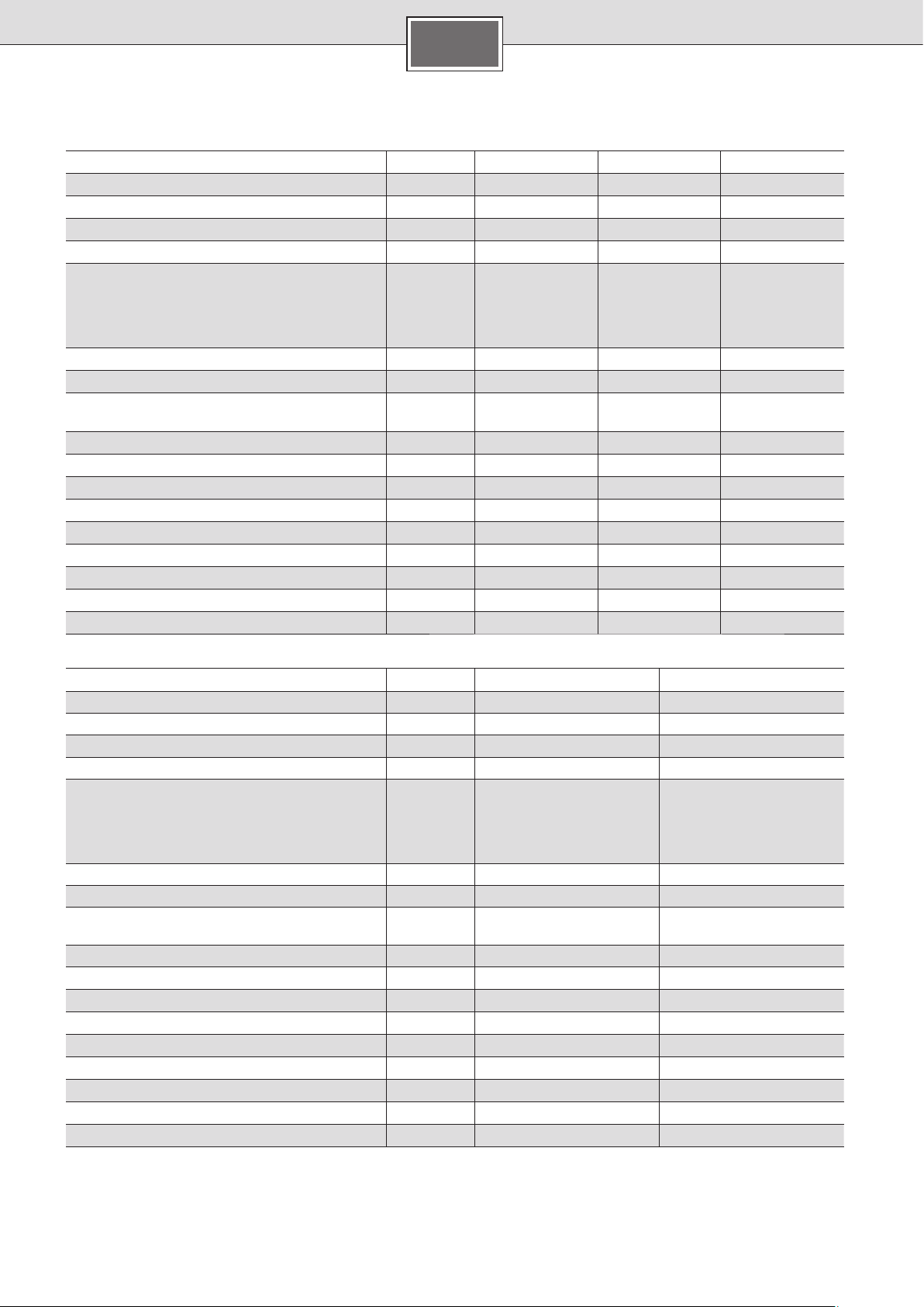
Données techniques
Puissance nominale
Tension nominale
Protection par fusibles [A]
Section de câble minimale *
Débit d’eau chaude pour puissance nominale
pour une augmentation de température de
12 °C à 38 °C (sans limiteur de débit)
12 °C à 38 °C (avec limiteur de débit)
12 °C à 60 °C
Débit à l’enclenchement
Pression d’écoulement à l’enclenchement **
Rayon d’action dans l’eau
Résistance électrique spécifique à 15 °C
Pression nominale
Température maximale admissible à l’entrée
Impédance de secteur maximale sur le lieu
de raccordement
Classe d’efficacité énergétique
Profil de soutirage
Consommation annuelle d’énergie
Consommation quotidienne de courant
Niveau de puissance acoustique
Efficacité énergétique de la préparation
d’eau chaude
FR
DEE 1113 DEE 1821 DEE 2427
[kW] 11/13 18/21 24/27
[V] 400 400 400
16/25
2
] 1,5/2,5 4 6
[mm
[l/min]
[l/min]
[l/min]
[l/min] 2,5 2,5 2,5
[MPa (bar)] 0,009 (0,09) 0,009 (0,09) 0,009 (0,09)
[Ωcm] ≥ 1 300 ≥ 1 300 ≥ 1 300
[MPa (bar)] 1,0 (10) 1,0 (10) 1,0 (10)
[°C] 20 20 20
[Ω] 0,433
[kWh] 477 479 479
[kWh] 2,196 2,203 2,207
[dB] 15 15 15
[%] 38,6 38,5 38,5
6,0/7,1
5
3,3/3,8
AAA
SSS
32 40
9,8/11,6
7,6
5,3/6,2
0,067/
0,104
13,0/14,6
9,3
7,1/7,9
0,067/
0,104
DES 1821 DES 2427
Puissance nominale
Tension nominale
Protection par fusibles [A] 32 40
Section de câble minimale *
Débit d’eau chaude pour puissance nominale
pour une augmentation de température de
12 °C à 38 °C (sans limiteur de débit)
12 °C à 38 °C (avec limiteur de débit)
12 °C à 60 °C
Débit à l’enclenchement
Pression d’écoulement à l’enclenchement **
Rayon d’action dans l’eau
Résistance électrique spécifique à 15 °C
Pression nominale
Température maximale admissible à l’entrée
Impédance de secteur maximale sur le lieu
de raccordement
Classe d’efficacité énergétique
Profil de soutirage
Consommation annuelle d’énergie
Consommation quotidienne de courant
Niveau de puissance acoustique
Efficacité énergétique de la préparation
d’eau chaude
* De plus grandes sections de câbles peuvent éventuellement être nécessaires en fonction du type de pose.
** La perte de pression au mitigeur doit y être ajoutée.
[kW] 18/21 24/27
[V] 400 400
2
]4 6
[mm
[l/min]
[l/min]
[l/min]
[l/min] 2,5 2,5
[MPa (bar)] 0,009 (0,09) 0,009 (0,09)
[Ωcm] ≥ 1 300 ≥ 1 300
[MPa (bar)] 1,0 (10) 1,0 (10)
[°C] 55 55
[Ω]
[kWh] 479 479
[kWh] 2,203 2,207
[dB] 15 15
[%] 38,5 38,5
9,8/11,6
7,6
5,3/6,2
0,067/
0,104
AA
SS
13,0/14,6
9,3
7,1/7,9
0,067/
0,104
12
Page 13

Page 14

I.
1a.
1b.
4.
3.
2b.
4.
2a.
ca. 30°
5.
Page 15

1.
II.
6.
2.
2.
Y
8.
3a.
X
XY
Ø 6 mm
ca. 96
70
b+c
7.
a
b
4.
c
b
5.
3b.
ca. 72
44
388
332
100
c
Page 16

III.
2.
X
Y
1.
1.
a
0 mm
min. 40 mm
X
ca. 2 – 8 mm
40 mm
X
Y
3.
ca. 8 – 16 mm
Ø 6 mm
40 mm
5.
4.
6.
Page 17

2.
IV.
3.
3.
1.
4.
5.
1 Minute entlüften!
Vent for one minute!
Purger pendant une
minute !
8.
warm heet
hot gorący
chaude
6. 7.6.
1 minuut ontluchten!
Odpowietrzyć –
1 minutę!
Page 18

3.
3.
PE L1 L2 L3
PEL1L2L3
V.
13 kW 11 kW
21 kW 18 kW
27 kW 24 kW
1.
RESET
min. 40 mm
2.
X
2. Y
TX20
TX20
4.
5.
6.
7.
VI.
4.
2.
1.
Page 19

1.
VII.
3.
2.
PE
3
L 3
L 2
L 1
PE
4.
21
Page 20

VIII.
472
20
236
100
33242388
(G
21,3
1
99
A)
2
115
Page 21

FR
Mode solaire
Uniquement pour appareils appropriés pour le mode
solaire :
L’appareil chauffe de l’eau préchauffée au maximum jusqu’à
60 °C. Si l’arrivée d’eau froide dépasse la température de
55 °C, l’eau ne continue pas à être réchauffée.
Important : La température d’arrivée de l’eau froide ne doit
pas être supérieure à 55 °C !
Si la température d’arrivée de l’eau froide de 60 °C est dépassée, l’appareil déclenche une déconnexion de la sécurité.
C’est la raison pour laquelle un prémélangeur à thermostat
doit être monté dans l’installation domestique, qui limite la
température d’arrivée d’eau froide à maxi 55 °C en mélangeant l’eau froide.
VIII.
Dimensions
Accessoires spéciaux
■ Assemblage tubulaire DLE 02RBS pour un montage sous
évier de l’appareil
■ Commutateur prioritaire (relais de délestage brusque)
Siemens BZ 45L21 : pour l’exploitation avec commutation
prioritaire
■ Kit de montage DLE 02AP : pour une installation sur crépi
Élimination favorable à
l’environnement
Cet appareil est marqué selon la directive européenne 2012/19/UE relative aux appareils électriques et électroniques usagés (waste electrical
and electronic equipment – WEEE).
La directive définit le cadre pour une reprise et une
récupération des appareils usagés applicables dans
les pays de la CE.
S’informer auprès du revendeur sur la procédure
actuelle de recyclage.
Fiche de produit selon règlement (UE) nº 812/2013
Marque : Dimplex
Référence commerciale : DEE 1113 / DEE 1821 / DEE 2427
Profil de soutirage : S
Classe d’efficacité énergétique : A
Classe d’efficacité énergétique : 38,6 / 38,5 / 38,5 %
Consommation annuelle d’électricité : 477 / 479 / 479 kWh
Autres profils de soutirage pour lesquels l’utilisation du
chauffe-eau est appropriée :
Profil de soutirage : –
Classe d’efficacité énergétique : –
Consommation annuelle d’électricité : –
Réglages du thermostat (départ usine) : 60 °C
Niveau de puissance acoustique : 15 dB
Pour les précautions particulières nécessaires pour le
montage, l’installation ou l’entretien du dispositif, se
référer aux instructions de montage et d’utilisation.
Marque : Dimplex
Référence commerciale : DES 1821 / DES 2427
Profil de soutirage : S
Classe d’efficacité énergétique : A
Classe d’efficacité énergétique : 38,5 / 38,5 %
Consommation annuelle d’électricité : 479 / 479 kWh
Autres profils de soutirage pour lesquels l’utilisation du
chauffe-eau est appropriée :
Profil de soutirage : M / M
Classe d’efficacité énergétique : 39,0 / 39,0 %
Consommation annuelle d’électricité : 1 321 / 1 324 kWh
Réglages du thermostat (départ usine) : 60 °C
Niveau de puissance acoustique : 15 dB
Pour les précautions particulières nécessaires pour le
montage, l’installation ou l’entretien du dispositif, se
référer aux instructions de montage et d’utilisation.
Sous réserve de modifications.
01/2016
13
Page 22

NL
Gebruik volgens bestemming
Dit apparaat is bedoeld voor huishoudelijke of
daaraan verwante, niet-commerciële toepassingen. Aan het huishouden verwant gebruik
is bijvoorbeeld de toepassing in personeelskeukens van winkels, kantoren, landbouwbedrijven en andere bedrijven, evenals het
gebruik door gasten van pensions, hotels en
andere woonvoorzieningen.
Veiligheidsvoorschriften
Lees de installatiehandleiding goed door,
handel ernaar en bewaar hem goed! Bij
doorverkoop van het apparaat deze montagehandleiding bijvoegen.
■ Het apparaat mag alleen door een vak-
man worden aangesloten en in werking
gesteld.
■ Het apparaat installeren en gebruiken zo-
als beschreven in de tekst en de afbeeldingen. Wij zijn niet aansprakelijk voor schade
die door het niet in acht nemen van deze
gebruikshandleiding ontstaat.
■ De bijgeleverde wateraansluitstukken
gebruiken en zoals in de bijlage aangegeven monteren. Ervoor zorgen dat in de
koud-watertoevoer een terugslagklep is
gemonteerd.
■ Dit apparaat is bedoeld voor gebruik tot een
hoogte van 2 000 m boven de zeespiegel.
■ Het apparaat moet duurzaam aan vast
geïnstalleerde leidingen worden aangesloten. De doorsnede van de leiding moet
overeenstemmen met het te installeren
vermogen.
■ Om aan de geldende veiligheidsvoorschrif-
ten te voldoen, moet in de installatie een
onderbrekingsvoorziening voor alle polen
aanwezig zijn. De contactopening moet
minstens 3 mm bedragen.
■ De doorstroomgeiser is alleen geschikt
voor gesloten (drukvast) gebruik.
■ Armaturen moeten zijn goedgekeurd
voor gebruik met gesloten (drukvaste)
doorstroomgeisers.
■ De doorstroomgeiser kan worden aange-
sloten op een koudwaterleiding of worden
gebruikt met voorverwarmd water (alleen
bij DES). Neem daarvoor de technische gegevens en het speciale toebehoren in acht.
■ De specifieke waterweerstand mag niet
minder dan 1 300 Ωcm bedragen. De waterweerstand bij de plaatselijke waterleverancier opvragen.
■ De doorstroomgeiser is geschikt voor
de aansluiting aan DVGW-gekeurde
kunststofbuizen.
■ Maak de elektrische aansluitkabel vóór
de montage spanningsloos en sluit de
watertoevoer af.
■ Het apparaat in een vorstvrije ruimte
installeren en opslaan (restwater).
Gevaar voor een elektrische schok!
Schakel in het geval van een storing de
netspanning onmiddellijk uit.
Voordat u het apparaat opent, eerst de
stroomtoevoer naar het apparaat onderbreken.
Bij een lekkage aan het apparaat onmiddellijk de koudwatertoevoer afsluiten.
■ De geldende wettelijke voorschriften en de
voorschriften van de elektriciteits- en waterbedrijven moeten in acht worden genomen.
■ De doorstroomgeiser is een apparaat van
isolatieklasse I en moet worden geaard.
■ Voorzichtig: Geaarde waterleidingen kun-
nen de aanwezigheid van een aardleiding
ten onrechte aannemelijk maken.
14
■ Voer de elektrische aansluiting pas na
de wateraansluiting uit.
■ Maak in de achterwand alleen de ope-
ningen die voor de montage nodig zijn.
Bij een nieuwe montage moeten de ongebruikte openingen waterdicht worden
afgesloten.
■ Spanningvoerende delen mogen na de
montage niet meer aanraakbaar zijn.
■ Gebruik geen schuurmiddelen of bijtende
schoonmaakmiddelen.
■ Gebruik geen stoomreiniger.
Page 23

NL
Van harte gefeliciteerd met de aankoop van dit apparaat van
ons bedrijf Dimplex. U hebt een product van hoge kwaliteit
aangeschaft, waaraan u veel plezier zult beleven.
Montagehandleiding
Deze montagehandleiding geldt voor verschillende modellen
apparaten. De weergave kan daarom afwijken van het aangeschafte apparaat.
■ Monteer het apparaat zoals in de afbeelding aangegeven.
De pagina’s met afbeeldingen vindt u in het midden van
de handleiding. Neem de aanwijzingen in de tekst in acht.
Montage
I.
Uitpakken en kap verwijderen
■ Pak het apparaat uit en controleer het op transportschade.
Is er sprake van schade, dan het apparaat niet aansluiten.
■ Het geleverde pakket controleren: apparaat, montageset
met bijlage, montagehandleiding, gebruikshandleiding.
■ Verpakking en oude apparaten op een milieuvriendelijke
manier afvoeren.
■ Bij het verwijderen van de kap op het volgende letten:
De kap is met een centraal sluitmechanisme achter het
serviceklepje vastgezet.
II.
Montagevoorbereiding
Belangrijk: Gebruik alleen de meegeleverde montageset.
De meegeleverde wateraansluitstukken moeten beslist
worden ingebouwd.
■ Sluit de watertoevoer af. De elektrische aansluiting
(aansluitkabel) moet spanningsvrij zijn. Draai de zekeringen uit of schakel deze uit.
■ De wateraansluitstukken volgens de instructies in de
bijlage monteren.
■ De aansluitleiding kan naar keuze boven (X) of beneden
worden (Y) ingebracht.
■ Het achterpaneel moet op de daarvoor bestemde plaats
op de koud-wateraansluiting rusten (afbeelding II., 8.).
III.
Muurmontage
■ De tule moet de aansluitkabel nauw omsluiten. Als deze
bij de montage beschadigd wordt, moeten de gaten waterdicht worden afgesloten.
■ De netaansluitklem kan boven (X) of onder (Y) gemon-
teerd worden. De ommanteling van de aansluitkabel moet
minstens 40 mm in het apparaat naar binnen steken.
■ De afstand tot de muur is variabel. Zo kunnen oneffen-
heden van de muur gecompenseerd worden. Bij een
wandafstand van 8–16 mm de afstandhouder gebruiken
en het verlengstuk monteren (afbeelding III., 3. – 5.).
■ Het apparaat moet vast op de muur worden gemonteerd.
Bevestig het indien nodig op de onderste stelschroeven
(afbeelding III., 6.).
IV.
Wateraansluiting
■ Het water aansluiten, vervolgens de koud-waterleiding
openen.
■ Het apparaat moet worden ontlucht. Daartoe de
warmwaterkraan volledig openen en het apparaat
gedurende 1 minuut spoelen.
V.
Elektrische aansluiting en montage
■ Alleen bij apparaten met vermogenschakeling:
Voorafgaande aan het aansluiten van de draden op de
netaansluitklem het vermogen instellen met de vermogensschakelaar: Nominaal vermogen links, gereduceerd
vermogen rechts (afbeelding V., 1.) en het ingestelde
vermogen op het typeplaatje aangeven.
■ De leidingen op de netaansluitklem vastschroeven.
■ Veiligheidsbegrenzer inschakelen (afbeelding V., 3.).
■ Kap monteren (afbeelding V.,4. – 7.).
Installatie-instructie
■ De installatie van niet-insteekbare apparaten moeten
worden uitgevoerd door de netbeheerder of door een
erkend vakbedrijf, dat u ook graag van dienst is bij het
verkrijgen van de toestemming van de netbeheerder
voor de installatie van het apparaat.
VI.
Ingebruikneming
Het apparaat voldoet aan IEC 61000-3-12.
Eerste ingebruikname
■ Zekeringen inschakelen.
■ Temperatuur instellen.
■ Startspoeling: Warmwaterkraan helemaal opendraaien en
tenminste 1 minuut water tappen. Om veiligheidsredenen
begint het apparaat pas daarna met verwarmen.
Tip: start het apparaat vanwege het te lage debiet niet, de
perlator, douchekop of iets dergelijks verwijderen en het
proces herhalen.
■ Leg de gebruiker uit hoe hij/zij het apparaat moet bedienen.
VII.
Extra informatie
■ Bereikt het apparaat vanwege de lage waterdruk in uw
huis niet voldoende doorstroming, verwijder dan de doorstroombegrenzer (afbeelding VII., 1. – 3.).
■ Voorrangschakeling voor de combinatie met elektrische
verwarmingsapparaten met warmteopslag:
Voor het gebruik met voorrangschakeling is een speciaal
lastafworprelais BZ 45L21 (speciaal toebehoren) vereist.
Andere, reeds aanwezige lastafworprelais, met uitzondering van elektronische lastafworprelais, kunnen tot storingen leiden (afbeelding VII., Aansluitschema).
■ Bij gebruik met het lastafworprelais moet de regelings-
elektronica gecodeerd worden. Het codeeruitsteeksel op
de elektronica verwijderen (afbeelding VII., 4.).
15
Page 24

Technische gegevens
Nominaal vermogen
Nominale spanning
Zekering [A]
Minimale leidingdiameter *
Warmwaterhoeveelheid bij nominaal vermogen
bij temperatuurverhoging van
12 °C naar 38 °C (zonder doorstromingshoeveelheids begrenzer)
12 °C naar 38 °C (met doorstromingshoeveelheids begrenzer)
12 °C naar 60 °C
Inschakelhoeveelheid
Inschakelstroomdruk **
Toepassingsbereik in water
Specifieke elektrischeweerstand bij 15 °C
Nominale druk
Maximaal toegestane toevoertemperatuur
Maximale netimpedantie op aansluitplaats
Energie-efficiëntieklasse
Capaciteitsprofiel
Jaarlijks energieverbruik
Dagelijks stroomverbruik
Geluidsniveau
Warmwaterbereiding-energie-efficiëntie
NL
DEE 1113 DEE 1821 DEE 2427
[kW] 11/13 18/21 24/27
[V] 400 400 400
16/25
2
] 1,5/2,5 4 6
[mm
[l/min]
[l/min]
[l/min]
[l/min] 2,5 2,5 2,5
[MPa (bar)] 0,009 (0,09) 0,009 (0,09) 0,009 (0,09)
[Ωcm] ≥ 1 300 ≥ 1 300 ≥ 1 300
[MPa (bar)] 1,0 (10) 1,0 (10) 1,0 (10)
[°C] 20 20 20
[Ω] 0,433 0,067/0,104 0,067/0,104
[kWh] 477 479 479
[kWh] 2,196 2,203 2,207
[dB] 15 15 15
[%] 38,6 38,5 38,5
6,0/7,1
5
3,3/3,8
AAA
SSS
32 40
9,8/11,6
7,6
5,3/6,2
13,0/14,6
9,3
7,1/7,9
DES 1821 DES 2427
Nominaal vermogen
Nominale spanning
Zekering [A] 32 40
Minimale leidingdiameter *
Warmwaterhoeveelheid bij nominaal vermogen
bij temperatuurverhoging van
12 °C naar 38 °C (zonder doorstromingshoeveelheids begrenzer)
12 °C naar 38 °C (met doorstromingshoeveelheids begrenzer)
12 °C naar 60 °C
Inschakelhoeveelheid
Inschakelstroomdruk **
Toepassingsbereik in water
Specifieke elektrischeweerstand bij 15 °C
Nominale druk
Maximaal toegestane toevoertemperatuur
Maximale netimpedantie op aansluitplaats
Energie-efficiëntieklasse
Capaciteitsprofiel
Jaarlijks energieverbruik
Dagelijks stroomverbruik
Geluidsniveau
Warmwaterbereiding-energie-efficiëntie
* Afhankelijk van het type installatie kunnen ook grotere doorsneden nodig zijn.
** Hierbij komt nog de drukdaling aan de mengkraan.
[kW] 18/21 24/27
[V] 400 400
2
]4 6
[mm
[l/min]
[l/min]
[l/min]
[l/min] 2,5 2,5
[MPa (bar)] 0,009 (0,09) 0,009 (0,09)
[Ωcm] ≥ 1 300 ≥ 1 300
[MPa (bar)] 1,0 (10) 1,0 (10)
[°C] 55 55
[Ω] 0,067/0,104 0,067/0,104
[kWh] 479 479
[kWh] 2,203 2,207
[dB] 15 15
[%] 38,5 38,5
9,8/11,6
7,6
5,3/6,2
AA
SS
13,0/14,6
9,3
7,1/7,9
16
Page 25

NL
Zonnemodus
Alleen voor apparaten die geschikt zijn voor zonne-energie:
Het apparaat verwarmt reeds voorverwarmd water tot max.
60 °C. Als de koudwatertoevoer de temperatuur van 55 °C
overschrijdt, wordt het water niet verder verwarmd.
Belangrijk: De koudwater-toevoertemperatuur mag niet
hoger dan 55 °C zijn.
Als de koudwater-toevoertemperatuur van 60 °C wordt
overschreden, wordt de veiligheidsuitschakeling van het apparaat geactiveerd. Daarom moet in de huisinstallatie een
thermostaatvoormenger zijn ingebouwd, die de koudwatertoevoertemperatuur op max. 55 °C begrenst door bijmenging
van koud water.
VIII.
Afmetingen
Speciaal toebehoren
■ Pijpmontageset DLE 02RBS voor het gebruik van het
apparaat in een lage montagepositie
■ Voorrangschakelaar (lastafworprelais) Siemens BZ 45L21:
voor het gebruik met voorrangschakeling
■ Montageset DLE 02AP: voor opbouwinstallatie
Op een milieuvriendelijke manier
afvoeren
Dit apparaat is gekenmerkt in overeenstemming
met de Europese richtlijn 2012/19/EU betreffende
afgedankte elektrische en elektronische apparatuur
(waste electrical and electronic equipment – WEEE).
De richtlijn geeft het kader aan voor de in de EU geldige terugneming en verwerking van oude
apparaten.
Raadpleeg uw gespecialiseerde handelaar voor de
geldende voorschriften inzake afvalverwijdering.
Wijzigingen voorbehouden.
Productgegevensblad volgens verordening nr. 812/2013
Merk: Dimplex
Typenummer: DEE 1113 / DEE 1821 / DEE 2427
Capaciteitsprofiel: S
Energie-efficiëntieklasse: A
Energie-efficiëntieklasse: 38,6 / 38,5 / 38,5 %
Jaarlijks stroomverbruik: 477 / 479 / 479 kWh
Verdere capaciteitsprofielen voor de toepassing waarvan
het heetwaterapparaat geschikt is:
Capaciteitsprofiel: –
Energie-efficiëntieklasse: –
Jaarlijks stroomverbruik: –
Temperatuurinstellingen van de thermostaat
(af fabriek): 60 °C
Geluidsniveau: 15 dB
Zie voor bijzondere voorzorgsmaatregelen die bij de
montage, installatie of het onderhoud van de apparatuur
moeten worden genomen, de montage- en gebruiks handleiding.
01/2016
Merk: Dimplex
Typenummer: DES 1821 / DES 2427
Capaciteitsprofiel: S
Energie-efficiëntieklasse: A
Energie-efficiëntieklasse: 38,5 / 38,5 %
Jaarlijks stroomverbruik: 479 / 479 kWh
Verdere capaciteitsprofielen voor de toepassing waarvan
het heetwaterapparaat geschikt is:
Capaciteitsprofiel: M / M
Energie-efficiëntieklasse: 39,0 / 39,0 %
Jaarlijks stroomverbruik: 1 321 / 1 324 kWh
Temperatuurinstellingen van de thermostaat
(af fabriek): 60 °C
Geluidsniveau: 15 dB
Zie voor bijzondere voorzorgsmaatregelen die bij de
montage, installatie of het onderhoud van de apparatuur
moeten worden genomen, de montage- en gebruiks handleiding.
17
Page 26

PL
Użycie zgodne z przeznaczeniem
To urządzenie jest przeznaczone do stosowania w gospodarstwach domowych lub podobnych i nie nadaje się do użytku przemysłowego. Zastosowania zbliżone do gospodarstw
domowych obejmują m. in. wykorzystanie
w kuchniach pracowniczych w sklepach, biurach, zakładach rolniczych lub innych zakładach rzemieślniczych, oraz korzystanie przez
gości w pensjonatach, małych hotelach i innych placówkach mieszkaniowych.
Zasady bezpieczeństwa
Uważnie przeczytać instrukcję montażu
i stosować się do niej! Instrukcję obsługi
należy zachować do późniejszego wykorzystania! W razie przekazania urządzenia
innym użytkownikom należy przekazać też
niniejszą instrukcję montażu.
■ Urządzenie może być podłączanei uru-
chamiane wyłącznieprzez specjalistę.
■ Montować i obsługiwać urządzenie zgod-
nie ze wskazówkami w tekście i na ilustracjach. Nie przejmujemy żadnej odpowiedzialności za szkody, powstałe w wyniku
nieprzestrzegania tej instrukcji.
■ Zawsze używać dołączonego króćca przyłą-
czeniowego wody, który należy montować
zgodnie z załącznikiem. Upewnić się, że
w przewodzie zasilania zimną wodą zamontowany zawór zwrotny.
■ Urządzenie jest przeznaczone do użytkowa-
nia do wysokości 2 000 m nad poziomem
morza.
■ Urządzenie instalować i przechowywać
w pomieszczeniach zabezpieczonych przed
mrozem (pozostałości wody).
Niebezpieczeństwo porażenia prądem!
W razie awarii natychmiast wyłączyć
zasilanie sieciowe.
Przed otwarciem urządzenia odłączyć
jego zasilanie energią elektryczną.
W przypadku wystąpienia nieszczelności urządzenia natychmiast zamknąć
dopływ zimnej wody.
■ Należy przestrzegać przepisów ustawowych
danego kraju oraz wymagań lokalnego
przedsiębiorstwa elektroenergetycznego
i wodociągowego.
■ Podgrzewacz przepływowy jest urządzeniem
klasy zabezpieczenia I i musi być podłączany
do przewodu ochronnego.
■ Uwaga: uziemione przewody wodne mogą
symulować istnienie przewodu ochronnego.
■ Urządzenie musi być trwale podłączone do
ułożonych na stałe rurociągów. Przekrój
przewodów musi odpowiadać zainstalowanej mocy.
■ Dla spełnienia obowiązujących przepisów
bezpieczeństwa instalacja musi być wyposażona w rozłącznik, odcinający wszystkie
bieguny zasilania. Rozwarcie styków musi
wynosić co najmniej 3 mm.
■ Podgrzewacz przepływowy jest przezna-
czony tylko do pracy w systemie zamkniętym
(ciśnieniowym).
■ Armatury muszą być dopuszczone do pracy
z zamkniętymi (ciśnieniowymi) podgrzewaczami przepływowymi.
■ Podgrzewacz przepływowy może być pod-
łączony do przewodu zimnej wody lub być
zasilany wstępnie podgrzaną wodą
w przypadku DES)
nicznych oraz dodatkowego wyposażenia.
■ Jednostkowa rezystancja wody nie może
być mniejsza niż 1 300 Ωcm. Dane dotyczące rezystancji wody można uzyskać w miejscowym przedsiębiorstwie wodociągowym
■ Podgrzewacz przepływowy jest przezna-
czony do podłączania do rur z tworzywa
sztucznego, posiadające atest niemieckiego
stowarzyszenia branży wodociągowej i gazowej DVGW.
■ Przed rozpoczęciem montażu należy odłą-
czyć elektryczny przewód zasilający od napięcia i zamknąć przewód wodny!
■ Podłączanie elektryczne należy wykony-
wać dopiero po podłączeniu wody.
■ W ściance tylnej wykonywać tylko te otwory,
które są potrzebne do montażu. Przy ponownym montażu należy wodoszczelnie zatkać
nieużywane otwory.
■ Po zakończeniu montażu nie może istnieć
możliwość dotknięcia elementów pod
napięciem.
■ Nie używać środków do szorowania lub
rozpuszczalników.
■ Nie używać myjek parowych.
. Przestrzegać danych tech-
(tylko
18
Page 27

PL
Serdecznie gratulujemy nabycia urządzenia produkcji firmy
Dimplex. Nabyli Państwo wysokiej jakości urządzenie, które
na pewno przyniesie Państwu wiele pożytku.
Instrukcja montażu
Ta instrukcja montażu dotyczy różnych typów urządzeń. Dlatego ilustracja może różnić się od nabytego urządzenia.
■ Montaż urządzenia należy przeprowadzać zgodnie z opi-
sem w ilustrowanej części. Strony z ilustracjami znajdują
się w środku instrukcji. Należy przestrzegać wskazówek
w tekście.
Montaż
I.
Rozpakowywanie, zdejmowanie
pokrywy
■ Rozpakować urządzenie i sprawdzić, czy nie zostało one
uszkodzone podczas transportu. Nie podłączać uszkodzonego urządzenia.
■ Sprawdzić kompletność dostawy: urządzenie, zestaw
montażowy z instrukcją, instrukcja montażu, instrukcja
użytkowania.
■ Opakowanie i zużyte stare urządzenie utylizować w spo-
sób nieszkodliwy dla środowiska.
■ Przy zdejmowaniu pokrywy prze strzegać: Pokrywa
jest zamocowana centralnym zamknięciem za klapką
serwisową.
II.
Przygotowanie montażu
Ważne: Używać tylko dołączonego zestawu montażowego.
Należy bezwzględnie zamontować króćce przyłączeniowe
wody, znajdujące się w zestawie!
■ Odciąć przewód zasilający wody. Przyłącze elektryczne
(przewód przyłączeniowy) musi być odłączony od zasilania
energią elektryczną. Wykręcić lub wyłączyć bezpieczniki.
■ Zamontować króciec przyłączeniowy wody zgodnie z in-
strukcją w załączniku.
■ Przewód przyłączeniowy może być wprowadzany od góry
(X) lub od dołu (Y).
■ Ścianka tylna musi w przewidywanym miejscu przylegać
do króćca zimnej wody (rys. II., 8.).
III.
Montaż na ścianie
■ Tulejka musi ciasno przylegać do przewodu przyłączenio-
wego. W razie uszkodzenia jej podczas montażu należy
wodoszczelnie uszczelnić otwory.
■ Zacisk przyłącza sieciowego może być montowany u góry
(X) lub u dołu (Y). Płaszcz przewodu przyłączeniowego
musi sięgać co najmniej 40 mm w głąb urządzenia.
■ Odstęp od ściany jest regulowany. Pozwala to na skom-
pensowanie nierówności ściany. Przy odstępie od ściany
wynoszącym 8–16 mm użyć elementów dystansowych
i zamontować przedłużenie (rys. III., 3. – 5.).
■ Urządzenie musi być trwale zamontowane na ścianie.
W razie potrzeby należy je zamocowań dolnymi śrubami
regulacyjnymi (rys. III., 6.).
IV.
Przyłącze wody
■ Podłączyć wodę i otworzyć przewód zasilający zimnej wody.
■ Urządzenie musi zostać odpowietrzone. W tym celu
całkowicie otworzyć zawór ciepłej wody i płukać urządzenie przez 1 minutę.
V.
Przyłącze elektryczne, montaż
■ Tylko w przypadku urządzeń z przełączaną mocą:
Przed podłączeniem przewodów do zacisku przyłącza
sieci należy ustawić moc za pomocą przełącznika mocy:
normalna moc – ustawienie z lewej strony, zredukowana
moc – ustawienie z prawej strony (rys. V., 1.) i zaznaczyć
ustawioną moc na tabliczce znamionowej.
■ Przykręcić przewody do zacisku przyłącza sieci.
■ Włączyć ogranicznik zabezpieczający (rys. V., 3.).
■ Zamontować pokrywę (rys. V., 4. – 7.).
Wskazówki instalacyjne
■ Instalacja urządzeń nie posiadających gotowego wty-
ku sieciowego musi zostać wykonana przez operatora
sieci lub przez autoryzowany zakład specjalistyczny,
który pomoże w uzyskaniu zezwolenia właściwego
operatora sieci na instalację tego urządzenia.
VI.
Uruchamianie
Urządzenie spełnia wymagania normy IEC 61000-3-12.
Pierwsze uruchomienie
■ Włączyć bezpieczniki.
■ Ustawić temperaturę.
■ Płukanie rozruchowe: Całkowicie otworzyć zawór ciepłej
wody i pobierać wodę przez co najmniej 1 minutę. Ze
względów bezpieczeństwa urządzenie zaczyna nagrzewać
dopiero po tej operacji.
Rada: jeżeli ze względu na zbyt niskie natężenie przepływu
urządzenie nie zacznie pracować, należy na czas uruchamiania
usunąć perlator, rączkę prysznicową itp. i powtórzyć operację.
■ Wyjaśnić użytkownikowi sposób obsługi urządzenia.
VII.
Informacje dodatkowe
■ Jeżeli ze względu na za niskie ciśnienie w sieci wodo-
ciągowej budynku urządzenie nie osiąga wystarczającego przepływu, należy usunąć ogranicznik przepływu
(rys. VII., 1. – 3.).
■ Układ priorytetowy do kombinacji z zasobnikowymi ter-
mami elektrycznymi:
Do pracy w układzie priorytetowym konieczny jest specjalny przekaźnik odciążający BZ 45L21 (wyposażenie dodatkowe). Inne, istniejące już przekaźniki odciążania, mogą
wykazywać błędy działania (za wyjątkiem elektronicznych
przekaźników odciążania) (rys. VII., Schemat połączeń).
■ Przy pracy z przekaźnikiem odciążania konieczne jest za-
kodowanie elektronicznego układu regulacyjnego. Usunąć
wypust kodujący z modułu elektroniki (rys. VII., 4.).
19
Page 28

Dane techniczne
Moc znamionowa
Napięcie znamionowe
Zabezpieczenie [A]
Minimalny przekrój przewodów *
Ilość wody ciepłej przy mocy znamionowej
przy podwyższeniu temperatury
od 12 °C do 38 °C (bez ogranicznika natężenia przepływu)
od 12 °C do 38 °C (z ogranicznikiem natężenia przepływu)
od 12 °C do 60 °C
Próg włączenia
Włączające ciśnienie przepływu **
Zakres zastosowania przy wodzie
o rezystywności elektrycznej przy 15 °C
Ciśnienie nominalne
Maksymalnie dopuszczalna temperatura zasilania
Maksymalna impedancja sieci w miejscu
podłączenia
Klasa wydajności energetycznej
Profil obciążenia
Roczne zużycie energii
Codzienne zużycie prądu
Poziom mocy akustycznej
Wydajność energetyczna przygotowywania ciepłej
wody
PL
DEE 1113 DEE 1821 DEE 2427
[kW] 11/13 18/21 24/27
[V] 400 400 400
16/25
2
] 1,5/2,5 4 6
[mm
[l/min]
[l/min]
[l/min]
[l/min] 2,5 2,5 2,5
[MPa (bar)] 0,009 (0,09) 0,009 (0,09) 0,009 (0,09)
[Ωcm] ≥ 1 300 ≥ 1 300 ≥ 1 300
[MPa (bar)] 1,0 (10) 1,0 (10) 1,0 (10)
[°C] 20 20 20
[Ω] 0,433
[kWh] 477 479 479
[kWh] 2,196 2,203 2,207
[dB] 15 15 15
[%] 38,6 38,5 38,5
6,0/7,1
5
3,3/3,8
AAA
SSS
32 40
9,8/11,6
7,6
5,3/6,2
0,067/
0,104
13,0/14,6
9,3
7,1/7,9
0,067/
0,104
DES 1821 DES 2427
Moc znamionowa
Napięcie znamionowe
Zabezpieczenie [A] 32 40
Minimalny przekrój przewodów *
Ilość wody ciepłej przy mocy znamionowej
przy podwyższeniu temperatury
od 12 °C do 38 °C (bez ogranicznika natężenia przepływu)
od 12 °C do 38 °C (z ogranicznikiem natężenia przepływu)
od 12 °C do 60 °C
Próg włączenia
Włączające ciśnienie przepływu **
Zakres zastosowania przy wodzie
o rezystywności elektrycznej przy 15 °C
Ciśnienie nominalne
Maksymalnie dopuszczalna temperatura zasilania
Maksymalna impedancja sieci w miejscu
podłączenia
Klasa wydajności energetycznej
Profil obciążenia
Roczne zużycie energii
Codzienne zużycie prądu
Poziom mocy akustycznej
Wydajność energetyczna przygotowywania ciepłej
wody
* W zależności od sposobu układania konieczny może być także większy przekrój przewodów.
** Należy doliczyć do tego spadek ciśnienia w baterii.
[kW] 18/21 24/27
[V] 400 400
2
]4 6
[mm
[l/min]
[l/min]
[l/min]
[l/min] 2,5 2,5
[MPa (bar)] 0,009 (0,09) 0,009 (0,09)
[Ωcm] ≥ 1 300 ≥ 1 300
[MPa (bar)] 1,0 (10) 1,0 (10)
[°C] 55 55
[Ω]
[kWh] 479 479
[kWh] 2,203 2,207
[dB] 15 15
[%] 38,5 38,5
9,8/11,6
7,6
5,3/6,2
0,067/
0,104
AA
SS
13,0/14,6
9,3
7,1/7,9
0,067/
0,104
20
Page 29

PL
Praca z kolektorem słonecznym
Tylko w przypadku urządzeń, przystosowanych do pracy
z wykorzystaniem energii słonecznej:
Urządzenie nagrzewa wstępnie nagrzaną wodę do maks.
60 °C. Jeżeli temperatura wody na zasilaniu przekroczy 55 °C,
woda nie będzie już podgrzewana.
Ważne: temperatura wody zasilającej nie może przekraczać
55 °C!
W razie wzrostu temperatury wody zasilającej powyżej 60 °C
w urządzeniu następuje automatyczne wyłączenie zabezpieczające. Dlatego w instalacji budynku musi być zainstalowany termostatyczny mieszacz wstępny, który ograniczy temperaturę wody zasilającej do maks. 55 °C przed domieszanie
zimnej wody.
VIII.
Wymiary
Wyposażenie dodatkowe
■ Zestaw rur DLE 02RBS do stosowania urządzenia jako
urządzenia podstołowego
■ Łącznik priorytetowy (przekaźnik odciążania) Siemens
BZ 45L21: do pracy w układzie priorytetowym
■ Zestaw montażowy DLE 02AP: do instalacji natynkowych
Utylizować w sposób nieszkodliwy
dla środowiska
To urządzenie jest oznaczone zgodnie z Dyrektywą
Europejską 2012/19/UE oraz polską Ustawą z dnia 29
lipca 2005r. „O zużytym sprzęcie elektrycznym i elektronicznym” (Dz.U. z 2005 r. Nr 180, poz. 1495)
symbolem przekreślonego kontenera na odpady.
Wytyczna ta określa ramy obowiązującego w całej
Unii Euro pejskiej odbioru i wtórnego wykorzystania
starych urządzeń.
Takie oznakowanie informuje, że sprzęt ten, po okresie jego
użytkowania nie może być umieszczany łącznie z innymi odpadami pochodzącymi z gospodarstwa domowego. Użytkownik jest zobowiązany do oddania go prowadzącym zbieranie
zużytego sprzętu elektrycznego i elektronicznego. Prowadzący zbieranie, w tym lokalne punkty zbiórki, sklepy oraz
gminne jednostka, tworzą odpowiedni system umożliwiający
oddanie tego sprzętu.
Właściwe postępowanie ze zużytym sprzętem elektrycznym
i elektronicznym przyczynia się do uniknięcia szkodliwych
dla zdrowia ludzi i środowiska naturalnego konsekwencji,
wynikających z obecności składników niebezpiecznych oraz
niewłaściwego składowania i przetwarzania takiego sprzętu.
Zmiany zastrzeżone.
Informacja o produkcie zgodnie z rozporządzeniem (UE) nr 812/2013
Marka: Dimplex
Identyfikator: DEE 1113 / DEE 1821 / DEE 2427
Profil obciążenia: S
Klasa wydajności energetycznej: A
Klasa wydajności energetycznej: 38,6 / 38,5 / 38,5 %
Roczne zużycie energii elektrycznej: 477 / 479 / 479 kWh
Inne profile obciążenia, do których może być wykorzysty-
wany ogrzewacz wody:
Profil obciążenia: –
Klasa wydajności energetycznej: –
Roczne zużycie energii elektrycznej: –
Ustawiania temperatury regulatora temperatury
(fabryczne): 60 °C
Poziom mocy akustycznej: 15 dB
Szczególne przedsięwzięcia, które są wymagane do mon-
tażu, instalacji lub konserwacji urządzenia, zostały opisane
w instrukcji montażu i użytkowania.
01/2016
Marka: Dimplex
Identyfikator: DES 1821 / DES 2427
Profil obciążenia: S
Klasa wydajności energetycznej: A
Klasa wydajności energetycznej: 38,5 / 38,5 %
Roczne zużycie energii elektrycznej: 479 / 479 kWh
Inne profile obciążenia, do których może być wykorzysty-
wany ogrzewacz wody:
Profil obciążenia: M / M
Klasa wydajności energetycznej: 39,0 / 39,0 %
Roczne zużycie energii elektrycznej: 1 321 / 1 324 kWh
Ustawiania temperatury regulatora temperatury
(fabryczne): 60 °C
Poziom mocy akustycznej: 15 dB
Szczególne przedsięwzięcia, które są wymagane do mon-
tażu, instalacji lub konserwacji urządzenia, zostały opisane
w instrukcji montażu i użytkowania.
21
Page 30

22
Page 31

Garantie, Kundendienst, Anschrift
Garantieurkunde
gültig für Deutschland und Österreich
Die nachstehenden Bedingungen, die Voraussetzungen und Umfang unserer Garantieleistung umschreiben, lassen die Gewährleistungsverpflichtungen des Verkäufers aus dem Kaufvertrag mit dem
Endabnehmer unberührt. Für die Geräte leisten wir Garantie gemäß
nachstehenden Bedingungen:
Wir beheben unentgeltlich nach Maßgabe der folgenden Bedingungen Mängel am Gerät, die nachweislich auf einem Material und/oder
Herstellungsfehler beruhen, wenn sie uns unverzüglich nach Feststellung und innerhalb von 24 Monaten nach Lieferung an den Erstendabnehmer gemeldet werden. Bei gewerblichem Gebrauch innerhalb
von 12 Monaten. Zeigt sich der Mangel innerhalb von 6 Monaten ab
Lieferung, wird vermutet, dass es sich um einen Material- oder Herstellungsfehler handelt.
Dieses Gerät fällt nur dann unter diese Garantie, wenn es von einem
Unternehmer in einem der Mitgliedstaaten der Europäischen Union
gekauft wude, es bei Auftreten des Mangels in Deutschland oder
Öster reich betrieben wird und Garantieleistungen auch in Deutschland oder Österreich erbracht werden können.
DE
Es ist jeweils der Original-Kaufbeleg mit Kauf- und/oder Lieferdatum
vorzulegen.
Die Garantiezeit für Nachbesserungen und Ersatzteile endet mit dem
Ablauf der ursprünglichen Garantiezeit für das Gerät.
Zur Erlangung der Garantie für Fußbodenheizmatten ist das den
Projektierungsunterlagen oder in der Montageanweisung enthaltene
Prüfprotokoll ausgefüllt innerhalb vier Wochen nach Einbau der
Heizung an unten stehende Adresse zu senden.
Eine Garantieleistung entfällt, wenn vom Endabnehmer oder einem
Dritten die entsprechenden VDE-Vorschriften, die Bestimmungen der
örtlichen Versorgungsunternehmen oder unsere Montage- und Gebrauchsanweisung nicht beachtet worden sind. Durch etwa seitens
des Endabnehmers oder Dritter unsachgemäß vorgenommene Änderungen und Arbeiten wird die Haftung für die daraus entstehenden Folgen aufgehoben. Die Garantie erstreckt sich auf vom Lieferer
bezogene Teile. Nicht vom Lieferer bezogene Teile und Geräte- bzw.
Anlagenmängel, die auf nicht vom Lieferer bezogene Teile zurückzuführen sind, fallen nicht unter den Garantieanspruch.
Die Behebung der von uns als garantiepflichtig anerkannten
Mängel geschieht dadurch, dass die mangelhaften Teile unentgeltlich nach unserer Wahl instand gesetzt oder durch einwandfreie Teile
ersetzt werden. Durch Art oder Ort des Einsatzes des Gerätes bedingte außergewöhnliche Kosten der Mängelbeseitigung werden
nicht übernommen. Der freie Gerätezugang muss durch den
Endabnehmer gestellt werden. Ausgebaute Teile, die wir zurücknehmen, gehen in unser Eigentum über. Die Garantie erstreckt
sich nicht auf leicht zerbrechliche Teile, die den Wert oder die
Gebrauchstauglichkeit des Gerätes nur unwesentlich
beeinträchtigen.
Sofern ein Mangel nicht beseitigt werden kann oder die Nachbesserung von uns abgelehnt oder unzumutbar verzögert wird, wird der
Her steller entweder kostenfreien Ersatz liefern oder den Minderwert vergüten. Im Falle einer Ersatzlieferung behalten wir uns die
Geltendmachung einer angemessenen Nutzunganrechnung für die
bisherige Nutzungszeit vor. Weitergehende oder andere Ansprüche,
insbesondere solche auf Ersatz außerhalb des Gerätes entstandener
Schäden sind, soweit eine Haftung nicht zwingend gesetzlich angeordnet ist, ausgeschlossen.
Bei einer Haftung nach § 478 BGB wird die Haftung des Lieferers auf
die Servicepauschalen des Lieferers als Höchstbetrag beschränkt.
Kundendienst
Im Kundendienstfall ist die Robert Bosch Hausgeräte GmbH als zuständiger Kundendienst zu informieren.
Robert Bosch Hausgeräte GmbH Deutschland
Auftragsannahme Telefon: 089 69339339
Telefax: 089 20355199
E-Mail: servicecenter@bshg.com
Robert Bosch Hausgeräte GmbH Österreich
Auftragsannahme Telefon: 0810-240260
Telefax: (01)6057-551212
Ersatzteilbestellung Telefon: 0810-240261
Telefax: (01)6057-551212
E-Mail: hausgeraete.ad@bshg.com
Für die Auftragsbearbeitung werden die Erzeugnisnummer (E-Nr.) und das Fertigungsdatum (FD) des Gerätes benötigt. Diese Angaben
befinden sich auf dem Typenschild, in dem stark umrandeten Feld.
Glen Dimplex Deutschland GmbH Telefon: +49 (0) 9221 709-564
Am Goldenen Feld 18 Telefax: +49 (0) 9221 709-589
D-95326 Kulmbach E-Mail: 09221709589@dimplex.de
Technische Änderungen vorbehalten www.dimplex.de
Page 32

9001166689
Glen Dimplex Deutschland GmbH
Am Goldenen Feld 18
D-95326 Kulmbach
www.dimplex.de
Telefon +49 (0) 9221/709-564
Telefax +49 (0) 9221/709-589
E-Mail 09221709589@dimplex.de
Technische Änderungen vorbehalten
2016
DE, EN, FR, NL, PL
 Loading...