

Page 1

Montageanweisung
Installation instructions
Manuel de montage
Gebruiksaanwijzing
Instrucciones de instalación
Instrukcja monta˝u
DES 1802 / DES 2102 / DES 2402 / DES 2702
Durchlauferhitzer
Instantaneous water heater
Chauffe-eau instantané
Doorstroom heetwaterapparaat
Calentador de paso continuo
Podgrzewacz przep∏ywowy
Page 2

2
Montieren Sie den Durchlauferhitzer, wie im Bildteil
beschrieben. Beachten Sie die Hinweise im Text.
Sicherheitshinweise
■ Der Durchlauferhitzer darf nur von einem Fachmann
angeschlossen und in Betrieb genommen werden.
■ Die gesetzlichen Vorschriften des jeweiligen Landes, des
örtlichen Elektrizitäts-Versorgungsunternehmens und des
Wasserwerkes müssen eingehalten werden.
■ Der Durchlauferhitzer ist ein Gerät der Schutzklasse I
und muss an den Schutzleiter angeschlossen werden.
■ Das Gerät muss dauerhaft an festverlegte Leitungen
angeschlossen werden.
■ Nur für Österreich: Bei Verwendung der Schutzmaßnahme
„Fehlerstrom-Schutzschaltung“ (sowohl bei bereits in
Ihrer Installation vorhandenem Fehlerstrom-Schutzschalter als auch bei Neuinstallation Ihrer Anlage) darf in
Verbindung mit diesem Gerät nur ein pulsstromsensitiver
Fehlerstrom-Schutzschalter vorgeschaltet werden.
■ Zur Erfüllung der einschlägigen Sicherheitsvorschriften
muss installationsseitig eine allpolige Trennvorrichtung
vorhanden sein. Die Kontaktöffnung muss mindestens
3 mm betragen.
■ Der Durchlauferhitzer ist nur für den geschlossenen
(druckfesten) Betrieb geeignet.
■ Armaturen müssen für den Betrieb mit geschlossenen
(druckfesten) Durchlauferhitzern zugelassen sein.
■ Den Durchlauferhitzer nur an eine Kaltwasserleitung
anschließen.
■ Der Durchlauferhitzer ist für den Anschluss an DVGW-
geprüfte Kunststoffrohre geeignet.
■ Den Durchlauferhitzer nur in einem frostfreien Raum
installieren.
■ Das elektrische Anschlusskabel vor der Montage
spannungslos machen und die Wasserzuleitung
absperren!
■ Den Elektroanschluss erst nach dem
Wasseranschluss durchführen.
■ In der Rückwand nur die Öffnungen herstellen, die
für die Montage benötigt werden. Bei erneuter Montage
müssen die unbenutzten Öffnungen wasserdicht verschlossen werden.
■ Spannungsführende Teile dürfen nach der Montage nicht
mehr berührbar sein.
Montage
Auspacken/Haube abnehmen
■
Gerät auspacken und auf Transportschäden kontrollieren.
■ Verpackung und gegebenenfalls Altgerät umweltgerecht
entsorgen.
Montagevorbereitung
Wandmontage
■
Der Durchlauferhitzer muss fest an der Wand montiert
werden. Befestigen Sie ihn gegebenenfalls an den unteren
Stellschrauben.
■ Der Wandabstand ist variabel. So können Unebenheiten
der Wand ausgeglichen werden.
■ Die Tülle muss das Anschlusskabel eng umschließen.
Wird sie bei der Montage beschädigt, müssen die Löcher
wasserdicht verschlossen werden.
Wasseranschluss
■
Der Durchlauferhitzer muss entlüftet werden. Dazu
Warmwasserhahn ganz öffnen und das Gerät 1 Minute
durchspülen.
Elektroanschluss
■
Die Netzanschlussklemme kann oben oder unten montiert
werden. Die Ummantelung des Anschlusskabels muss
mindestens 40 mm in das Gerät hineinragen.
Inbetriebnahme
■
Entfernen Sie bei niedrigem Wasserleitungsdruck den
Durchflussbegrenzer (siehe Zusatzinformation A).
■ Erklären Sie dem Benutzer die Bedienung des
Durchlauferhitzers.
■ Trennen Sie die benötigte Sprachversion aus der
Gebrauchsanweisung. Sie kann in der aufklappbaren
Bedienblende des Durchlauferhitzers aufbewahrt werden.
Zusatzinformationen
Erreicht der Durchlauferhitzer aufgrund von zu
geringem Wasserleitungsdruck in Ihrer Hausinstallation keinen genügenden Durchfluss, entfernen Sie
den Durchflussbegrenzer.
Vorrangschaltung für die Kombination mit ElektroSpeicherheizgeräten:
Für den Betrieb mit Vorrangschaltung ist ein spezielles Lastabwurfrelais (Sonderzubehör) erforderlich.
Andere, bereits vorhandene Lastabwurfrelais, ausgenommen elektronische Lastabwurfrelais, können
Fehlfunktionen aufweisen.
Statusanzeige im Gerät
I.
LED Gerätestatus
Aus Aus
Ein Bereitschaft
Langsames Blinken (1/s) Gerät heizt
Schnelles Blinken (4/s) Eingestellte Temperatur
wird nicht erreicht
(Wasserdurchfluss für die
Anschlussleistung zu hoch)
II.
III.
IV.
V.
VI.AB
C
DE
Page 3
1
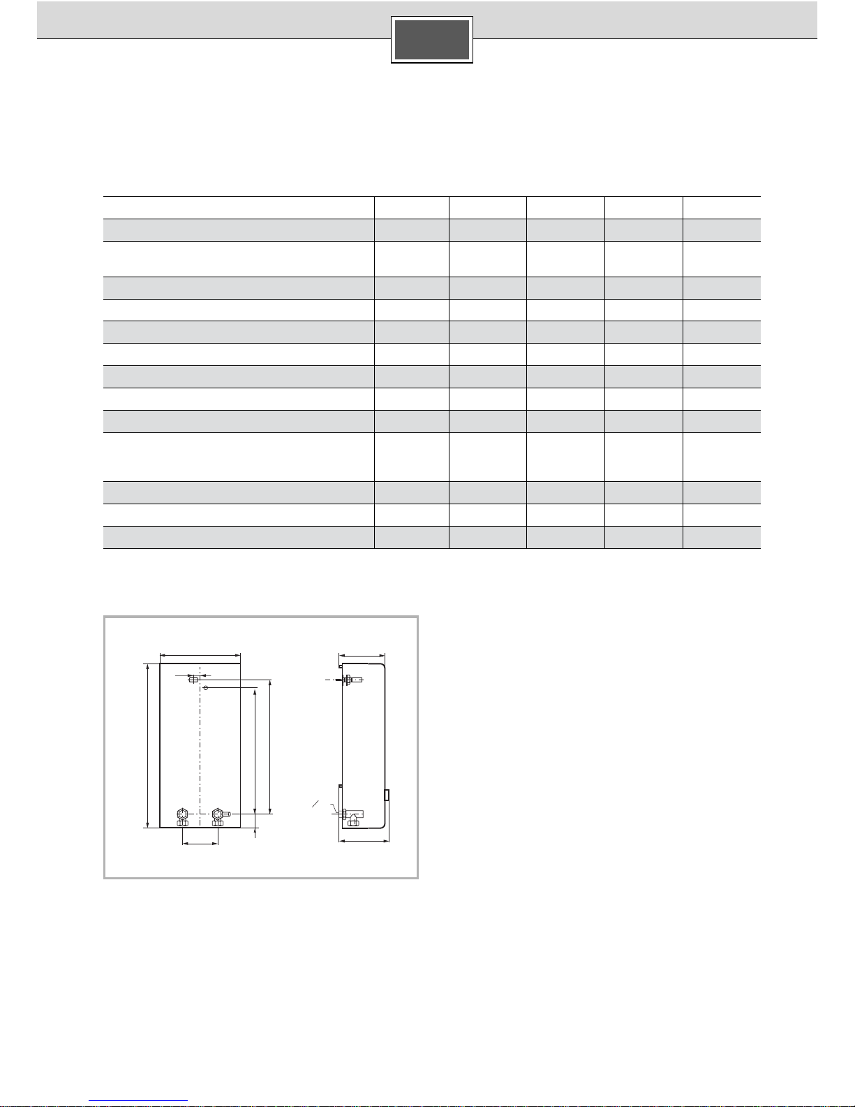
Technische Daten
* Hierzu kommt noch der Druckabfall an der Mischbatterie
Sonderzubehör
■ Rohrbausatz DLE 02RBS: Zur Verwendung des
Durchlauferhitzers als Untertischgerät.
■ Vorrangschalter (Lastabwurfrelais):
Für den Betrieb mit Vorrangschaltung.
■ Montageset DLE 02AP: Für Aufputzinstallation.
Nennleistung [kW] 18 21 24 27
Nennspannung 380 – 415V
380 – 415V 380 – 415V 400 V3~
Warmwassermenge bei Nennleistung
bei Temperaturerhöhung von
12 °C auf 38 °C [l/min] 9,9 11,6 13,2 13,9
12 °C auf 60 °C [l/min] 5,4 6,3 7,2 7,6
Einschaltmenge [l/min] 2,6 2,6 2,6 2,6
Einschaltfließdruck* [MPa (bar)] 0,025 (0,25) 0,025 (0,25) 0,025 (0,25) 0,025 (0,25)
Fließdruck (bei Nennleistung und 60 °C)*
mit Durchflussbegrenzer [MPa (bar)] 0,028 (0,28) 0,035 (0,35) 0,048 (0,48) 0,064 (0,64)
ohne Durchflussbegrenzer [MPa (bar)] 0,013 (0,13) 0,020 (0,20) 0,026 (0,26) 0,035 (0,35)
Einsatzbereich in Wässern
Spezifischer elektrischer Widerstand
bei 15 °C
[Ωcm] ≥ 1300 ≥ 1300 ≥ 1300 ≥ 1300
Nenndruck [MPa (bar)]
1 (10) 1 (10) 1 (10) 1 (10)
Maximal zulässige Zulauf-Temperatur [°C] 35 35 35 35
Maximale Netzimpedanz am Anschlussort [ Ω]
–
≤ 0,44
≤ 0,36
≤ 0,33
G
1
2
A
472
142
151
236
20
100
33242388
DE
3
Page 4
4
Assemble the instantaneous water heater as shown in
the illustrations. Observe the information in the text.
Safety information
■ The instantaneous water heater must only be
connected and started up by an authorised technician.
■ The statutory regulations of the respective country, as well
as those of the local electricity and water suppliers must
be adhered to.
■ The instantaneous water heater is an appliance of protec-
tion class I and must be connected to the protective earth
conductor.
■ The unit have to be connected durably to the mains
electricity supply via an all pole disconnecting device with
contact gap must be at least 3 mm.
■ The instantaneous water heater is suitable for enclosed
(pressurised) operation only.
■ The tap fittings must be permitted for operation with
enclosed (pressurised) instantaneous water heaters.
■ The instantaneous water heater must only be connected
to a cold-water pipe.
■ The instantaneous water heater is suitable for connection
to DVGW-tested plastic pipes.
■ The instantaneous water heater must only be installed
in a frost-free room.
■ Prior to installation, the electric connecting cable
must be disconnected from the mains voltage and
the water supply cut off!
■ Only connect the electric supply after the water
supply.
■ When making holes in the rear panel, only make the
number of holes required for installation. If the appliance
is reinstalled, any holes that are not used must be made
watertight.
■ Live components must not be touched subsequent to
installation.
Assembly
Unpacking/removing the
housing cover
■
Unpack the appliance and check for transportation
damage.
■ Dispose of the packaging and, where applicable, the old
appliance, in an environmentally conscious manner.
Preparation for assembly
Wall-mounted assembly
■
The instantaneous water heater must be fitted securely to
the wall. If required, secure the appliance using the lower
adjusting screws.
■ The distance from the wall is variable. This allows you to
compensate for any unevenness in the wall surface.
■ The sleeve in the rear panel must fit tightly round the
connection cable. If the sleeve is damaged during
installation, the holes must be sealed water-tight.
Water supply
■
The flow-through heater must be vented. Open the
warm water tap completely and allow to flow through
for one minute.
Electric supply
■
The mains connection terminal can either be mounted
above or below. At least 40 mm of the connecting cord’s
insulating jacket must be clamped inside the appliance.
Startup
■
For low water line pressure, remove the flow limiter (see
Supplementary Information A).
■ Instruct the user with regard to the operation of the
instantaneous water heater.
■ Separate the required language version from the rest of
the operating instructions. This can be kept in the swingout control panel of the instantaneous water heater.
Additional information
If the flow-through heater does not achieve adequate
flow as a result of water line pressure that is too low
in your house installation, remove the flow limiter.
Priority circuit for the combination with electrostorage heating units:
For operation with the priority circuit, a special load
reducing relay (special accessory) is required. Other
already existing load reducing relays with the exception of electronic load reducing relays could cause
malfunctions.
Status Indicator in the Heater
I.
LED Heater Status
Off Off
On Ready
Slow blinking (1/s) Heating
Fast blinking (4/s) The set temperatures are
not reached (the water flow
rate is too high for the
connection rating)
II.
III.
IV.
V.
VI.
A
B
C
GB
Page 5
5
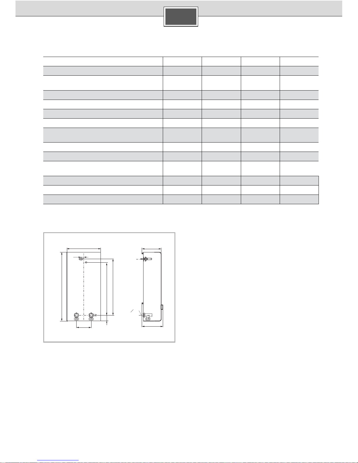
Specifications
* Plus any pressure loss at the tap mixer
Special accessories
■ DLE 02RBS Pipe set: When using the instantaneous
water heater as a built-under appliance.
■ Priority switch (load reducing relay):
For operation with the priority circuit.
■ DLE 02AP Mounting set: For surface-mount installation.
Rated power [kW] 18 21 24
Rated voltage 380 – 415V
380 – 415V 380 – 415V
Warm Water Quantity at Rated Power
for temperature increases of:
12 °C to 38 °C [l/min] 9.9 11.6 13.2
12 °C to 60 °C [l/min] 5.4 6.3 7.2
Switch-on quantity
[l/min] 2.6 2.6 2.6
Switch-on flow pressure* [MPa (bar)] 0.025 (0.25) 0.025 (0.25) 0.025 (0.25)
Flow pressure
(at rated power and 60 °C)*
With flow limiter [MPa (bar)] 0.028 (0.28) 0.035 (0.35) 0.048 (0.48)
Without flow limiter [MPa (bar)] 0.013 (0,13) 0.020 (0,20) 0.026 (0,26)
Operative range in waters of
specific electric resistance at 15 °C
[Ωcm] ≥ 1300 ≥ 1300 ≥ 1300
Rated pressure [MPa (bar)] 1 (10) 1 (10) 1 (10)
Maximum permissible supply temperature [°C] 35 35 35
Maximum mains impedance at connection site [Ω] – ≤ 0.44 ≤ 0.36
G
1
2
A
472
142
151
236
20
100
33242388
GB
Page 6
6
Montez le chauffe-eau instantané en suivant les
indications portées sur les figures. Respectez les
consignes du texte.
Consignes de sécurité
■ Seul un installateur agréé est autorisé à raccorder et
à mettre en marche le chauffe-eau instantané.
■ Respectez les prescriptions légales en vigueur dans
votre pays ainsi que celles édictées par les compagnies
locales/nationales distributrices d’électricité et d’eau et
applicables dans votre localité.
■ Le chauffe-eau instantané est un appareil qui répond à la
classe de protection I. Il doit être raccordé au fil de terre.
■ L’appareil doit être raccordé de manière durable et non
provisoire à une tuyauterie fixe.
■ Afin de respecter les prescriptions de sécurité
applicables, l’installation doit comporter un dispositif de
coupure tous pôles. L’espace coupe-circuit entre les
contacts doit s’élever à 3 mm minimum.
■ Le chauffe-eau est conçu uniquement pour fonctionner
en circuit fermé (résistant à la pression).
■ La robinetterie doit pouvoir s’utiliser avec des chauffe-
eau fermés (résistant à la pression).
■ Raccordez le chauffe-eau uniquement à une conduite
d’eau froide.
■ Le chauffe-eau peut s’utiliser avec de la tuyauterie en
matière plastique approuvée DVGW.
■ Installez le chauffe-eau uniquement dans un local non
exposé au gel.
■ Avant le montage, mettez le câble d’alimentation
électrique hors tension et coupez l’arrivée d’eau.
■ Procédez d’abord au raccordement de l’eau, puis au
raccordement électrique.
■ Pratiquez dans la paroi arrière uniquement les
ouvertures nécessaires au montage. Si vous refaites le
montage, bouchez les ouvertures inutilisées afin de les
rendre étanches.
■ Une fois le montage terminé, les pièces
électroconductrices doivent être impossibles à toucher.
Montage
Déballage/Enlèvement du
capot
■ Déballez l’appareil et vérifiez s’il n’a pas subi de dégâts
pendant le transport.
■ Eliminez l’emballage et, le cas échéant, l’ancien appareil
en respectant l’environnement.
Préparation du montage
Montage mural
■ Le chauffe-eau instantané doit être solidement monté
contre le mur. Le cas échéant, fixez-le au moyen des vis
de réglage inférieures.
■ L’écart par rapport au mur est variable. Vous pouvez
ainsi compenser les inégalités du mur.
■ La gaine doit bien enserrer le cordon d’alimentation.
Si elle a été endommagée pendant le montage, bouchez
les trous pour les rendre étanches à l’eau.
Raccordement de l’eau
■ Le chauffe-eau doit être purgé. Pour ce faire, ouvrir
complètement le robinet d’eau chaude et laisser l’eau
s’écouler pendant une minute.
Branchement électrique
■ La borne de branchement au secteur peut être montée en
haut ou en bas. La gaine du câble d’alimentation doit
pénétrer au moins de 40 mm dans l’appareil.
Mise en service
■ Retirer le limiteur de débit si la pression de la conduite
d’arrivée d’eau est faible (cf. la section « Information complémentaire et la fig. A »).
■ Expliquez à l’utilisateur le fonctionnement du chauffe-eau
instantané.
■ Sélectionnez dans la notice d’utilisation la version dans la
langue appropriée puis détachez-la. Vous pouvez la
ranger dans le bandeau de commande dépliant du
chauffe-eau instantané.
Informations supplémentaires
Si la pression de la conduite d’arrivée de l’eau de
votre installation est trop faible, le chauffe-eau peut
fournir un débit insuffisant. Pour augmenter le débit,
retirer alors le limiteur de débit.
Circuit de priorité pour l’association avec un radiateur
électrique à accumulation:
Pour travailler avec un circuit de priorité, il convient
d’installer un relais de délestage brusque spécial
(accessoire non fourni). Tout autre modèle de relais
de délestage brusque (à l’exception des modèles
électroniques) est susceptible de dysfonctionner.
Signification de la diode électroluminescente (DEL)
I.
DEL Appareil
éteinte arrêté
allumée prêt à fonctionner
clignotement lent (1/s) l’appareil chauffe
clignotement rapide
(4/s)
La température programmée
n’est pas atteinte (le débit d’eau
est trop élevé pour la puissance
électrique disponible)
II.
III.
IV.
V.
VI.
A
B
C
FR
Page 7

7
Données techniques
* Lui ajouter la perte de pression au mitigeur
Accessoires en option
■ Tuyauterie de montage en kit DLE 02RBS :
permet d’utiliser le chauffe-eau sous l’évier.
■ Commutateur de priorité (relais de décharge) :
Pour exploitation avec un circuit de priorité.
■ Kit de montage DLE 02AP : pour une installation sur crépi.
Puissance nominale [kW] 18 21 24
Tension nominale 380 – 415V 380 – 415V 380 – 415V
Débit d’eau fourni à la puissance nominale
pour une augmentation de température de
12 °C à 38 °C [l/min] 9,9 11,6 13,2
12 °C à 60 °C [l/min] 5,4 6,3 7,2
Débit de déclenchement [l/min] 2,6 2,6 2,6
Pression de déclenchement* [MPa (bar)] 0,025 (0,25) 0,025 (0,25) 0,025 (0,25)
Pression d’écoulement
(à puissance nominale et pour 60 °C)*
Avec limiteur de débit [MPa (bar)] 0,028 (0,28) 0,035 (0,35) 0,048 (0,48)
Sans limiteur de débit [MPa (bar)] 0,013 (0,13) 0,020 (0,20) 0,026 (0,26)
Rayon d’action dans l’eau
Résistance électrique spécifique à 15 °C
[Ωcm] ≥ 1300 ≥ 1300 ≥ 1300
Pression nominale [MPa (bar)] 1 (10) 1 (10) 1 (10)
Température maximale admissible à l’entrée [°C] 35 35 35
Impédance maximale du réseau sur les lieux [Ω] – ≤ 0,44 ≤ 0,36
G
1
2
A
472
142
151
236
20
100
33242388
FR
Page 8

8
Monteer het doorstroom heetwaterapparaat volgens de
afbeeldingen. Volg de instructies in de tekst op.
Veiligheidsvoorschriften
■ Het doorstroom heetwaterapparaat mag uitsluitend
door een installateur aangesloten en in gebruik
worden genomen.
■ De wettelijke voorschriften van het betreffende land, van
het plaatselijke energiebedrijf en van het
waterleidingbedrijf opvolgen.
■ Het doorstroom heetwaterapparaat is een apparaat van
beschermklasse I en moet worden aangesloten op een
aardleiding.
■ Het toestel moet duurzaam op vast geïnstalleerde
leidingen worden aangesloten.
■ Om te voldoen aan de geldende veiligheidsvoorschriften
moet de installatie zijn voorzien van een stroomonderbreker voor alle polen. De contactopening moet minimaal
3 mm bedragen.
■ Het apparaat is uitsluitend geschikt voor gesloten
(drukvast) gebruik.
■ Armaturen moeten goedgekeurd zijn voor gebruik met
gesloten (drukvaste) doorstroom heetwaterapparaten.
■ Het doorstroom heetwaterapparaat uitsluitend aansluiten
op een koudwaterleiding.
■ Het doorstroom heetwaterapparaat is geschikt voor
aansluiting op goedgekeurde kunststof buizen.
■ Het doorstroom heetwaterapparaat uitsluitend
installeren in een vorstvrije ruimte.
■ De elektrische aansluitkabel voor de montage
spanningsloos maken en de wateraanvoer afsluiten!
■ De elektrische aansluiting pas uitvoeren nadat het
water is aangesloten.
■ Maak in de achterzijde uitsluitend gaten die nodig zijn
voor de montage. Als het apparaat opnieuw wordt
gemonteerd, moeten de ongebruikte gaten waterdicht
worden afgesloten.
■ Onder spanning staande onderdelen mogen na de
montage niet meer aangeraakt kunnen worden.
Montage
Uitpakken/kap verwijderen
■ Het apparaat uitpakken en controleren op transport-
schade.
■ De verpakking en eventueel het oude apparaat op
milieuvriendelijke wijze afvoeren.
Montagevoorbereiding
Montage op de muur
■ Het doorstroom heetwaterapparaat moet vast op de
muur worden gemonteerd. Bevestig het apparaat
eventueel aan de onderste stelschroeven.
■ De afstand tot de muur is variabel. Zo kunnen
oneffenheden van de muur worden gecompenseerd.
■ De tule moet de aansluitkabel nauw omsluiten. Als de
tule beschadigd raakt tijdens de montage, moeten de
gaten waterdicht worden afgesloten.
Wateraansluiting
■ Het doorstroomtoestel moet worden ontlucht.
Open daarvoor de warmwaterkraan helemaal en spoel
het toestel gedurende één minuut door.
Elektro-aansluiting
■ De netaansluitklem kan boven of beneden gemonteerd
worden. De mantel van de aansluitkabel moet minstens
40 mm in het toestel naar binnen steken.
Ingebruikneming
■ Verwijder bij een lage waterleidingdruk de doorstroom-
begrenzer (zie aanvullende informatie A).
■ Leg de gebruiker uit hoe het doorstroom
heetwaterapparaat wordt bediend.
■ Haal de gewenste taalversie uit de gebruiksaanwijzing.
U kunt deze bewaren in het uitklapbare bedieningspaneel
van het doorstroom heetwaterapparaat.
Aanvullende informatie
Wanneer het doorstroomtoestel wegens te geringe
waterdruk in uw huisinstallatie geen voldoende
doorstroming krijgt, moet u de doorstroombegrenzer
verwijderen.
Voorrangschakeling voor de combinatie met elektrische reservoirverwarmingsapparaten:
Voor het gebruik met voorrangschakeling is een
speciaal lastafwerprelais (speciaal toebehoren)
vereist. Andere, reeds aanwezige lastafwerprelais,
met uitzondering van elektronische lastafwerprelais,
kunnen gebrekkig functioneren.
Statusaanduiding in het apparaat
I.
LED Apparaatstatus
Uit Uit
Aan Standby
Langzaam knipperen (1/s) Apparaat verwarmt
Snel knipperen (4/s) Ingestelde temperatuur
wordt niet bereikt
(waterdoorvoer voor de
aansluitcapaciteit te groot)
II.
III.
IV.
V.
VI.AB
C
NL
Page 9

9
Technische gegevens
* Dit is exclusief de drukvermindering bij de mengkraan
Speciaal toebehoren
■ Buizenmontageset DLE 02RBS: voor gebruik van het
doorstroom heetwaterapparaat als keukenboiler.
■ Voorrangschakelaar (lastafwerprelais):
Voor het gebruik met voorrangschakeling.
■ Montageset DLE 02AP: Voor opbouwmontage.
Nominaal vermogen [kW] 18 21 24
Nominale spanning 380 – 415 V 380 – 415V 380 – 415V
Warmwaterhoeveelheid bij nominale capaciteit
bij temperatuurverhoging van
12 °C naar 38 °C [l/min] 9,9 11,6 13,2
12 °C naar 60 °C [l/min] 5,4 6,3 7,2
Inschakelhoeveelheid [l/min] 2,6 2,6 2,6
Inschakelstroomduk* [MPa (bar)] 0,025 (0,25) 0,025 (0,25) 0,025 (0,25)
Stroomdruk
(bij nominale capaciteit en 60 °C)*
met doorstroombegrenzer [MPa (bar)] 0,028 (0,28) 0,035 (0,35) 0,048 (0,48)
zonder doorstroombegrenzer [MPa (bar)] 0,013 (0,13) 0,020 (0,20) 0,026 (0,26)
Toepassingsbereik bij water
met een specifieke elektrische weerstand op 15 °C
[Ωcm] ≥ 1300 ≥ 1300 ≥ 1300
Nominale druk [MPa (bar)] 1 (10) 1 (10) 1 (10)
Maximaal toegestane toevoertemperatuur [°C] 35 35 35
Maximale netimpedantie op de aansluitlocatie [Ω] – ≤ 0,44 ≤ 0,36
G
1
2
A
472
142
151
236
20
100
33242388
NL
Page 10

10
Monte el calentador de paso continuo tal como se
describe en las imágenes. Observe las indicaciones que
se dan en el texto.
Indicaciones de
seguridad
■ El calentador de paso continuo tiene que ser instalado
y puesto en funcionamiento por un técnico
especialista.
■ Hay que observar las disposiciones legales del país
correspondiente y de las compañías abastecedoras de
electricidad y de agua locales.
■ El calentador de paso continuo es un aparato de la clase
de protección I y es obligatorio conectarlo a un conductor de puesta a tierra.
■ El aparato tiene que estar conectado de forma perma-
nente a tuberías fijas.
■ Al objeto de cumplir con las disposiciones de seguridad
pertinentes, la instalación debe llevar un dispositivo de
separación omnipolar. La abertura de contactos tiene que
tener 3 mm como mínimo.
■ El calentador de paso continuo sólo está indicado para
operar en circuito cerrado (resistente a la presión).
■ La grifería debe estar homologada para el funcionamiento
con calentadores de paso continuo de circuito cerrado
(resistente a la presión).
■ El calentador de paso continuo ha de conectarse
únicamente a una tubería de agua fría.
■ El calentador de paso continuo puede conectarse a
tuberías de plástico verificadas por la Asociación alemana
de instaladores de gas y agua (DVGW).
■ Instalar el calentador de paso continuo sólo en
recintos protegidos contra las heladas.
■ ¡Antes del montaje hay que dejar sin corriente el cable
de conexión eléctrica y cerrar el paso del agua!
■ Conectar la corriente sólo después de haber
conectado el agua.
■ Perforar en la pared trasera sólo los orificios necesarios
para la instalación. Si hay que realizar una nueva
instalación, hay que tapar los orificios no empleados
dejándolos impermeables.
■ Después de la instalación no debe ser posible tocar los
elementos que conducen electricidad.
Montaje
Desembalar/Quitar
recubrimiento
■ Desembalar el aparato y controlar que no haya daños
producidos por el transporte.
■ Eliminar el embalaje y, dado el caso, el aparato viejo
teniendo en cuenta la protección el medio ambiente.
Preparativos para la instalación
Instalación mural
■ El calentador de paso continuo ha de montarse de modo
que quede perfectamente fijo en la pared. Dado el caso,
fíjelo en los tornillos de ajuste inferiores.
■ La distancia con respecto a la pared es variable. De esta
forma es posible compensar irregularidades en la superficie de la pared.
■ El manguito debe envolver bien y estrechamente el cable
de conexión. Si resultara dañado durante la instalación,
los agujeros deben taparse y quedar impermeables.
Toma de agua
■ Hay que purgar el aire del calentador de paso conti-
nuo. Para ello hay que abrir al máximo el grifo del agua
caliente y dejar que ésta fluya a través del aparato
durante 1 minuto.
Conexión eléctrica
■ El borne de conexión a la red puede montarse arriba o
abajo. El revestimiento del cable de conexión tiene que
entrar en el aparato 40 mm como mínimo.
Puesta en servicio
■ Si hubiera una presión baja en la tubería del agua, hay que
retirar el limitador de caudal (véase información adicional A).
■ Explique al usuario cómo manejar el calentador de paso
continuo.
■ Separe de las instrucciones de uso la parte correspon-
diente al idioma requerido. Ésta se puede guardar en el
panel de mandos abatible del calentador de paso continuo.
Informaciones adicionales
Si el calentador de paso continuo no alcanzara un
caudal suficiente debido a que la presión de la tubería
de agua en la instalación doméstica es demasiado
baja, retire el limitador de caudal.
Conmutador de prioridad para la combinación con
radiadores termoeléctricos de acumulación:
Para el funcionamiento con conmutación de prioridad
se requiere un relé de desconexión de carga especial
(accesorio especial). Otros relés de desconexión de
cargas que estuvieran ya presentes, a excepción de
los electrónicos, pueden dar lugar a disfunciones.
Indicación de estado en el aparato
I.
LED Estado del aparato
Apagado Desconectado
Encendido Disponibilidad
Parpadeo lento (1/s) El aparato calienta
Parpadeo rápido (4/s) No se alcanza la temperatura
ajustada (el caudal de agua
es demasiado fuerte para la
potencia de conexión)
II.
III.
IV.
V.
VI.
A
B
C
ES
Page 11

11
Datos técnicos
* Aquí hay que añadir aún la caída de presión en la batería de mezcla
Accesorios especiales
■ Juego de tuberías DLE 02RBS: Para montar el calentador
de paso continuo debajo de un mueble.
■ Conmutador de prioridad (relé de desconexión de cargas):
Para el funcionamiento con conmutación de prioridad.
■ Juego de montaje DLE 02AP: Para la instalación sobre
revoque.
Potencia nominal [kW] 18 21 24
Tensión nominal 380 – 415V 380 – 415 V 380 – 415V
Cantidad de agua caliente con potencia nominal
con aumento de temperatura de
12 °C a 38 °C [l/min] 9,9 11,6 13,2
12 °C a 60 °C [l/min] 5,4 6,3 7,2
Caudal de puesta en marcha [l/min] 2,6 2,6 2,6
Presión de caudal de puesta en marcha* [MPa (bar)] 0,025 (0,25) 0,025 (0,25) 0,025 (0,25)
Presión de caudal
(con potencia nominal y 60 °C)*
con limitador de caudal [MPa (bar)] 0,028 (0,28) 0,035 (0,35) 0,048 (0,48)
sin limitador de caudal [MPa (bar)] 0,013 (0,13) 0,020 (0,20) 0,026 (0,26)
Rango de aplicación en aguas
con resistencia eléctrica específica a 15 °C
[Ωcm] ≥ 1300 ≥ 1300 ≥ 1300
Presión nominal [MPa (bar)] 1 (10) 1 (10) 1 (10)
Temperatura de entrada máxima permitida [°C] 35 35 35
Impedancia de red máxima en el lugar de conexión [Ω] – ≤ 0,44 ≤ 0,36
G
1
2
A
472
142
151
236
20
100
33242388
ES
Page 12

12
Podgrzewacz przep∏ywowy zamontowaç tak, jak to
opisano w cz´Êci z rysunkami. Przestrzegaç wskazówek
podanych w tekÊcie.
Wskazówki bezpieczeƒstwa
■ Przy∏àczenia i pierwszego uruchomienia
podgrzewacza przep∏ywowego mo˝e dokonaç tylko
uprawniony specjalista.
■ Przestrzegaç obowiàzujàcych przepisów krajowych,
przepisów miejscowych zak∏adów energetycznych i
wodociàgowych.
■ Podgrzewacz przep∏ywowy jest urzàdzeniem klasy
bezpieczeƒstwa I i musi byç pod∏àczone do przewodu
uziemiajàcego.
■ Urzàdzenie musi byç na sta∏e zamontowane do sieci
wodno-kanalizacyjnej.
■ W celu spe∏nienia warunków obowiàzujàcych przepisów
bezpieczeƒstwa nale˝y wyposa˝yç instalacj´ elektrycznà
w wy∏àcznik wszystkich faz. Rozwarcie styków wy∏àcznika
musi wynosiç co najmniej 3 mm.
■ Podgrzewacz przep∏ywowy przeznaczony jest tylko do
pracy zamkni´tej (sta∏e ciÊnienie).
■ Zastosowaç armatur´, która dopuszczona jest do pracy
zamkni´tej (sta∏e ciÊnienie).
■ Podgrzewacz przep∏ywowy pod∏àczaç tylko do przewodu
zimnej wody.
■ Podgrzewacz przep∏ywowy nadaje si´ do przy∏àczenia do
przewodów rurowych z tworzywa sztucznego, które
posiadajà certyfikat DVGW.
■ Podgrzewacz przep∏ywowy musi byç zainstalowany w
pomieszczeniu chroniàcym przed mrozem.
■ Przed przystàpieniem do monta˝u wy∏àczyç przewód
elektryczny spod napi´cia i zamknàç wodny zawór
odcinajàcy!
■ Przy∏àcza wodne wykonaç przed pod∏àczeniem
urzàdzenia do sieci elektrycznej.
■ W tylnej Êciance wy∏amaç tylko te otwory, które konieczne
sà do monta˝u. W przypadku ponownego monta˝u nale˝y
zb´dne otwory zaÊlepiç wodoszczelnie.
■ Cz´Êci przewodzàce pràd nie mogà byç dost´pne po
monta˝u.
Monta˝
Rozpakowanie/zdejmowanie
pokrywy
■ Urzàdzenie rozpakowaç i sprawdziç, czy nie posiada
uszkodzeƒ powsta∏ych w czasie transportu.
■ Opakowanie i stare urzàdzenie usunàç w sposób zgodny
z przepisami o ochronie Êrodowiska.
Przygotowanie do monta˝u
Monta˝ na Êcianie
■ Podgrzewacz przep∏ywowy musi byç zamontowany na
sta∏e na Êcianie. W takim przypadku zamocowaç go na
dolnych Êrubach mocujàcych.
■ Odleg∏oÊç od Êciany jest ró˝na. W taki sposób mo˝na
wyrównaç nierównoÊci Êciany.
■ Tulejka ochronna musi ciasno obejmowaç przewód
elektryczny. W przypadku uszkodzenia tulejki przy
monta˝u, nale˝y zaÊlepiç otwory wodoszczelnie.
Przy∏àcze wodne
■ Przep∏ywowy ogrzewacz wody musi byç odpowietrzony.
Kran ciep∏ej wody ca∏kowicie odkr´ciç i przez 1 minut´
urzàdzenie p∏ukaç.
Przy∏àcze elektryczne
■ Przy∏àczeniowy zacisk sieciowy mo˝e byç zamontowany
na górze lub na dole. Izolacja zewn´trzna (p∏aszcz) kabla
przy∏àczeniowego musi si´gaç przynajmniej na 40 mm
wg∏àb urzàdzenia.
Uruchomienie
■ Przy niskim ciÊnieniu wody usunàç ogranicznik przep∏ywu
(patrz tak˝e informacja dodatkowa A).
■ Prosz´ wyjaÊniç u˝ytkownikowi obs∏ug´ podgrzewacza
przep∏ywowego.
■ Z instrukcji u˝ytkowania wybraç w∏aÊciwà wersj´
j´zykowà. Mo˝na jà przechowywaç w odchylanym pulpicie
obs∏ugi podgrzewacza.
Informacje dodatkowe
JeÊli na skutek zbyt niskiego ciÊnienia wody w
instalacji domowej ogrzewacz nie osiàgnie
odpowiedniego przep∏ywu, usunàç ogranicznik
przep∏ywu.
Za∏àczanie wst´pne kombinacji elektrycznych piecy
akumulacyjnych:
do pracy z za∏àczaniem wst´pnym niezb´dny jest
specjalny przekaênik przecià˝eniowy (wyposa˝enie
dodatkowe). Inne, aktualnie u˝ywane, z wy∏àczeniem
elektronicznych przekaêników przecià˝eniowych,
mogà pracowaç nieprawid∏owo.
Wskazania stanu urzàdzenia
■
I.
Dioda LED Stan urzàdzenia
Wy∏àczone Wy∏àczone
W∏àczone Stan gotowoÊci
B∏yska powoli (1/s) Urzàdzenie grzeje
B∏yska szybko (4/s) Nastawiona temperatura nie
zostanie osiàgni´ta
(zbyt du˝y przep∏yw wody dla
przepustowoÊci przy∏àcza)
II.
III.
IV.
V.
VI.AB
C
PL
Page 13

13
Dane techniczne
* Tutaj nale˝y uwzgl´dniç dodatkowo spadek ciÊnienia na baterii mieszajàcej
Wyposa˝enie dodatkowe
■ Zestaw kszta∏tek i z∏àczek rurowych DLE 02RBS:
do zamontowania podgrzewacza przep∏ywowego pod
umywalkà.
■ W∏àcznik wst´pny (przekaênik obcià˝eniowy):
do pracy z zabezpieczeniem przecià˝eniowym.
■ Zestaw monta˝owy DLE 02AP: dla instalacji natynkowej.
Moc znamionowa [kW] 18 21 24
Napi´cie znamionowe 380 – 415V 380 – 415 V 380 – 415V
IloÊç ciep∏ej wody przy wydajnoÊci znamionowej,
przy podniesieniu temperatury z:
12 °C na 38 °C [l/min] 9,9 11,6 13,2
12 °C na 60 °C [l/min] 5,4 6,3 7,2
IloÊç za∏àczajàca [l/min] 2,6 2,6 2,6
CiÊnienie hydrauliczne za∏àczenia * [MPa (bary)] 0,025 (0,25) 0,025 (0,25) 0,025 (0,25)
CiÊnienie hydrauliczne
(przy wydajnoÊci nominalnej i 60°C) *
z ogranicznikiem przep∏ywu [MPa (bary)] 0,028 (0,28) 0,035 (0,35) 0,048 (0,48)
bez ogranicznika przep∏ywu [MPa (bary)] 0,013 (0,13) 0,020 (0,20) 0,026 (0,26)
Zakres stosowania dla wody o
opornoÊci elektrycznej w∏aÊciwej
w temperaturze 15 °C
[Ωcm] ≥ 1300 ≥ 1300 ≥ 1300
CiÊnienie znamionowe [MPa (bary)] 1 (10) 1 (10) 1 (10)
Maksymalna dopuszczalna temperatura dop∏ywu [°C] 35 35 35
Maksymalna impedancja sieciowa
w miejscu przy∏àczenia
[Ω] – ≤ 0,44 ≤ 0,36
G
1
2
A
472
142
151
236
20
100
33242388
PL
Page 14

Page 15

Dimplex
Garantieurkunde für Hauswärmetechnik
(Speicherheizgeräte, dezentrale Wohnungslüftung, Kaminfeuer,
Direktheizgeräte, Industrieheizgeräte, Luftschleier, Händetrockner,
Fußbodenheizmatten, Heizbänder, Warmwassergeräte, Klimageräte)
gültig für Deutschland und Österreich
(Ausgabestand 04/2004)
Die nachstehenden Bedingungen, die Voraussetzungen und Umfang unserer Garantieleistung umschreiben, lassen die Gewährleistungsverpflichtungen des Verkäufers aus dem Kaufvertrag mit dem Endabnehmer unberührt. Für die Geräte leisten wir
Garantie gemäß nachstehenden Bedingungen:
Wir beheben unentgeltlich nach Maßgabe der folgenden Bedingungen Mängel am Gerät, die nachweislich auf einem Materialund/oder Herstellungsfehler beruhen, wenn sie uns unverzüglich nach Feststellung und innerhalb von 24 Monaten nach Lieferung an den Erstendabnehmer gemeldet werden. Bei gewerblichem Gebrauch innerhalb von 12 Monaten. Zeigt sich der Mangel innerhalb von 6 Monaten ab Lieferung, wird vermutet, dass es sich um einen Material- oder Herstellungsfehler handelt.
Dieses Gerät fällt nur dann unter diese Garantie, wenn es von einem Unternehmer in einem der Mitgliedstaaten der Europäischen Union gekauft wurde, es bei Auftreten des Mangels in Deutschland oder Österreich betrieben wird und Garantieleistungen auch in Deutschland oder Österreich erbracht werden können.
Die Behebung der von uns als garantiepflichtig anerkannter Mängel geschieht dadurch, dass die mangelhaften Teile unentgeltlich nach unserer Wahl instandgesetzt oder durch einwandfreie Teile ersetzt werden. Durch Art oder Ort des Einsatzes des Gerätes bedingte außergewöhnliche Kosten der Mängelbeseitigung werden nicht übernommen. Ausgebaute Teile, die wir
zurücknehmen, gehen in unser Eigentum über. Die Garantiezeit für Nachbesserungen und Ersatzteile endet mit dem Ablauf der
ursprünglichen Garantiezeit für das Gerät. Die Garantie erstreckt sich nicht auf leicht zerbrechliche Teile, die den Wert oder die
Gebrauchstauglichkeit des Gerätes nur unwesentlich beeinträchtigen. Es ist jeweils der Original-Kaufbeleg mit Kauf- und/oder
Lieferdatum vorzulegen.
Zur Erlangung der Garantie für Fußbodenheizmatten, ist das den Projektierungsunterlagen oder das in der Montageanweisung
enthaltene Prüfprotokoll ausgefüllt innerhalb vier Wochen, nach Einbau der Heizung, an unten stehende Adresse zu senden.
Eine Garantieleistung entfällt, wenn vom Endabnehmer oder einem Dritten die entsprechenden VDE-Vorschriften, die Bestimmungen der örtlichen Versorgungsunternehmen oder unsere Montage- und Gebrauchsanweisung nicht beachtet worden sind.
Durch etwa seitens des Endabnehmers oder Dritter unsachgemäß vorgenommenen Änderungen und Arbeiten, wird die Haftung für die daraus entstehenden Folgen aufgehoben. Die Garantie erstreckt sich auf vom Lieferer bezogene Teile. Nicht vom
Lieferer bezogene Teile und Geräte-/Anlagenmängel die auf nicht vom Lieferer bezogene Teile zurückzuführen sind fallen nicht
unter den Garantieanspruch.
Sofern der Mangel nicht beseitigt werden kann, oder die Nachbesserung von uns abgelehnt oder unzumutbar verzögert wird,
wird der Hersteller entweder kostenfreien Ersatz liefern oder den Minderwert vergüten. Im Falle einer Ersatzlieferung, behalten
wir uns die Geltendmachung einer angemessenen Nutzunganrechnung, für die bisherigen Nutzungszeit, vor. Weitergehende
oder andere Ansprüche, insbesondere solche auf Ersatz außerhalb des Gerätes entstandener Schäden sind soweit eine Haftung nicht zwingend gesetzlich angeordnet ist ausgeschlossen.
Im Kundendienstfalle ist die Robert Bosch Hausgeräte GmbH als zuständiger Kundendienst zu informieren.
Weiterverlinkung auf Explosionszeichnungen und online-Ersatzteile-Bestellungen (nur in Deutschland möglich) bei der Robert
Bosch Hausgeräte GmbH im Internet unter: http:
//www.dimplex.de/quickfinder
Für die Auftragsbearbeitung werden die Erzeugnisnummer E-Nr. und das Fertigungsdatum FD des Gerätes benötigt. Diese
Angaben befinden sich auf dem Typschild, in dem stark umrandeten Feld.
Bereitschaftsdienst in Notfällen auch an Wochenenden und Feiertagen!
KKW Kulmbacher Klimageräte-Werk GmbH, Geschäftsbereich Dimplex, Abt.: VHP, Am Goldenen Feld 18, D-95326 Kulmbach,
Tel.-Nr. +49 (0) 9221/709-564, Fax-Nr. +49 (0) 9221/709-565
E-Mail-Adresse: kundendienst.hauswaerme@kkw.de
kundendienst.hauswaerme@dimplex.de
Internet: www.kkw.de www.dimplex.de
Auftragsannahme Deutschland
Tel.-Nr. 01801/22 33 55 *)
Fax-Nr. 01801/33 53 07 *)
Ersatzteile-Bestellungen Deutschland
Tel.-Nr. 01801/33 53 04
Fax-Nr. 01801/33 53 08
E-Mail: spareparts@bshg.com
*) gültig für Deutschland
Die Robert Bosch Hausgeräte-GmbH ist an 7 Tagen, 24 Stunden für Sie persönlich erreichbar! (Gilt nur in Deutschland.)
Auftragsannahme Österreich
Tel.-Nr. 0810/240 260 **)
Fax-Nr. (01) 60575-51212 **)
E-Mail: hausgeraete.ad@bshg.com
Ersatzteile-Bestellungen Österreich
Tel.-Nr. 0810/240 261 **)
Fax.-Nr (01) 60575-51212 **)
E-Mail: hausgeraete.et@bshg.com
**) gültig für Österreich
Internationales Teile-Logistikcenter in Fürth Tel.-Nr.: +49 (0) 911/93 04 68
Fax-Nr.: +49 (0) 911/9 30 42 44
Tel.-Nr.: +43 (1) 60575/4 91 52
Fax-Nr.:+43 (1) 60575/5 12 36
Page 16

CE-Konformitätserklärung
Dieses Gerät wurde in Übereinstimmung mit den EU-Richtlinien für Niederspannung (73/23/EWG) und elektromagnetische Verträglichkeit (89/336/EWG) entwickelt und gefertigt. 9 000 008 941
KKW Kulmbacher Klimageräte-Werk GmbH
Geschäftsbereich Dimplex
Am Goldenen Feld 18
95326 Kulmbach
www.dimplex.de
Telefon +49 (0) 9221/709-564
Telefax +49 (0) 9221/709-565
Technische Änderungen vorbehalten
Bestell-Nr.: 451505.66.19
Printed in Germany 06/04
Page 17

4.
4.
3.
I.
5.
1.
1.
2.
Page 18

II.
100
1.
2.
3.
4.
388
ca. 96
70
44
100
ca. 72
332
5.
Page 19

III.
max. 17 mm
max. 31 mm
ca. 2 mm
ca. 16 mm
3.
4.
2.
1.
Page 20

IV.
4.
2.
2.
3.
4.
6.
7.
5.1.
1 Minute entlüften!
Vent for one
minute!
Aérer pendant 1 minute !
1 minuut ontluchten!
¡Purgar durante
1 minuto!
Odpowietrzaç 1 minut´!
warm
hot
chaud
warm
caliente
ciep∏y
Page 21

V.
min. 40 mm
0 mm
1.
2.
RESET
L1
L2
L3
PE
L3
PE
L1
L2
min. 40 mm
6.
5.
3.
4.
Page 22

LED
L 3
L 2
L 1
3
2
1
PE
PE
2.
1.
3.
VI.
✂
A
B
C
5. 6.
7.
8.
3.
4.
1.
2.
 Loading...