

Service Manual
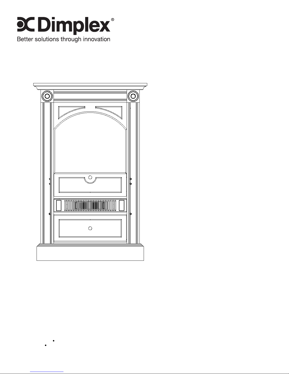
Chelsea Freestanding
Corner Fireplace
Model Number
DCF7850
EMSC
UL Part Number
6901820200
IMPORTANT SAFETY INFORMATION: Always read this manual rst before attempting to service this
replace. For your safety, always comply with all warnings and safety instructions contained in this
manual to prevent personal injury or property damage.
Dimplex North America Limited
1367 Industrial Road
1-888-346-7539 www.dimplex.com
In keeping with our policy of continuous product development, we reserve the right to make changes without notice.
© 2011 Dimplex North America Limited
Cambridge ON Canada N1R 7G8
REV PCN DATE
00 - 17-AUG-11
7400390000R00

TABLE OF CONTENTS
OPERATION .........................................................3
MAINTENANCE . . . . . . . . . . . . . . . . . . . . . . . . . . . . . . . . . . . . . . . . . . . . . . . . . . . . . . 4
EXPLODED PARTS DIAGRAM . . . . . . . . . . . . . . . . . . . . . . . . . . . . . . . . . . . . . . . . . . 5
WIRING DIAGRAM ....................................................6
PREPARATION FOR SERVICE . . . . . . . . . . . . . . . . . . . . . . . . . . . . . . . . . . . . . . . . . . 7
LIGHT HARNESS REPLACEMENT .......................................7
FLICKER MOTOR/FLICKER ROD REPLACEMENT ..........................8
HEATER ASSEMBLY REPLACEMENT ....................................9
SWITCH REPLACEMENT – (3-POSITION OR HEAT ON/OFF) .................9
THERMOSTAT REPLACEMENT . . . . . . . . . . . . . . . . . . . . . . . . . . . . . . . . . . . . . . . . 10
REMOTE CONTROL RECEIVER REPLACEMENT ..........................11
POWER CORD REPLACEMENT ........................................11
ASSEMBLY PART PICTURES ..........................................13
TROUBLESHOOTING GUIDE . . . . . . . . . . . . . . . . . . . . . . . . . . . . . . . . . . . . . . . . . . 16
Always use a qualied technician or service agency to repair this replace.
!
NOTE: Procedures and techniques that are considered important enough to emphasize.
CAUTION: Procedures and techniques which, if not carefully followed, will result in damage to the
equipment.
WARNING: Procedures and techniques which, if not carefully followed, will expose the user to the
risk of re, serious injury, or death.
2 www.dimplex.com
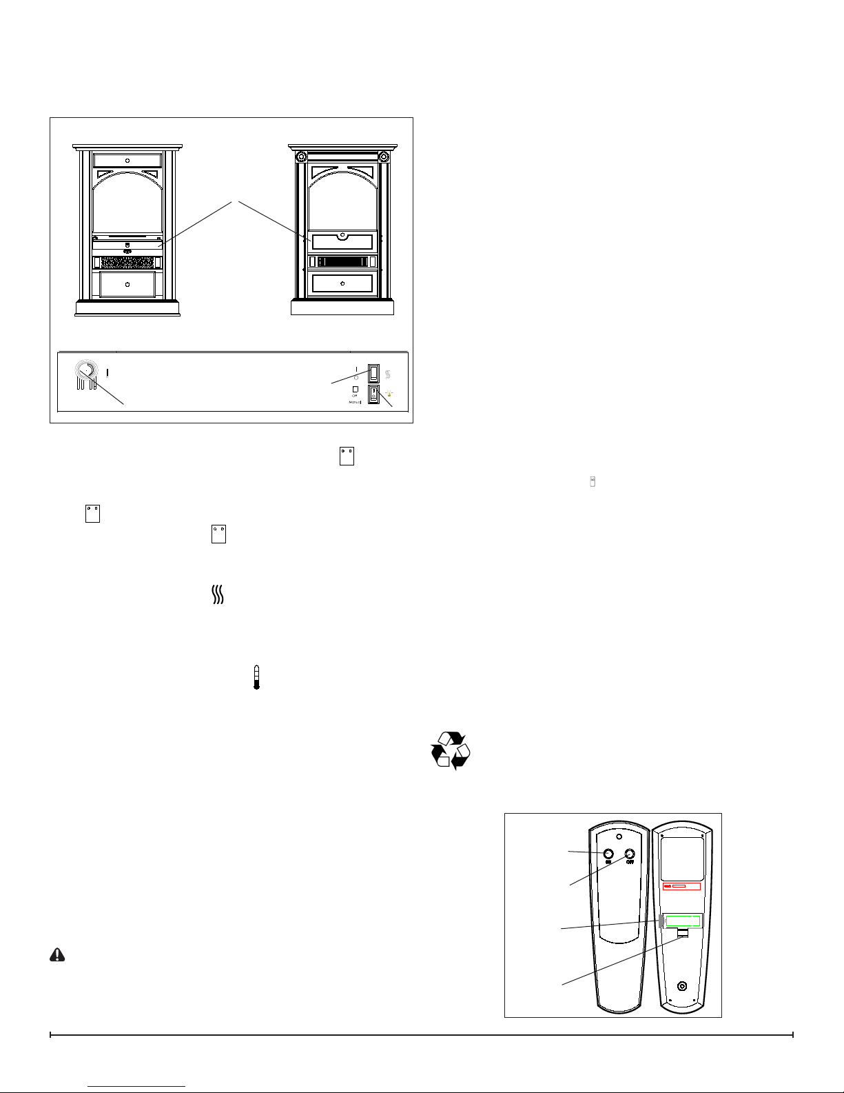
OPERATION
The controls are located inside the door panel on the lower
side of the Corner Standing Stove (Figure 1).
Figure 1
Door Panel
EMSC Models
DCF7850 Models
Remote Control
The replace is supplied with a radio frequency remote
control. This remote control has a range of approximately
50 feet (15.25 m), it does not have to be pointed at the
replace and can pass through most obstacles (including
walls). It is supplied with one of hundreds of independent
frequencies to prevent interference with other units.
!
NOTE: Before attempting any operation with the
remote, pull the plastic insulator strip out from between
the remote casing and battery cover (Figure 2).
Remote Operation
The replace is supplied with an integrated on/off remote
control.
!
NOTE: Ensure that the replace 3-Position Switch is set
to the remote control setting.
To operate, push the ON button to turn replace on, push
the OFF button to turn the replace off.
B
C
A. 3-Position Switch
The switch has two ON positions marked with “
Manual ”. The “ Manual ” position is for manual operation.
In this position the built-in remote control is bypassed.
The “
remote control. When in “
with the ON and OFF buttons of the remote control.
When the switch is in the center “ O ”position the unit is off.
B. Heater On/Off Switch
The Heater On/Off Switch supplies power to the heater
element. When the switch is in the ON position the heater
operates if the thermostat calls for heat.
C. Heater Thermostat Control
To adjust the temperature to your individual requirements,
turn the thermostat control clockwise all the way to
turn on the heater. When the room reaches the desired
temperature, turn the thermostat knob counter clockwise
until you hear a click. Leave in this position to maintain the
room temperature at this setting. For additional heat, turn
clockwise until you hear the click again and the heater will
turn on.
” position is for operating the unit with the provided
” position the unit is operated
A
” and “
Resetting The Temperature Cutoff Switch
Should the heater overheat, an automatic cut out will turn
the replace off and it will not come back on without being
reset. It can be reset by switching the 3-Position Switch to
OFF and waiting ve (5) minutes before switching the unit
back on.
CAUTION: If you need to continuously reset the heater,
disconnect power and call Dimplex customer service at
1-888-DIMPLEX (1-888-346-7539).
Remote Control Initialization/Reprogramming
If the remote control or remote control receiver has been
replaced, follow these steps to initialize the remote control
and receiver:
Set the main power switch to OFF.1.
Wait a minimum of ve (5) seconds and set the 3 2.
Position Switch to the position (Figure 1A).
Within 3. 10 seconds of re-acquiring power, press the ON
button located on the remote control.
!
NOTE: You will have only 10 seconds to perform this
last step. Failure to do so will result in these steps needing
to be followed again.
This will synchronize the remote control and receiver.
Battery Replacement
To replace the battery:
Slide battery cover open on the remote contol 1.
(Figure 2).
Install one (1) 12-Volt (A23) battery in the battery 2.
holder.
Close the battery cover3.
Battery must be recycled or disposed of properly.
Check with your Local Authority or Retailer for
recycling advice in your area.
Figure 2
On
Button
Off Button
Plastic
Strip
Battery
Cover
3
MAINTENANCE
WARNING: Disconnect power before attempting any
maintenance or cleaning to reduce the risk of re,
electric shock or damage to persons.
Light Bulb Replacement
Allow at least ve (5) minutes for light bulbs and heater to
cool off before touching bulbs to avoid accidental burning of
skin.
Light bulbs need to be replaced when you notice a dark
section of the ame or when the clarity and detail of the log
exterior disappears. There are two (2) bulbs under the log
set which generate the ames and embers.
Tool requirements: Phillips screwdriver.
Helpful Hints
It is a good idea to replace all light bulbs at one time if they
are close to the end of their rated life. Group replacement
will reduce the number of times you need to open the unit
to replace light bulbs.
Light Bulb Requirements
Quantity of two (2) clear chandelier or candelabra bulbs
with an E-12 (small) socket base, 60 Watt rating.
Glass Cleaning
The front glass is cleaned in the factory during the
assembly operation. During shipment, installation,
handling, etc., the front glass may collect dust particles,
these can be removed by dusting lightly with a clean dry
cloth.
To remove ngerprints or other marks, the glass can be
cleaned with a damp cloth. The glass should be completely dried with a lint free cloth to prevent water spots. To
prevent scratching, do not use abrasive cleaners or spray
liquids on the glass surface.
Surface Cleaning
To remove ngerprints or other marks, the exterior nish
can be cleaned with a damp cloth with a mild detergent.
The surface should be completely dried with a lint free cloth
to prevent water spots.
To prevent scratching, do not use abrasive cleaners or
spray liquids on any surface.
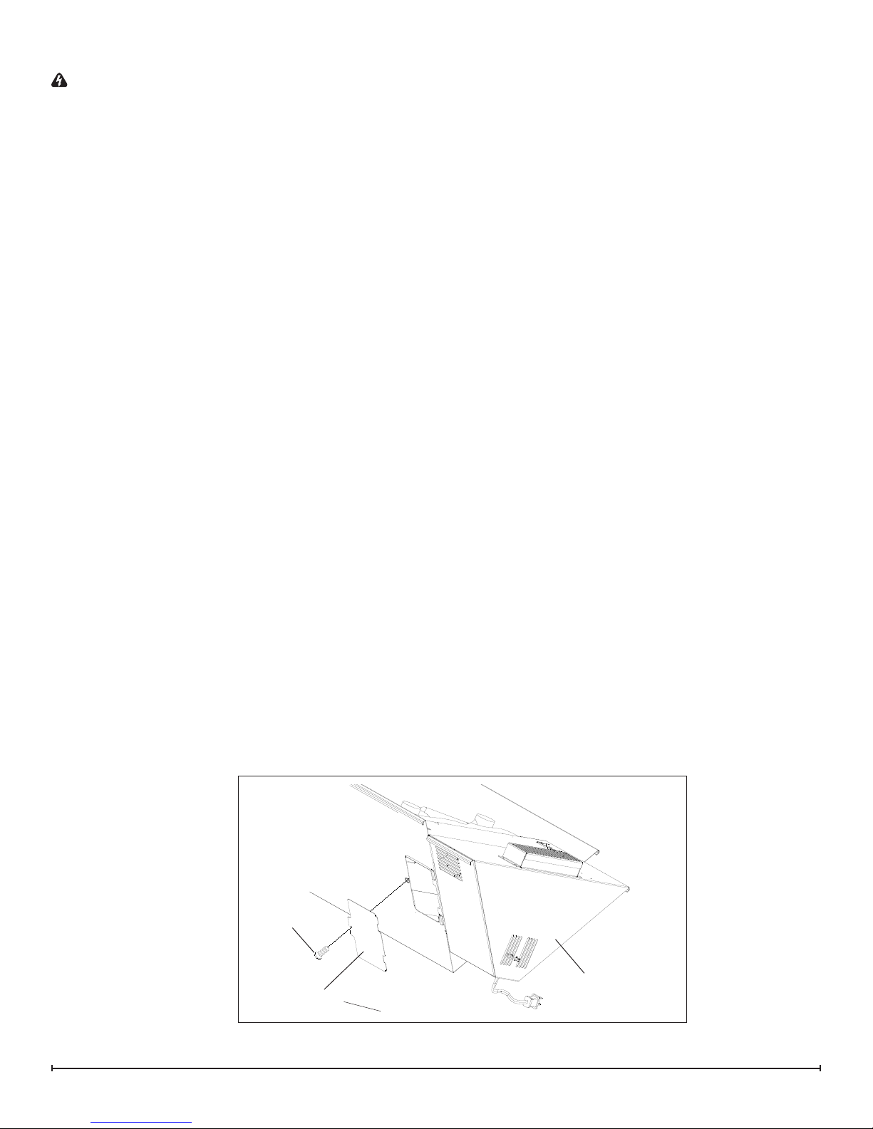
Replacement:
1. Unplug the unit from the outlet.
2. Remove the rear door from the left side of the unit by
unfastening one (1) Phillips screw (Figure 3). Set the
door and screw aside.
3. Reach inside opening to remove the bulb(s). Remove
the nearest bulb before attempting to remove the
further bulb. Bulbs are unscrewed in counter-clockwise
direction.
4. Insert new bulb(s).
5. Replace rear door and fasten in place.
6. Plug in the Corner Standing Stove.
Figure 3
Screw
Rear Door
4 www.dimplex.com
Bottom of unit
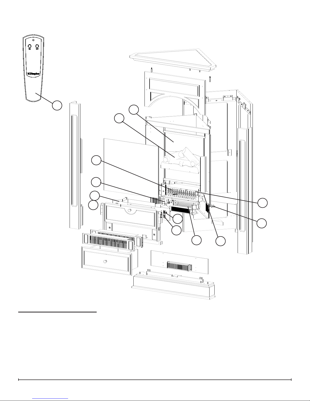
EXPLODED PARTS DIAGRAM
13
8
10
6
5
1
3
4
9
7
11
2
12
Replacement Parts List
Replacement Part:
Log Set1. . . . . . . . . . . . . . . . . . . . . . . . . .0439040100RP
Flicker Motor2. . . . . . . . . . . . . . . . . . . . . .2000140300RP
Reector Assembly3. . . . . . . . . . . . . . . . .5900080600RP
Light Harness4. . . . . . . . . . . . . . . . . . . . .2500170200RP
Partially Reective Glass5. . . . . . . . . . . . .5900470100RP
Thermostat6. . . . . . . . . . . . . . . . . . . . . . 2300150100RP*
3-Position Switch7. . . . . . . . . . . . . . . . . . . 2800071100RP
Thermostat Control Knob8. . . . . . . . . . . .8800620100RP
Heater ON/OFF Switch9. . . . . . . . . . . . . .2800070700RP
Remote Control Receiver10. . . . . . . . . . . .3000380200RP
Blower and Heater Assembly11. . . . . . . . .2000230100RP
Power Cord12. . . . . . . . . . . . . . . . . . . . . . .4100010300RP
Remote Control13. ...................3000370500RP
5

WIRING DIAGRAM
01
Lampholder
wire
assembly
3
RECEIVER,
REMOTE CONTROL
Flicker
Motor
Cord
Wide blade (N)
Narrow Blade (L)
Switch
Lamp
Switch
THERMOSTAT
1212
Blower
Motor
Wire from Cutout
24 GA - Red
Element
Bank
Wire of wide
blade of plug
6 www.dimplex.com
 Loading...