

Page 1
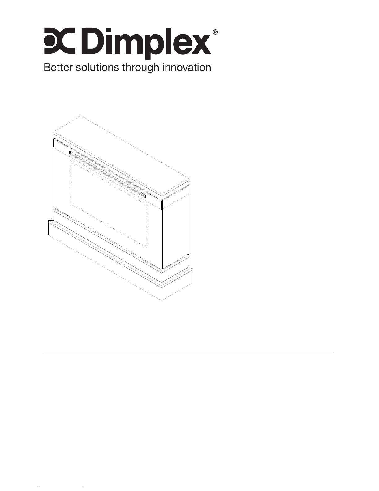
Owner’s Manual
Model
DCF44
To view the full line of Dimplex products, please visit
www.dimplex.com
7210050100R04
IMPORTANT SAFETY INFORMATION: Always read this manual rst
before attempting to install or use this replace. For your safety, always
comply with all warnings and safety instructions contained in this manual
to prevent personal injury or property damage.
Page 2
2 www.dimplex.com
Table of Contents
Always use a qualied technician
or service agency to repair
this replace.
!
NOTE: Procedures and
techniques that are
considered important
enough to emphasize.
CAUTION: Procedures and
techniques which, if not
carefully followed, will result
in damage to the equipment.
WARNING: Procedures
and techniques which, if not
carefully followed, will expose
the user to the risk of re,
serious injury, or death.
Welcome & Congratulations ...................3
IMPORTANT INSTRUCTIONS ..................4
Installation ..................................7
Operation ................................... 8
Maintenance ............................... 13
Warranty .................................16
Replacement Parts ..........................18
Page 3
3
Welcome & Congratulations
Thank you and congratulations for choosing to purchase an electric
replace from Dimplex, the world leader in electric replaces.
Please carefully read and save these instructions.
CAUTION: Read all instructions and warnings carefully before
starting installation. Failure to follow these instructions may result in a
possible electric shock, re hazard and will void the warranty.
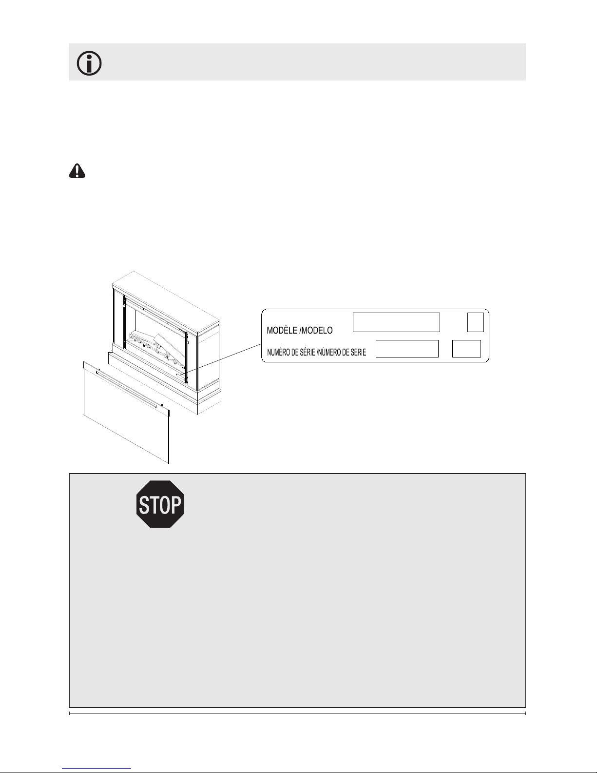
Please record your model and serial numbers below for future
reference: model and serial numbers can be found on the Model and
Serial Number Label of your replace.
NO NEED TO RETURN TO THE STORE
Questions with operation or assembly? Require Parts Information?
Product Under Manufacturer’s Warranty?
Contact us at: www.dimplex.com/customer_support
For Troubleshooting and Technical Support
OR Toll-Free 1-888-DIMPLEX (1-888-346-7539)
Monday to Friday 8:00 a.m. to 4:30 p.m. EST
Please have your model number and product serial
number ready. (See above)
S E R IA L No.
MODE L
MOD.
Page 4

4 www.dimplex.com
When using electrical appliances,
basic precautions should always
be followed to reduce the risk of
fire, electric shock, and injury to
persons, including the following:
① Read all instructions before
using the electric replace.
② The heater is hot when in use.
To avoid burns, do not let bare
skin touch hot surfaces. The trim
around the heater outlet becomes
hot during heater operation.
③ Extreme caution is neces-
sary when any heater is used by
or near children or invalids and
whenever the unit is left operating
and unattended.
④ Always unplug the electric
replace when not in use.
⑤ Do not operate any heater
after it malfunctions. Disconnect
power at the service panel and
have the heater inspected by a
reputable electrician before reusing.
⑥ Do not operate any unit with
a damaged cord or plug, or if the
heater has malfunctioned, or if
the electric replace has been
dropped or damaged in any manner, contact Dimplex Technical
Service at 1-888-346-7539.
⑦ Do not use outdoors.
IMPORTANT INSTRUCTIONS
⑧ The electric replace is not
intended for use in bathrooms,
laundry areas and similar indoor
locations. Never locate heater
where it may fall into a bathtub or
other water container.
⑨ Do not run the cord under
carpeting. Do not cover cord with
throw rugs, runners, or the like.
Arrange cord away from traf-
c area and where it will not be
tripped over.
⑩ To disconnect the unit, turn
the controls off, then remove the
plug from the outlet.
⑪ Do not insert or allow foreign
objects to enter any ventilation
or exhaust opening as this may
cause an electric shock or re, or
damage to the heater.
⑫ To prevent a possible re, do
not block air intake or exhaust in
any manner. Do not use on soft
surfaces, like a bed, where openings may become blocked.
⑬ All electrical heaters have
hot and arcing or sparking parts
inside. Do not use in areas where
gasoline, paint, or ammable
liquids are used or stored.
⑭ Do not modify the electric
replace. Use it only as described
in this manual. Any other use not
recommended by the manufactur-
Page 5

5
SAVE THESE INSTRUCTIONS
IMPORTANT INSTRUCTIONS
er may cause re, electric shock
or injury to persons.
⑮ Always plug heaters directly
into a wall outlet/receptacle.
Never use with an extension cord
or relocatable power tap (outlet/
power strip).
⑯ Do not burn wood or other
materials in the electric replace.
⑰ Do not strike the replace
glass.
⑱ Always use a certied electri-
cian should new circuits or outlets
be required.
⑲ Always use properly ground-
ed, fused and polarized outlets.
⑳ Disconnect all power supply
before performing any cleaning,
maintenance or relocation of the
unit.
㉑ When transporting or storing
the unit and cord, keep in a dry
place, free from excessive vibration and store so as to avoid damage.
WARNING: Remote control
contains small batteries. Keep
away from children. If swallowed,
seek medical attention immediately.
WARNING: Do not install bat-
tery backwards, charge, put in re
or mix with used or other battery
types - may explode or leak causing injury.
!
NOTE: Changes or modica-
tions not expressly approved by
the party responsible for compliance could void user's authority to
operate the equipment.
CAUTION
RISK OF ELECTRIC SHOCK
DO NOT OPEN
NO USER-SERVICEABLE PARTS INSIDE
Page 6

6 www.dimplex.com
IMPORTANT INSTRUCTIONS
CAUTION: This equipment has been
tested and found to comply with the limits
for a Class B digital device, pursuant to
Part 15 of the FCC Rules. These limits
are designed to provide reasonable
protection against harmful interference in
a residential installation. This equipment
generates uses and can radiate radio
frequency energy and, if not installed and
used in accordance with the instructions,
may cause harmful interference to radio
communications. However, there is no
guarantee that interference will not occur
in a particular installation. If this equipment
does cause harmful interference to radio
or television reception, which can be
determined by turning the equipment off
and on, the user is encouraged to try to
correct the interference by one of the
following measures:
• Reorient or relocate the receiving
antenna.
• Increase the separation between the
equipment and receiver.
• Connect the equipment into an outlet
on a circuit different from that to
which the receiver is connected.
• Consult the dealer or an experienced
radio/TV technician for help.
This device complies with Part 15 of the
FCC Rules. Operation is subject to the
following two conditions: (1) This device
may not cause harmful interference,
and (2) this device must accept any
interference received, including
interference that may cause undesired
operation.
FCC CAUTION: Any changes or
modications not expressly approved by
the party responsible for compliance could
void the user's authority to operate this
equipment.
This device complies with Industry
Canada licence-exempt RSS standard(s).
Operation is subject to the following
two conditions: (1) this device may not
cause interference, and (2) this device
must accept any interference, including
interference that may cause undesired
operation of the device.
Under Industry Canada regulations, this
radio transmitter may only operate using
an antenna of a type and maximum (or
lesser) gain approved for the transmitter
by Industry Canada. To reduce potential
radio interference to other users, the
antenna type and its gain should be so
chosen that the equivalent isotropically
radiated power (e.i.r.p.) is not more
than that necessary for successful
communication.
Page 7
7
Installation
WARNING: Ensure the power
cord is not installed so that it is
pinched or against a sharp edge
and ensure that the power cord is
stored or secured to avoid tripping
or snagging to reduce the risk
of re, electric shock or injury to
persons.
WARNING: Construction
and electrical outlet wiring must
comply with local building codes
and other applicable regulations
to reduce the risk of re, electric
shock and injury to persons.
WARNING: Do not attempt
to wire your own new outlets or
circuits. To reduce the risk of re,
electric shock or injury to persons,
always use a licensed electrician.
WARNING: To reduce the risk
of re, do not store or use gasoline or other ammable vapors or
liquids in the vicinity of the heater.
1. Select a suitable location that
is not susceptible to moisture
and is away from drapes,
furniture and high trafc.
CAUTION: High temperature,
risk of re, keep electrical
cords, drapery, furnishings,
and other combustibles at
least 3 feet (0.9 m) from the
front of the heater.
2. For ease of electrical hook
up you may wish to locate
the replace near an existing
outlet.
!
NOTE: A 15 Amp, 120 Volt
circuit is required. A dedicated
circuit is preferred but not essential in all cases. A dedicated circuit
will be required if, after installation, the circuit breaker trips or
fuse blows on a regular basis
when the heater is operating. Additional appliances on the same
circuit may exceed the current
rating of the circuit breaker.
3. Store the replace in a safe
dry and dust free location.
!
NOTE: The dimensions of the
replace are 44 in. (1118 mm)
wide x 34 in. (883 mm) high x
11 5/8 in. (295 mm) deep. The
replace does not require any
additional venting.
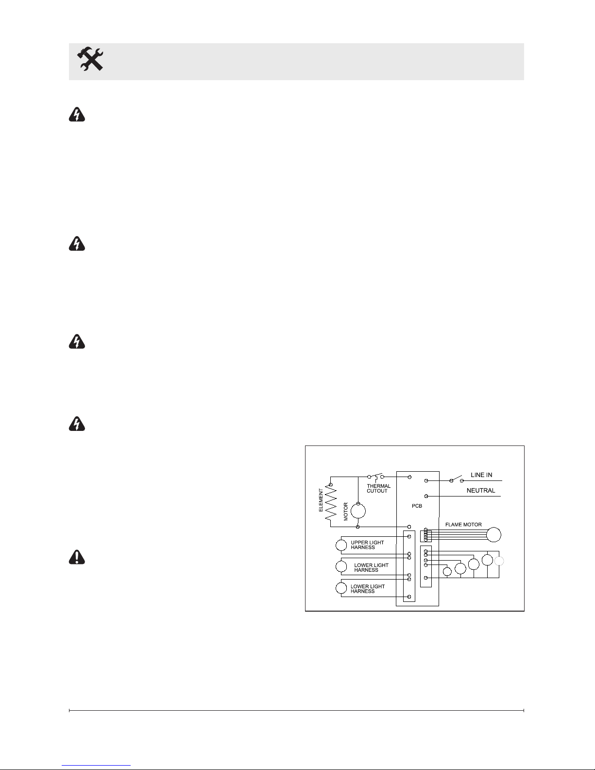
LOGSET LED LIGHTS
Wiring
Page 8
8 www.dimplex.com
Operation
WARNING: This electric
rebox must be properly installed
before it is used.
Manual Controls
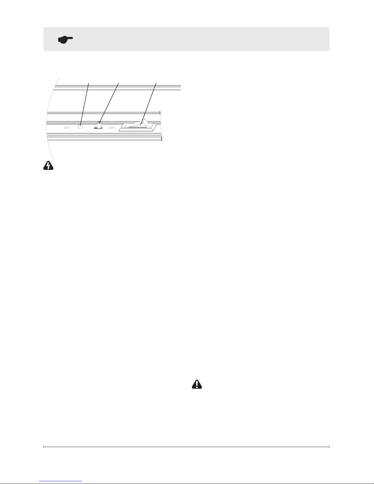
The manual controls for the
replace are located in the upper
right hand corner (Figure 1).
A. On/Off Switch
Supplies power to the 3-position
manual control switch.
B. 3-Position Switch
Remote (left position): The
unit is operated with the
remote control.
Flame (center position): The
ame effect is turned ON.
Flame & Heat (right
position): The ame effect
and heater are turned ON
simultaneously. When the
manual control is in the Flame
& Heat position the heater
does not run on the remote
operated thermostat.
!
NOTE: When the 3-position
switch is in the Flame and
Flame & Heat positions, the
replace unit will not operate
with the remote control.
C. Initialization Button
Used to synchronize the remote
control.
!
NOTE: The heater on your
replace may emit a slight,
harmless odor when rst used.
This odor is a normal condition
caused by the initial heating of
internal heater parts and will not
occur again.
Resetting The
Temperature Cutoff
Switch
Should the heater overheat, an
automatic switch will turn the
heater off and it will not come
back on without being reset. The
temperature cutoff switch can
be reset by unplugging the unit,
waiting ve minutes and plugging
the unit back in.
CAUTION: If you need to
continuously reset the heater,
unplug the unit and call Dimplex
North America Limited at 1-888346-7539. Please have your
Figure 1
ABC
Page 9
9
model and serial number ready
when calling.
Remote Control
The remote control has a range
of approximately 50 feet (15.25
m), it does not have to be pointed
at the replace and can pass
through most obstacles (including
walls). It is supplied with 243
independent frequencies to
prevent interference with other
units.
Battery Installation
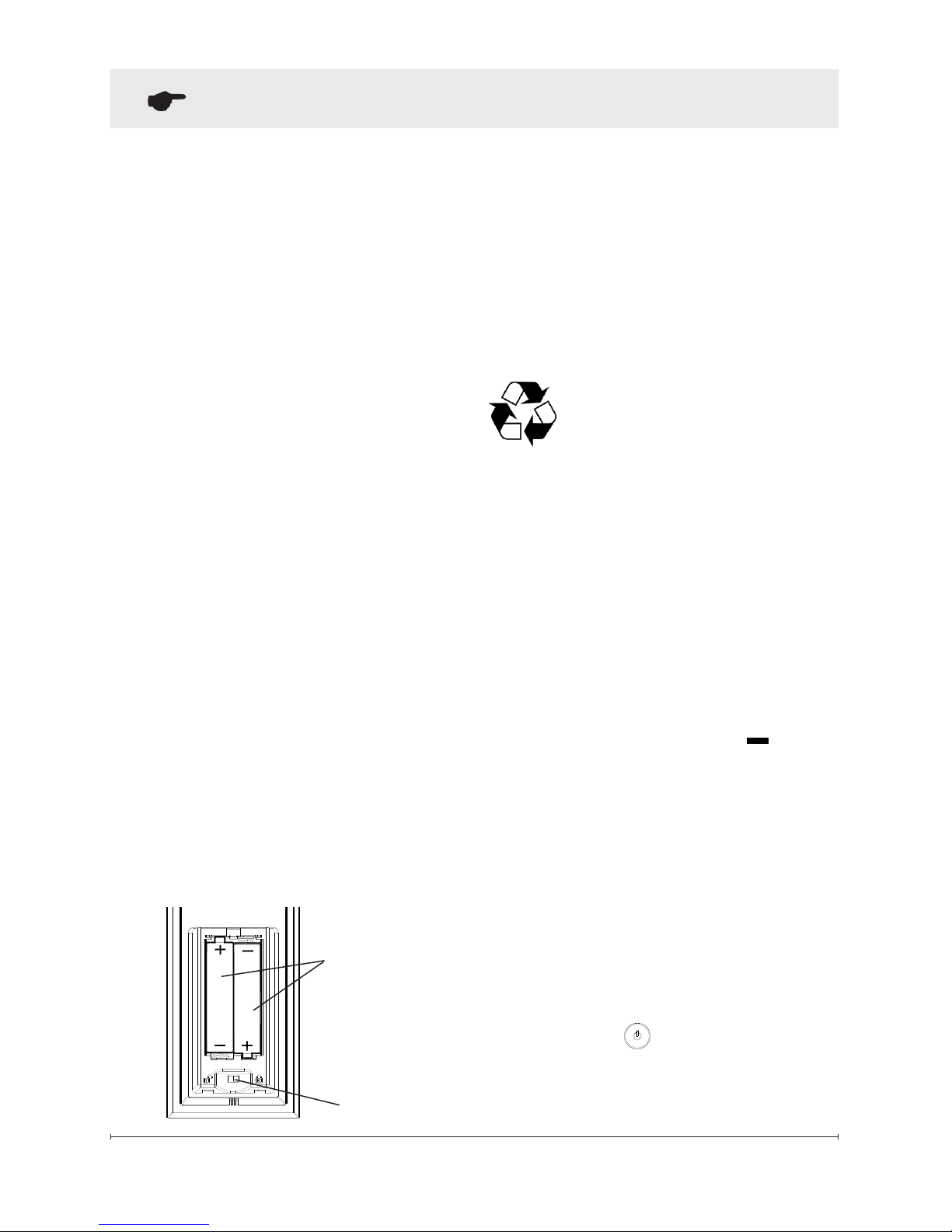
1. Depress tab on the battery
cover on the back of the
remote control and remove
battery cover (Figure 2).
2. Install two AAA batteries into
the remote control (included).
3. Ensure child lock is in the
“unlocked” position.
4. Replace the battery cover.
!
NOTE: When the “BAT”
symbol is present on the remote
control it is recommended to
replace the batteries promptly,
to maintain full functionality of
the remote/replace. The remote
control has a battery backup time
of only several hours.
Battery must be recycled
or disposed of properly.
Check with your Local
Authority or Retailer for recycling
advice in your area.
Remote Control Initializing/
Reprogramming
1. Plug cord into 120 Volt wall
outlet.
2. Ensure the On/Off switch
located in the switch box on
the replace in the upper right
hand corner is in the
ON
position.
3. Set the 3 position manual
control to the Remote
position (right position).
4. Press and hold the
initialization button on the
unit.
5. While holding the initialization
button, press the Flame/Heat
ON/OFF button on the
remote control.
6. Release the initialization
Operation
Figure 2
Batteries
Child Lock
Page 10
10 www.dimplex.com
Operation
button on the unit.
7. Press the Flame/Heat On/Off
button to turn the Flame/
Heat function ON.
Frequency Interference
If the replace does not respond
properly to the remote control,
the remote operating frequency
may have to be reset. The
remote control can send another
frequency code to the circuit
board to eliminate interference.
1. Simultaneously press the
“Temperature Down” button
and the “Flame Speed
Down” button on the remote
control.
2. “COD” will appear in place of
the sleep timer digits.
3. Release the “Temperature
Down” button and the “Flame
Speed Down” button.
4. Press the initialization button
on the unit.
5. Press the button on the
remote.
Your remote will now
have a different frequency
communicating with the replace.
Remote Control Functions
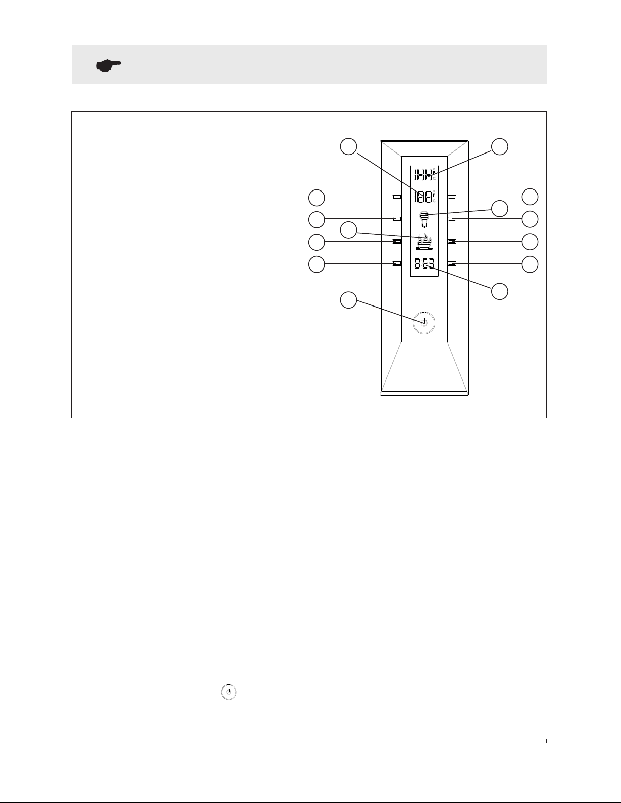
(All letter references are to Figure 6)
B. Set Temperature
Press F button to turn replace on.
Press H to raise thermostat.
Press G to lower thermostat.
Press both H and G to change
°F to °C.
C. Dimmer
Press the F button to turn
the Flame/Heat on.
Repeatedly press the J or I
button to decrease or increase
the brightness of the upper
lights.
D. Flame Speed
Press the F button to turn
the Flame/Heat on.
Press the L button to increase
the speed of the ame.
Press the K to decrease the
speed of the ame.
E. Sleep Timer
The Sleep Timer automatically
shuts off the replace after a
preset time (from 30 minutes
to 8 hours).
Press the F button to turn
the replace on.
Page 11
11
Operation
Figure 3 - Remote Control Functions
11
10
12
9
2
5
1
4
7
3
1413
8
6
A. Room Temperature
B. Set Temperature
C. Dimmer
D. Flame Speed Control
E. Sleep Timer
F. Flame & Heat On/Off
G. Temperature Down
H. Temperature Up
I. Dimmer Down
J. Dimmer Up
K. Flame Speed Down
L. Flame Speed Up
M. Sleep Timer Down
N. Sleep Timer Up
To set the sleep timer press
the N button.
Set the timer from 30 minutes
through 8 hours. The replace
will automatically turn off when
the sleep timer reaches zero
(0) minutes.
The Sleep Timer can be cancelled at any time by pressing
the M button repeatedly until
the sleep timer displays nothing.
F. Flame & Heat On/Off Button
Press the F button to turn
the Flame/Heat function on.
When B is higher then A the
heat will come on. To turn the
heat off, lower the B so that
it’s setting is lower then the A.
The default temperature setting is 72°F (22°C).
!
NOTE: When using the remote control the heater runs
on a thermostat. Press the H
or G buttons to adjust the set
temperature. Once the desired
set temperature is reached the
heater will turn off. The heater
will cycle on and off to maintain the desired set temperature.
Page 12
12 www.dimplex.com
Operation
Figure 4
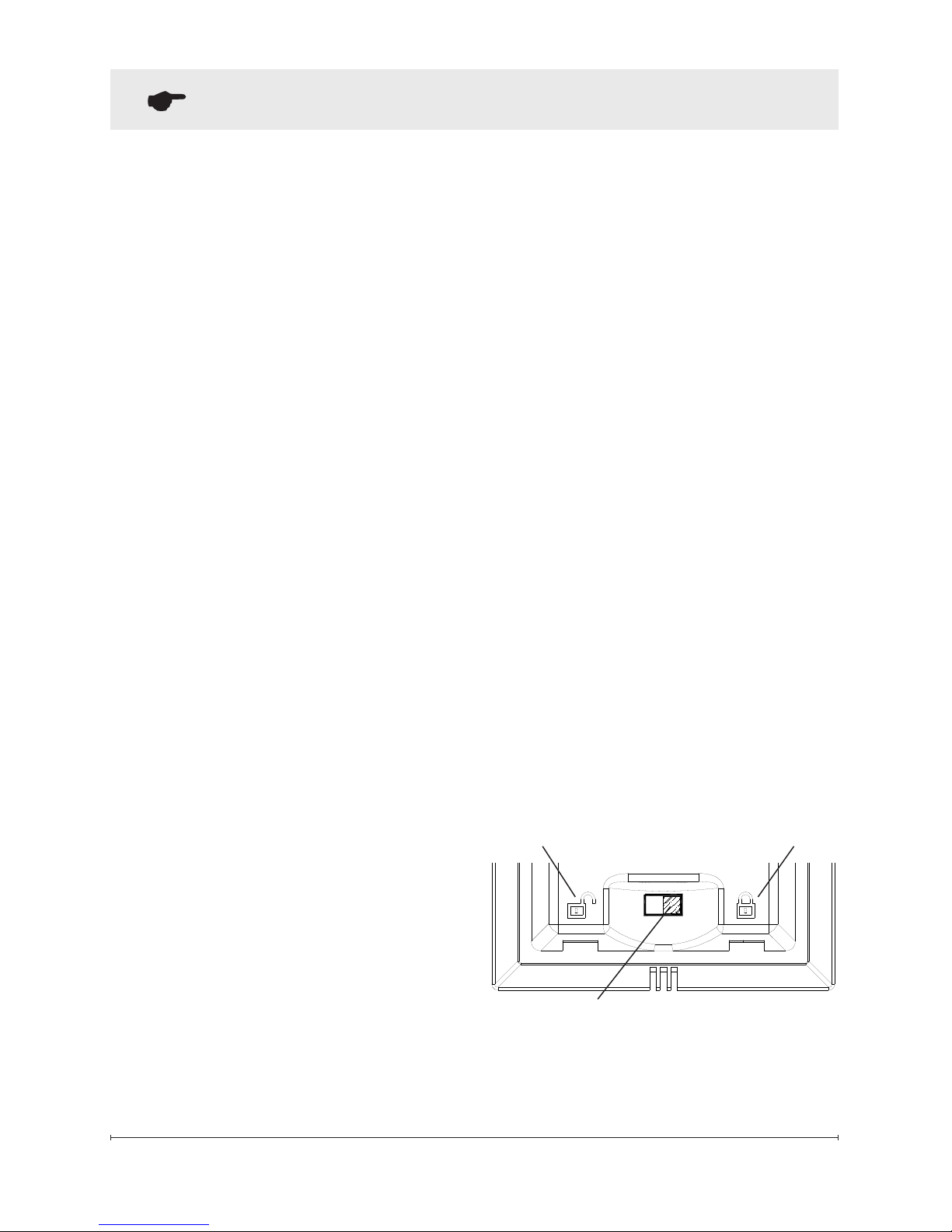
Unlocked
Locked
Child Lock Tab
Disable Heat
If desired, depending on the season, the heater on the unit can be
disabled. The unit will operate in
the same fashion, with remainder
of the controls.
To Disable - Press M and H at
the same time. The temperature setting on the remote will
no longer be visible.
!
NOTE: The heat will not work
in manual controls either.
To Enable - Press I and K at the
same time. The temperature
setting will now be visible
again.
Child Lock (Figure 4)
1. Depress tab on the battery
cover on the back of the remote control and remove the
battery cover (Figure 3).
2. Move Child Lock tab to
the right to lock the remote
control.
3. Move Child Lock tab back to
the left to unlock the remote
control.
4. Replace the battery cover.
!
NOTE: To temporarily unlock
the remote control press (in order)
G then H then I.
When the remote control’s backlight is illuminated the Child Lock
is bypassed. When the backlight
is off the Child Lock is re-activated.
Page 13
13
Maintenance
WARNING: Disconnect power
before attempting any maintenance or cleaning to reduce
the risk of re, electric shock
or damage to persons.
!
NOTE: The replace should
not be operated with an accumulation of dust or dirt on or in the
unit, as this can cause a build up
of heat and eventual damage. For
this reason the heater must be
inspected regularly, depending
upon conditions and at least at
yearly intervals.
Light Bulb Replacement
!
NOTE: Light bulbs need to be
replaced when you notice a dark
section of the ame or when the
clarity and detail of the log ember
bed exterior disappears. There
are three bulbs under the log set,
which generate the ames and
embers, and two bulbs above the
log that illuminate the log exterior.
Lower Light Bulb Requirements
Quantity of three clear chandelier
or candelabra bulbs with an E-12
(small) socket base, 60 Watt rating. Example: GE 60BC or Philips
60 CTC. Do not exceed 60
Watts per bulb
Figure 5
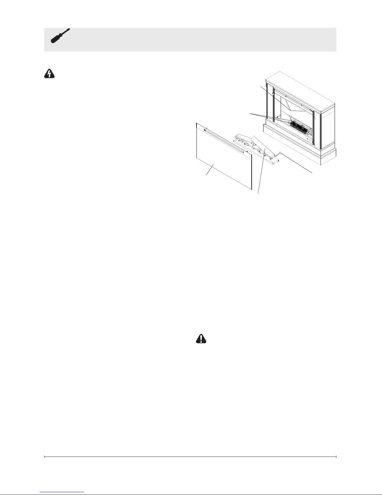
Upper Bulbs
Log Set
Lower Bulbs
LED
Wire Harness
Front
Glass
Helpful Hints: It is a good idea to
replace all light bulbs at one time
if they are close to the end of their
rated life. Group replacement will
reduce the number of times you
need to open the unit to replace
light bulbs. Care must be taken
when removing the logset as the
logset contains LED’s and wires.
To access the lower light bulb
area (Figure 5):
CAUTION: Allow at least
ve minutes for light bulbs to cool
before touching bulbs to avoid accidental burning of skin.
1. Remove front glass assembly.
2. Pull the front edge of the plas-
tic ember bed or plastic grate
up and forward until the rear
tab releases from the ledge
located at the bottom of the
Page 14
14 www.dimplex.com
Maintenance
partially reective glass.
!
IMPORTANT: Only handle the
log set by the ember bed.
!
NOTE: Log set ts tightly into
rebox, some force may be nec-
essary to remove.
3. Set log set in front of replace.
4. Disconnect the log set LED
wire harness from unit.
5. Gently pull the icker rod to
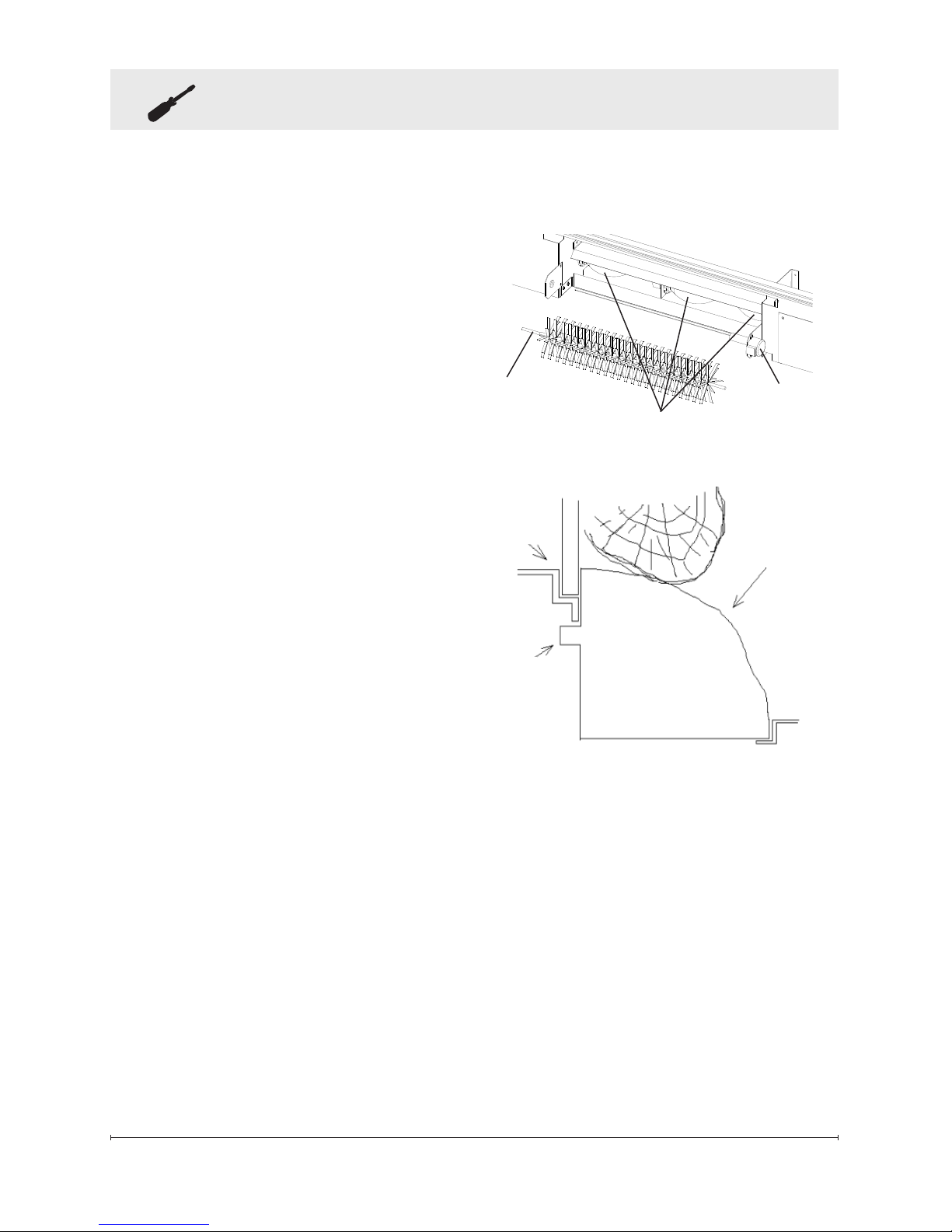
the right as far as possible
into the rubber bushing on the
icker motor shaft (Figure 7).
6. Unscrew bulbs counter clockwise.
7. Insert new bulbs.
8. Reconnect the icker rod and
the log set LED wire harness.
9. Install the log set by placing
the front, bottom edge of the
ember bed in the track behind
the front panel. Once in
place, push down on the back
edge of the ember bed until
the rear tab snaps into place
under the partially reective
glass (Figure 7).
!
NOTE: Ensure the log set is
installed tightly under the back
ledge to prevent light leakage.
10. Replace glass assembly.
Back
Ledge
Log
Ember bed
Rear
Tab
Front
Edge
Side Section
Figure 7
Figure 6
Exploded view to show detail
Flicker Rod
Flicker
Motor
Bulbs (3)
Page 15

15
Maintenance
Upper Light Bulb Requirements
Quantity of two (2) clear chandelier or candelabra bulbs with an
E-12 (small) socket base, 15 Watt
rating.
Do not exceed 15 Watts per
bulb
To access the upper light bulb
area (Figure 5):
CAUTION: Allow at least ve
(5) minutes for light bulbs to cool
before touching bulbs to avoid accidental burning of skin.
1. Remove front glass assembly.
2. Remove upper light cover.
3. Upper bulbs located in the
upper left and upper right cor-
ners of replace (Figure 5).
4. Unscrew bulbs counter clock-
wise.
5. Insert new bulbs.
6. Re-install upper light bracket.
7. Replace glass assembly.
Glass Cleaning
The glass is cleaned in the factory
during the assembly operation.
During shipment, installation,
handling, etc., the glass may collect dust particles; these can be
removed by dusting lightly with a
clean dry cloth.
To remove ngerprints or other
marks, the glass can be cleaned
with a damp cloth. To prevent
scratching, do not use abrasive
cleaners or spray liquids on the
glass surface.
Fireplace Surface Cleaning
Use a cloth dampened with warm
water only to clean painted sur-
faces of the electric replace. Do
not use abrasive cleaners.
Page 16

16 www.dimplex.com
Products to which this limited warranty
applies
This limited warranty applies to your newly
purchased Dimplex electric compact replace. This limited warranty applies only to
purchases made in any province of Canada except for Yukon Territory, Nunavut,
or Northwest Territories or in any of the
50 States of the USA (and the District of
Columbia) except for Hawaii and Alaska.
This limited warranty applies to the original
purchaser of the product only and is not
transferable.
Products excluded from this limited warranty
Light bulbs are not covered by this limited
warranty and are the sole responsibility of
the owner/purchaser. Products purchased
in Yukon Territory, Nunavut, Northwest
Territories, Hawaii, or Alaska are not covered by this limited warranty. Products
purchased in these States, provinces, or
territories are sold AS IS without warranty
or condition of any kind (including, without
limitation, any implied warranties or condi-
tions of merchantability or tness for a
particular purpose) and the entire risk of
as to the quality and performance of the
products is with the purchaser, and in the
event of a defect the purchaser assumes
the entire cost of all necessary servicing
or repair.
What this limited warranty covers and for
how long
Products covered by this limited warranty
have been tested and inspected prior to
shipment and, subject to the provisions
of this warranty, Dimplex warrants such
products to be free from defects in material and workmanship for a period of 12
months from the date of the rst purchase
of such product.
The limited 12 month warranty period also
applies to any implied warranties that may
exist under applicable law. Some jurisdictions do not allow limitations on how long
an implied warranty lasts, so the above
limitation may not apply to the purchaser.
What this limited warranty does not cover
This limited warranty does not apply to
products that have been repaired (except
by Dimplex or its authorized service representatives) or otherwise altered. This
limited warranty does further not apply
to defects resulting from misuse, abuse,
accident, neglect, incorrect installation, improper maintenance or handling, or operation with an incorrect power source.
What you must do to get service under
this limited warranty
Defects must be brought to the attention
of Dimplex Technical Service by contacting Dimplex at 1-888-346-7539, or 1367
Industrial Road, Cambridge Ontario,
Canada N1R 7G8. Please have proof of
purchase, catalogue/model and serial
numbers available when calling. Limited
warranty service requires a proof of purchase of the product.
What Dimplex will do in the event of a
defect
In the event a product or part covered by
this limited warranty is proven to be defective in material or workmanship during the
12 month limited warranty period you have
the following rights:
• Dimplex will in its sole discretion either
repair or replace such defective product or part without charge. If Dimplex
is unable to repair or replace such
product or part, or if repair or replace-
Warranty
Page 17

17
ment is not commercially practicable
or cannot be timely made, Dimplex
may, in lieu of repair or replacement,
choose to refund the purchase price
for such product or part.
• Limited warranty service will be performed solely by dealers or service
agents of Dimplex authorized to provide limited warranty services.
• The purchaser is responsible for
removal and transportation of such
product or part (and any repaired or
replacement product or part) to and
from the authorized dealer’s or service
agent’s place of business.
• This limited warranty does not entitle
the purchaser to on-site or in-home
services. On-site or in-home services
may be performed at the purchaser’s
specic request and expense at Dimplex’s then-current rates for such services.
• Dimplex will not be responsible for,
and the limited warranty services shall
not include, any expense incurred for
installation or removal of the product
or part (or any replacement product or
part) or any labour or transportation
costs. Such costs shall be the purchaser’s responsibility.
What Dimplex and its dealers and service
agents are also not responsible for:
IN NO EVENT WILL DIMPLEX, OR ITS
DIRECTORS, OFFICERS, OR AGENTS,
BE LIABLE TO THE PURCHASER OR
ANY THIRD PARTY, WHETHER IN CON-
TRACT, IN TORT, OR ON ANY OTHER
BASIS, FOR ANY INDIRECT, SPECIAL,
PUNITIVE, EXEMPLARY, CONSEQUENTIAL, OR INCIDENTAL LOSS, COST,
OR DAMAGE ARISING OUT OF OR
Warranty
IN CONNECTION WITH THE SALE,
MAINTENANCE, USE, OR INABILITY
TO USE THE PRODUCT, EVEN IF DIMPLEX OR ITS DIRECTORS, OFICERS ,
OR AGENTS HAVE BEEN ADVISED OF
THE POSSIBILITY OF SUCH LOSSES,
COSTS OR DAMAGES, OR IF SUCH
LOSSES, COSTS, OR DAMAGES ARE
FORESEEABLE. IN NO EVENT WILL
DIMPLEX, OR ITS OFFICERS, DIRECTORS, OR AGENTS BE LIABLE FOR
ANY DIRECT LOSSES, COSTS, OR
DAMAGES THAT EXCEED THE PURCHASE PRICE OF THE PRODUCT.
SOME JURISDICTIONS DO NOT ALLOW
THE EXCLUSION OR LIMITATION OF INCIDENTAL OR CONSEQUENTIAL DAMAGES, SO THE ABOVE LIMITATION OR
EXCLUSION MAY NOT APPLY TO THE
PURCHASER.
How State and Provincial law apply
This limited warranty gives you specic
legal rights, and you may also have other
rights which vary from jurisdiction to jurisdiction. The provisions of the United Nations Convention on Contracts for the Sale
of Goods shall not apply to this limited
warranty or the sale of products covered
by this limited warranty.
Page 18

18 www.dimplex.com
© 2013 Dimplex North America Limited
Dimplex North America Limited
1367 Industrial Road
Cambridge ON
Canada N1R 7G8
Flicker Motor ...................................... 3000240200KIT
Flicker Rod ........................................5901250100RP
Heater Assembly (with cutout) ..........................2000330200RP
On/Off Switch ......................................2800070200RP
Remote Control Switchboard. . . . . . . . . . . . . . . . . . . . . . . . . . .3000300300RP
Remote Control . . . . . . . . . . . . . . . . . . . . . . . . . . . . . . . . . . . . .3001070100RP
Remote Control Receiver .............................3000880100RP
Power Cord ........................................4100040300RP
Log Set ...........................................0439070100RP
Partially Reective Glass ..............................5900910100RP
Lower Light Assembly ................................2500400100RP
Upper Light Assembly ................................2500400200RP
Replacement Parts
 Loading...