

Page 1
MODEL:DCB09(2.6kW Cooling / 2.4kW Heating)
DCB14(4.1kW Cooling / 3.6kW Heating)
IMPORTANT
Please read this owner’s manual carefully and thoroughly
before installing and operating your room air conditioner.
Please retain this owner’s manual for future reference after
reading it thoroughly.
Page 2
Table of Contents
Page
Introduction
Operating Instructions
Electrical Specifications
Installation Instructions
Care and Maintenance
Trouble Shooting Guide
2
4
5
6
9
10
- 1 -
Page 3
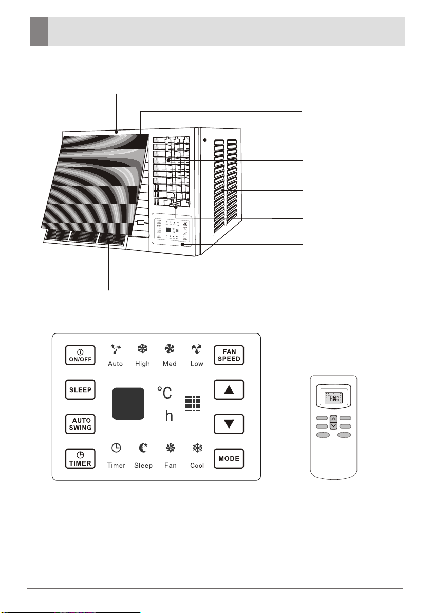
Introduction
Front Cover
Air inlet grille
(Indoor)
Cabinet
Air outlet grille
(Indoor)
Air inlet grille
(Outdoor)
Vent Lever
Control Panel
Air filter
Fig.1-1
Control Panel
- 2 -
Remo
SLEEP
TIMER ON
TMIER OFF
FEEL
COOL
DRY
FAN
SLEEP
TIMER
MODE
te Control
SWING
ON/OFF
AUTO
HIGH
MID
LOW
SWING
FAN
Page 4
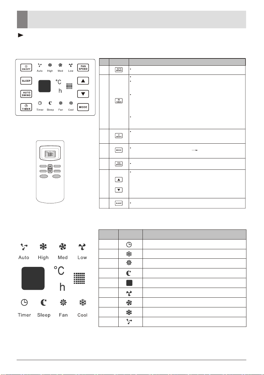
Operating Instructions
For remote control model
You can easily operate this air conditioner by pressing the relevant buttons on the
control panel as well as the remote controller.
No.
Button
Function
1
2
Control Panel
3
Used to adjust airflow direction.
Used to set or cancel timer operation.
When the unit is in operation, you can set OFF TIMER. When
the unit is off, you can set ON TIMER. Timer setting range is
0 to 24 hours.
If the OFF TIMER is set, the timer LED displays the remaining
time to turn off the unit for only 10 seconds, then LED shifts
to display set temperature.
If you press TIMER button within the 10 seconds, OFF TIMER
will be cancelled.
If the ON TIMER is set, the timer LED displays the remaining
time to turn on the unit. If you want to cancel ON TIMER, press
TIMER button.
Every time you press this button, the air conditioner will turn
on or will be stopped when it is in operation.
4
5
6
7
SLEEP
TIMER
SLEEP
TIMER ON
TMIER OFF
AUTO
FEEL
HIGH
COOL
MID
DRY
LOW
FAN
SWING
FAN
SWING
ON/OFF
MODE
Remote Control
Indication symbols of LED control panel
No.
1
2
3
4
5
6
7
8
9
Every time you press this button, the operation mode is
changed in sequence:COOLING > FAN ONLY > COOLING
Used to select fan speed in sequence auto, high, mid and low.
This button used to set room temperature in COOLING mode
or used to set time in TIMER mode. If the two keys are
pressed at the same time for more than three seconds, the
temperature LED display will alternate between C and. F
NOTE: Temperature setting range is from 16 to 31 degrees
Celsius
To activate the "SLEEP" function
Button
Function
Timer
Cooling
Fan only(only Cooling Unit)
Sleep
Display set temp./Display set timer
Low fan speed
Mid fan speed
High fan speed
Auto fan speed
Above LED lights on when the relevant mode is in used.
- 3 -
Page 5

Operating Instructions
Remote control
No.
Button
(TEMP UP)
1
(TEMP DN)
2
3
ON/OFF
4
5
6
8
9
FAN
TIMER
SLEEP
MODE
SWING
The display and some functions of the remot
model.
Function
Increase the temperature or time by 1 degree
Decrease the temperature or time by 1 degree
To switch the conditioner on and off.
To select the fan speed of auto/low/mid/high
To set automatic switching-on/off
To activate the function ¡°SLEEP¡±
To select the mode of operation
To activate or deactivate of the movement of the¡°DEFLECTORS¡±.
e control may vary according to the
The shape and position of buttons and indicators may va
but the functions are
The unit confirms the correct reception of
the same.
each press button with a beep.
- 4 -
ry according to the model,
Page 6

Electrical specifications
1. All wiring must comply with local and national
electrical codes and must be installed by a
qualified electrician. If you have any questions
regarding the following instructions, contact a
qualified electrician.
2. Check available power supply and resolve any
wiring problems BEFORE installing and
operating this unit.
3. For your safety and protection. This unit is
grounded through the power cord when plugged
into a matching wall outlet. If you are not sure
whether your wall outlet is properly grounded,
please consult a qualified electrician.
4. The rating plate on the unit contains electrical
and other technical data. The rating plate is
located on the right side of the unit. Make sure
to use correct power supply according to the
rating plate of your air conditioner.
DCB09 DCB14
Electric Shock Hazard
The air conditioner has a serial rating
volts. It must have its own fuse or
circuit breaker, and no other device or
unit should be operated on the fuse or
circuit breaker.
To avoid the possibility of personal
injury, disconnect power to the unit
before installing or servicing.
!
- 5 -
Page 7

Installation instructions
REMOVE ALL THE SHIPPING PARTS BEFORE INSTALLATION
LOCATION
Select a location that can support the weight of the air conditioner and one that will not
cause increased operation noise and vibration.
Direct sunlight is unfavorable for efficient cooling.
Select a place where there is no obstacles near the air inlet and outlet.
Less than 210
More than 55
wall thickness is less than 210
5-10mm
Make rear side lower so that waterwill drain out smoothy.
Less
210
than
Scrape
lf the wall thickness is more than 210 scrape the wall as
shown above.
more
than 400
more
than 500
45
more
than 400
less
than 210
- 6 -
Page 8

Installation instructions
CAUTION
Do not install air conditioner in the place where flammable gas leaks are a
possibility.
The minimum clearance from the appliance to combustible surfaces is 100mm;
(Only for e
The rang
OPERATION
Check the capacity of wiring and power outlet. The power outlet should be used
exclusively for the air conditioner. Do not use it with other appliances.
Ground the air conditioner to prevent danger of electric shock.
Connect the air conditioner with power source securely.
Use a fuse as below.
lectric heating)
e of external static pressures at which the appliance was tested is 0-5Pa
CAUTION
Before installation,turn off the operation switch and disconnect the power cord.
This appliance is not intended for use by persons(including children) with
reduced physical, sensory or
knowledge, unless they have been given supervision or instruction concerning use of the appliance by a person responsible for their safety. Children
should be supervised to ensure that they do not play with the appliance.
The appliance is fitted with means for disconnection from the supply mains
having a contact separation in all poles that provide full disconnection
under over voltage category III conditions, and these means must be
incorporated in the fixed wiring in accordance with the wiring rules.
mental capabilities,or lack of experience and
- 7 -
Page 9

Installation instructions
1) Remove the front panel. (Fig.5)
Remove the air filter. (Fig.6)
Remove screw at the botton of the front panel. (Fig.7)
Open the panel cover.
2) Remove the screws fix the chassis-fixing board and cabinet.
some Models have two more screws on the back of the
cabinet. (Fig.8)
3)
Grasp the handle on the front of the chassis and carefully
slide the air conditioner unit out of the cabinet. (Fig.9)
lnstall the drain tube connection into the hole provided
4)
at the rear of the air conditioner chassis.(Fig.11)
To meet different requirements of different type of air
conditioner, there are two kinds of methods for your choice
to treat the condensed water. You can choose back
drainage or bottom drainage.
Bottom drainage way: the drain tray is fixed in position
through four pcs of screws
the back drainage hole.(Fig.15)
Back drainage way using the flare nut to block the bottom
drainage hole and use water outlet pipe to connect the
back drainage hole pay attention to increase the sealing
ring to prevent water leakage.(Fig.16)
lnstall the air conditioner cabinet on the installation shelf
5)
(not included) with screws.(Fig.10)
6) Carefully slide the unit back into the cabinet.(Fig .12)
7) Reinstall the retaining bracket,front panel and mounting
screws.(Fig.8,7,13)
8) Reinstall the air filter.(Fig.14)
and use the flare nut to block
Screw
Fig.5
Fig.6
Fig.7
Fig.8
Fig.9
Wall
Cabinet
Installation shelf
Fig.10
Fig.14
Fig.11
drain tray
screw
- 8 -
Fig.12
Fig.15
falre nut
falre nut
sealing ring
water outlet pipe
Fig.13
Fig.16
Page 10

Care and Maintenance
AIR FILTER
The air filter should be washed at least once a month. lf the air filter remains
full of dust, the air flow will decrease and the cooling capacity will be reduced.
The filter is behind the cover and to be pulled out from right hand side.
Wash the air filter with water and detergent.
Rinse with clean water and dry completely before reinstalling.
Fig.15
CAUTION
Do not use hot water above 40 C f or w ashing t he a ir f ilter.
Let the filter dry thoroughly in the shade before reinstalling. Do not expose
it directly on the sun.
Do not operate the air conditioner with the filter removed.
T1 condition: The ambient temperature for cooling: 18~43 ;
The ambient temperature for heating: -5~20 .
T3 : The ambient temperature for cooling: 25~52 ;condition
The ambient temperature for heating: -5~20 .
AIR CLEANING FILTER
The air cleaning filter is attached to the air filter.
Wash the air cleaning filter as well when wash air
filter.
FRONT COVER,ETC
The front cover will accumulate dirt and dust.
To clean it, wipe it with a soft dry cloth. When
it is excessively dirty, wipe it with a soft cloth
dampened with warm water or mild soap, then
wipe it again thoroughly with a soft dry cloth.
Fig.16
Hot Water
Benzine,acid,etc.
- 9 -
Page 11
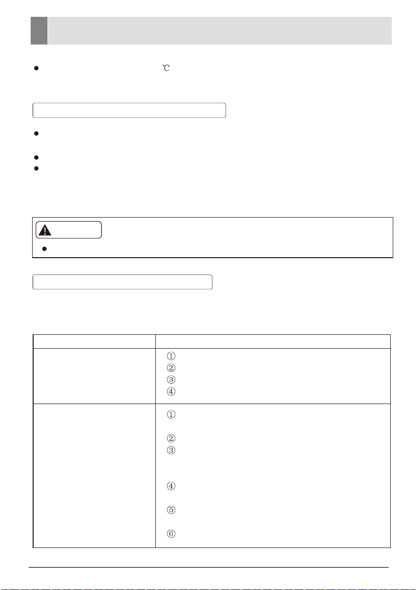
Troubleshooting Guide
Never use hot water above 50 ,benzine,gasoline,acid,thinner or brush to wipe off
dirt because they will damage the plastic surface and the coating.
LONG OFF PERIOD MAINTENANCE
Operate the fan alone ("LOW FAN"or"HIGH FAN") for half a day to dry out the
inside of the unit.
Turn off power and remove plug from wall socket.
After a long off period and going to use the air conditioner again , clean the
CONDENSER(at the rear)and EVAPORATOR (at the front)fins by using a soft
brush or vacuum cleaner.
CAUTION
Be careful not to damage the fins during the cleaning.
BEFORE ASKING FOR SERVICE
Check the following points before requesting for repairs or service. lf the malfunction
persists,pelase contact our customer service.
Faults Cause
Does not operate
Does not cool effectively
ls the power off?
ls the fuse blown?
ls the voltage extremely high or low?
ls the operation dial set to"off"?
ls the air filter remain full of dust or dirt?
See air filter instructions on page 9.
Is the sunlight fall directly on the unit?
ls the air flow on the rear side obstructed?
Leave a space of 500mm behind the rear side of
the air condition?
The doors or windows may be opened widely or
there are other sources of heat in the room?
The temperature dial may not set to the colder
position. Turn the dial further clockwise.
ls the ventilation damper opened?
- 10 -
Page 12

CONTACT DETAILS
Glen Dimplex Australia Pty Ltd
1340 Ferntree Gully Road
Scoresby VIC 3179
Australia
Ph: 1300 556 816
Web: www.dimplex.com.au
Glen Dimplex New Zealand Ltd
38 Harris Road
East Tamaki, Auckland
New Zealand
Ph: 09 274 8265
Web: www.dimplex.co.nz
 Loading...