

Page 1
r
IMPOR
TANT INFORMATION
POR
MODELS:
DC12 / DC12RC / DC15 / DC18
INSTRUCTION MANUAL
TABLE AIR CONDITIONER
Carefull
your portable air conditioner. Please retain this manual for
product warranty details and for future reference.
CA
1.
Make sure the inlet and outlet vents are never blocked.
2. Ensure the appliance is on a stable, even surface when operating to avoid
water leakage.
3. Do not operate this unit in an explosive or corrosive atmosphere.
4. When switched to cooling, only operate this unit in set temperatures between
17°C and 43°C. For heating, only operate this unit in ambient temperatures
between 5°C and 23°C.
5. Clean the air filter frequently to ensure efficient operation.
6. To prevent compressor damage when the unit has been operating and is
turned off, please wait at least 3 minutes before restarting.
7. This unit needs to be plugged into a 220-240V ~ 50Hz AC, 10 Amp power
outlet.
8. Do not use any extension cords with this unit.
9. This unit is for indoor use only.
10. Open the adjustable air vent and extend the exhaust pipe (and drain pipe, if fitted) to
the closest window before using.
11. Only ever have a professional technician, manufacturer or service agent
replace a damaged power cord.
12. The batteries from the remote control must be removed and disposed of
safely, before the appliance is scrapped.
13. This appliance is not intended for use by persons (including children) with reduc ed
physical, sensory or mental capabilities, or lack of experience and knowledge,
unless they have been given supervision or instruction concerning use of the
appliance by a person responsible for their safety.
14. Children should be supervised to ensure that they do not play with the appliance.
y read this instruction manual before you install or use
UTION
1
Page 2
IMPORTANT
The air co
In case of doubt we suggest you wait for at least 24 hours before
operation. (Please keep unit upright at all times)
ACKAGE CONTENTS
P
Port
able air conditioner
Remote control
Extendable window kit
nditioner must always be stored and transported upright.
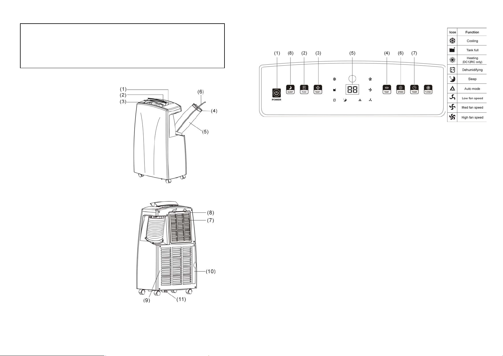
CONTROLS AND
ols for all models
Contr
DISPLAY
ARTS
P
1. Contro
2. Display screen
3. Adjustable air vent
4. Window kit adaptor
5. Exhaust tube
6. Drain hose (DC12RC only)
7. Cool air inlet
8. Cool air filter
9. Hot air inlet
10. Hot air filter
11. Drain plug
No
l panel
te: Make sure drain plug (11) is fitted before use.
1. POWER
※
The port
protects the unit from possible damage due to rapid starting and stopping of its
compressor. Compressor operation begins 3 minutes after the unit is switched on or the
mode is switched from dehumidify to air conditioning.
2. FUNCTION
3. TEMP+
4. TEMP-
※ The time t
the size of the space in which the unit is operating in.
For example, if the ambient temperature is too hot or the room is too large, the rate at
which the temperature descends will be slow as the cooling may be less effective.
able air conditioner is fitted with a compressor delay protection circuit. This
aken to reach the desired set temperature will depend on the environment and
Press the POW
Press this butto
(The heating function is only available on the DC12RC)
This button rais
pressed, to a maximum of 30°C. For DC12RC, it can be raised to a
maximum of 25°C.
This button lowers the set temp
pressed, to a minimum of 17°C. For DC12RC, it can be reduced to a
minimum of 15°C.
ER button to turn the unit "ON" or "OFF".
n to select cooling, heating or dehumidification.
es the set temperature by 1°C each time it is
erature by 1°C each time it is
2
3
Page 3

5. DISPLAY The display indicates the current set temperature or the time setting.
The timer can be used to turn the unit off automatically after a set
When the set temperature or the timer is adjusted, the new setting is
shown then the display returns to the current set temperature.
※ The display is also used to show error codes should a fault occur, see ERROR CODES.
6. FAN SPEED
Press FAN SPEED to select LOW, MEDIUM, HIGH or AUTO fan speed.
If AUTO fan speed is selected, the unit operates at maximum capacity
and high fan speed while the room temperature is more than 2°C from
the set temperature. When the room temperature is within 2°C of the set
temperature, the unit operates at medium capacity and fan speed. Once
the room temperature equals the set temperature, the unit will operate
at minimum capacity and low fan speed to efficiently maint ain the
desired temperature.
When HIGH, MEDIUM or LOW speed is selected, the unit operates at
maximum capacity until the set temperature is reached. The fan
operates at the selected speed
TURBO If the TURBO button is selected, the unit will operate at the highest
speed for 30 minutes before changing to AUTO mode. Press TURBO
or FAN SPEED button to cancel this function. If the unit is in TURBO
mode, the "AUTO" icon will be flashing.
7. TIMER ON/OFF button for the programmable timer.
The timer can be used to turn the unit on automatically after a set
time delay is complete.
1. With the unit OFF, press the "TIMER" button to set the desired time
delay before the unit is to start.
2. Choose the function desired (cooling, heating or dehumidification.)
3. Once the set time delay is complete, the unit will turn on
automatically.
4. If you press the “POWER” button before the time delay is complete,
the delay will be cancelled and the unit will turn on immediately.
time period is complete.
1. With the unit ON, press the "TIMER" button to set the desired time
for the unit to remain on.
2. Once the set time period is completed, the unit will turn off
automatically.
3. If you press the “POWER” button before the time delay is complete,
the delay will be cancelled and the unit will turn off immediately.
8. SLEEP Press the SLEEP button to select the sleep comfort mode.
When the unit is in cooling mode and sleep mode is selected, the unit
will raise the set temperature 1°C each hour to a maximum of 2°C over
two hours. These temperatures will be maintained for the balance of the
time set and help maximize sleep comfort.
When the unit is in heating mode and sleep mode is selected, the unit
will lower the set temperature 1°C each hour to a maximum of 2°C over
two hours. These temperatures will be maintained for the balance of the
time set and help maximize sleep comfort.
When setting the "sleep comfort" mode please ensure you set the
number of hours required by pressing the TIMER button. The hours set
will be shown on the display by pressing either the TEMP+ or TEMPbuttons. Please note: This function cannot be used in
dehumidifying mode.
The screen will be blank after 15 minutes of operation, but can be
re-activated when any key is pressed.
WATER DRAIN For cooling only models, the water drain warning indicator is displayed
when the internal condensation container requires emptying. For
reverse cycle models, an E4 error code will be displayed.
For more information, refer to WATER DRAIN
4
5
Page 4
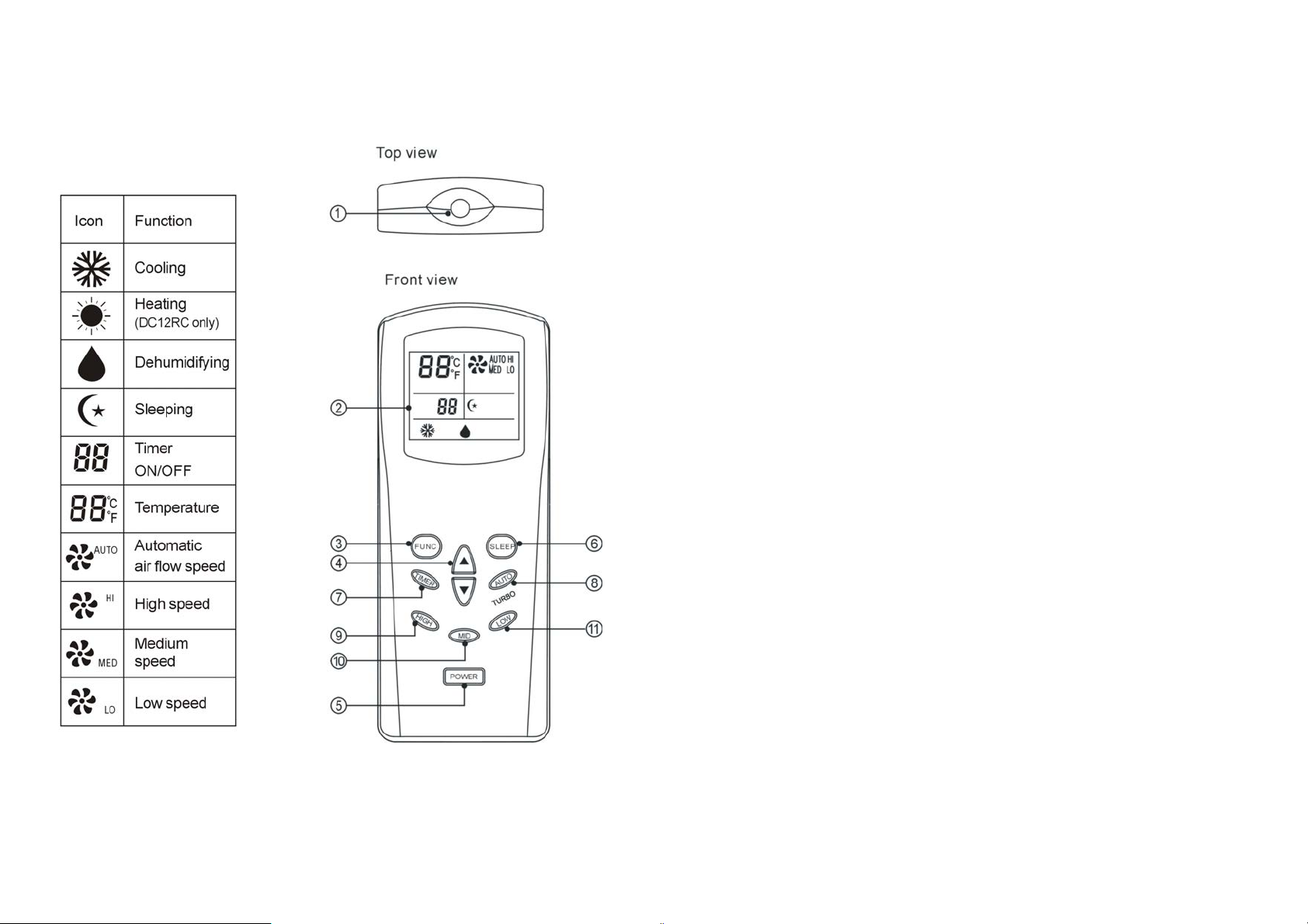
REMOTE CONTROL
REMOTE CONTROL
When a remo
te control signal is transmitted, the transmission icon on the
OPERATING INSTRUCTIONS
display flashes once, indicating the signal has been received.
ransmitter
1. T
2. Display
3. Function select key:
Press this butto
(The heating function is only available on the DC12RC)
4.
Setting keys for room temperature:
The set
the set temperature will fall by 1
function and can make the set temperature rise or fall continuously when you press and
hold the button down.
wer key:
5. Po
When this key
n to select cooling, heating or dehumidification.
temperature will rise by 1
is pressed, the memorized modes and preset information on the
o
hen the ▲ key is pressed once and subsequently
C w
o
hen the ▼ key is pressed. Both keys have a fast key
C w
temperature, speed, direction of airflow, sleep, etc. that is stored in the remote is
transmitted to the unit and it will operate accordingly. When the key is pressed again, the
unit will discontinue operation.
6
7
Page 5

6. Sleep
key
8. Auto
key
When this key
(1) Press the “SLEEP” key to set the sleep function; press again to cancel sleep
setting.
imer key:
7. T
TIMER-O
The timer can be used to turn the unit on automatically after a set time delay is
complete.
1. With the unit OFF, press the "TIMER" button to set the desired time delay before the
unit is to start.
2. Choose the function desired (cooling, heating or dehumidification.)
3. Once the set time delay is complete, the unit will turn on autom at ically.
4. If you press the “POWER” button before the time delay is complete, the delay will be
cancelled and the unit will turn on immediately.
TIMER-OFF:
The timer can be used to turn the unit off automatically after a set time period is
complete.
1. With the unit ON, press the "TIMER" button to set the desired time for the unit to
remain on.
2. Once the set time period is completed, the unit will turn off automatically.
3. If you press the “POWER” button before the time delay is complete, the delay will be
cancelled and the unit will turn off imm ediat ely.
is pressed, the air flow of the unit changes into sleep mode (low speed)
N:
8
Automatic fan s
Press this button to switch the unit to AUTO mode. Continue to press the AUTO button for
5 seconds to turn on the TURBO mode.
9. High
10. MID
11. Lo
key
Press this key
key
Press this key
w key
Press this key
peed.
to switch to High fan speed.
to switch to Medium fan speed
to switch to Low fan speed
9
Page 6
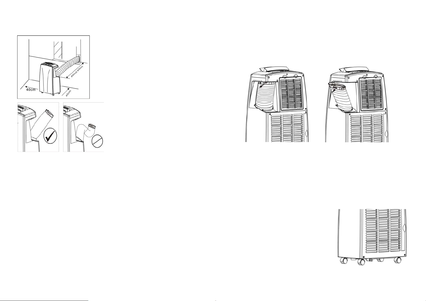
INSTALLATION
Locating the unit.
EXHAUST TUBE INSTALLATION
Install the portable air conditioner in a flat location
with adequate space to ensure the air inlets and
outlets will not be blocked.
Keep a minimum clearance of 40cm from walls or
other objects. Locate the unit to allow the exhaust
pipe and drain hose to reach a suitable window, as
shown.
Avoid sharp bends or kinks in the exhaust
pipe.
Use the adjustable window slider kit to
ensure the exhaust pipe and drain hose is
held in place (in the window) and to prevent
expelled hot air re-entering the room.
The appliance should not be used in damp areas such as a laundry or bathroom.
Do not place the unit where it will be in direct sunlight as it may overheat and turn off.
Extending the exhaust pipe and drain hose.
When the unit is stored, the exhaust pipe and drain hose fold away into the unit’s side.
To extend the exhaust pipe and drain hose, press it down slightly and pull the top end of it
away from the unit.
The drain hose is stored within the exhaust pipe. Unroll it and extend it out through the
exhaust pipe. (For DC12RC only)
1. To remove the exhaust pipe, press slightly & pull away from the unit. The following
pictures indicate the removal of the exhaust pipe.
2. If the exhaust tube is loose, twist the tube clockwise to tighten at the base.
NOTICE
This unit has a self evaporative system which removes excess condensation by means of
evaporating water collected in the tank. Therefore saving you the hassle of having to use a drip
tray or drain hose. Please make sure the rubber cap is locked into position to avoid leakage.
Note: In high humidity, there may be excess water
condensation produced that cannot be removed or
evaporated. In this instance, the unit will need to be
drained. View W ATER DRAIN for details. The unit
will automatically switch off when the internal water
tank is full.
10
11
Page 7

W
ATER DRAIN
When the air co
removed via evaporation. This water is captured by an internal container. The unit
automatically drains this container periodically during operation, however if the water level
remains too high after this draining process the unit will stop working. For cooling only models,
the water drain warning indicator is displayed. For reverse cycle models, it will display the E4
error code. (DC12RC only)
When the water drain warning indicator (cooling only models) or error code E4 (reverse cycle
models) is displayed, the water collected in the internal container must be manually drained:
1. Switch off and unplug the unit.
2. Move the unit to a suitable place to drain the water. Consider placing a tray or suitable
container under the outlet pipe to catch the drained water.
3. Remove the drain plug (11), refer to par ts illustration.
4. Slightly tilt the unit to the rear and drain the water.
5. Replace the drain plug.
Make sure the drain plug is re-fitted to the drain outlet before use.
Extend the exhaust pipe and drain hose to the window before the unit is restarted.
nditioner is used, excess water condensation may be produced that cannot be
12
13
Page 8

MAINTENANCE
W
ARNING: ALWAYS UNPLUG THE UNIT BEFORE MOVING OR CLEANING.
CARE OF THE UNIT
CLEANI
A
The air filters located on the rear of the unit can be removed simply by pulling the filter frame
slightly out and then across to the side.
NG
ir filter
Cabi
net
Wipe with a damp cloth and polish with a soft cloth.
1.
Only plug the unit into the correct
2. Hold the plug when unplugging the unit, never pull on the cord.
3. Do not place the unit in direct sunlight. This can fade the plastic case.
4. Do not operate the unit in a confined space.
5. Do not place objects on top of the unit. This blocks the air outlet.
6. Do not place the unit where the air inlets or outlets may be blocked by curtains or
furniture.
7. Keep the filters clean.
220-240V~ 50Hz AC 10
AMP power supply.
OVERHEA
This un
it is fitted with an overheat prevention device. If the unit overheats it will automatically
T PROTECTION
turn off. The unit can be restarted after 30 minutes.
ERROR CODES
Error codes are show
: Indicates open circuit or short circuit in temperature sensor and PCB.
E1
E2: Indicates open circuit or short circuit in temperature sensor , copper tube and PCB.
E4: Indicates the internal water container is full. Refer to WATER DRAIN.
14
n on the display should a fault occur.
15
Page 9

TROUBLE SHOOTING
Never try
result in the loss of warranty and can endanger the user and their property.
The air con
does not operate.
The air con
does not seem to
operate efficiently.
The air con
is noisy.
The compres
does not work.
The remote control
does not function.
to repair or dismantle the air conditioner yourself. Unauthorized repairs may
Problem
Cause Solution
ditioner
ditioner
ditioner
sor
No power supply. Connect to a functioning power
Error code E4 o
warning indictor is displayed,
indicating the internal water
container is full.
art timer function is
The st
active.
The air conditioner is in direct
sunlight.
Window
The filters are dirty
The air in
blocked.
The room temperature is
below
The air conditioner is not
level.
The overheat protection is
activated.
The distance between the
remote control and the air
conditioner is too great.
The batteries ar
s or doors are open. Close windows and doors.
lets or outlets are
the set temperature.
supply socket and switch on.
r water drain
. Clean the filters.
e flat. Replace the batteries.
Empty the internal water
container.
(Refer to WATER DRAIN)
Press the POWER button to
deactivate the TIMER function.
Close the curtains.
Remove the blockage.
Lower set temperature.
Place the air conditioner on an
even, solid surface.
Wait 30 minutes until the
temperature has decreased,
then turn the air conditioner on
again.
Note: Compressor operation
begins 3 minutes after the unit
is switched on.
Move closer to the air
conditioner. Aim the remote
control directly at the control
panel.
ARRANTY:
W
The w
arranty period is 24 months from the date of purchase. For further information, please
refer to warranty card included in the packaging. Alternatively, this can be found at
www.dimplex.com.au
(AUS) / www
.dimplex.co.nz
(N
Z).
Glen Dimple
Unit 1, 21 Lionel Road.
Mount Waverley VIC 3149.
Australi
x Australia Pty Ltd Glen Dimplex Australasia Ltd
38 Harris Road, East Tamaki,
Manukau, Auckland 2013
a
New Zealand
Ph: 1300 556 816 Ph: (09) 274 8265
Fax: 1800 058 900 Fax: (09) 274 8472
Web: www.dimplex.com.au Web: www.dimplex.co.nz
DISPOSAL:
•
Do not dispose of electrical appliances as unsorted municipal
waste. Use separate collection facilities.
• Contact your local government for information regarding the
collection systems available.
• If electrical appliances are disposed of in landfills or dumps,
hazardous substances can leak into the ground water , polluting the
food chain and damaging health and well-being.
If
you have any issues with your unit, please contact Glen Dimplex for
your nearest service agent. Proof of purchase is required at the time of
service.
16
17
Page 10

SPECIFICA
l No.
Mode
Power Source 220-240V ~ 50Hz AC
wer Consumption
Po
(EN14511)
Rated Po
wer (EN60335)
TIONS
DC12
1452W
1480W
DC15
220-240V ~ 50Hz AC
1826W
1850W
DC18
240V ~ 50Hz AC
2201950W
2300W
Cooling Capacity 3500W
Air Flow 360m³/h
Moisture Removed 50L/Day
Refrigerant R410A
Min. room size 10m²
Max. room size 25m²
Dimensions (mm) 840H x 530W x
Net Weight 29.5kg
345D
4400W
450m³/h
60L/Day
R410A
10m²
29m²
840H x 5
33.5kg
Mode
l No.
Po
wer Source 220-240V ~ 50Hz AC
wer Consumption
Po
(EN14511)
Rated Power (EN60335)
Cool/Heat Capacity 3500W
Air Flo
w 360m³/h
Moisture R
emoved 50L/Day
DC12RC
1452W
1480W
30W x
345D
5300W
480m³/h
70L/Day
R410A
10m²
35m²
30W x
840H x 5
37kg
345D
Refrig
erant R410A
Min. room size
Max. room siz
Dimens
eight 29.5kg
Net W
10m²
e 25m²
ions (mm) 840H x 530W x 345D
18
 Loading...