

Page 1
DANVILLE
DNV20AB, DNV20BR, DNV20BL & DNV20CH
TR
08/51627/0 Issue 1
The product complies with the European Safety Standards EN60335-2-30 and the European Standard Electromagnetic Compatibility (EMC)
EN55014, EN60555-2 and EN60555-3 These cover the essential requirements of EEC Directives 2006/95/EC and 2004/108/EC
Page 2
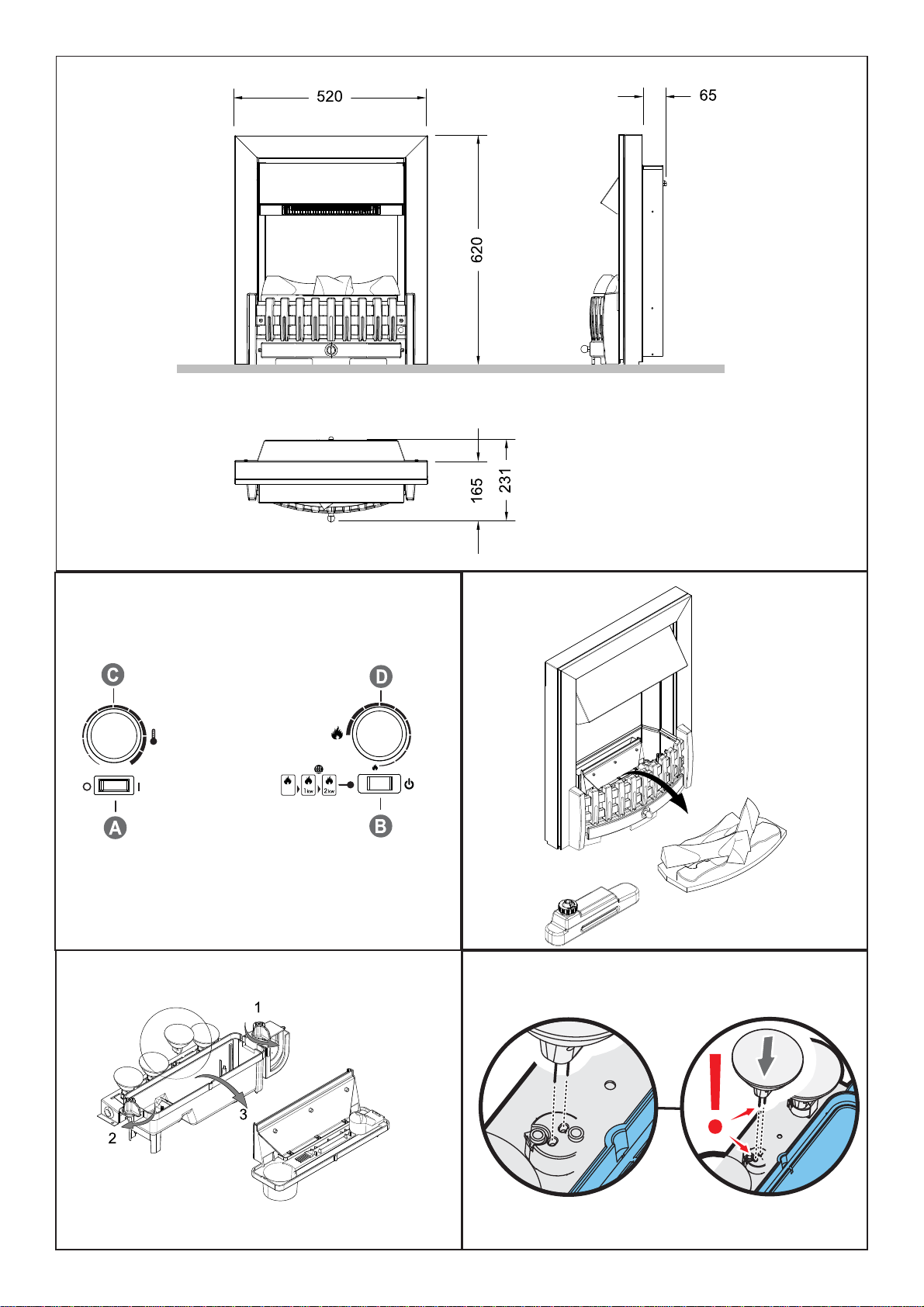
Fig.1
Fig.2
Fig.4
Fig.3
Fig.4a
Page 3
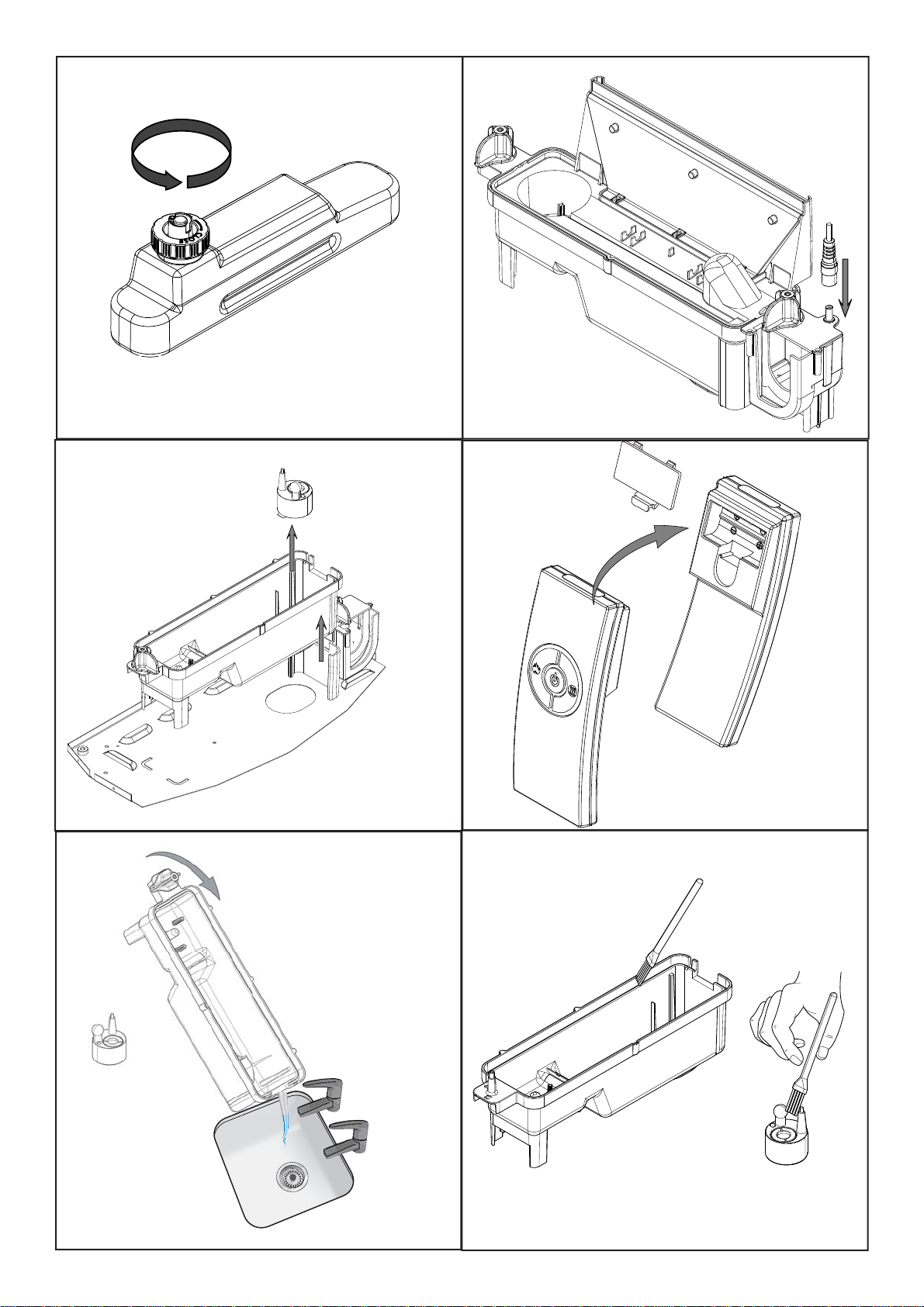
Fig.5
Fig.6
Fig.6a
Fig.8
Fig.7
Fig.9
Page 4
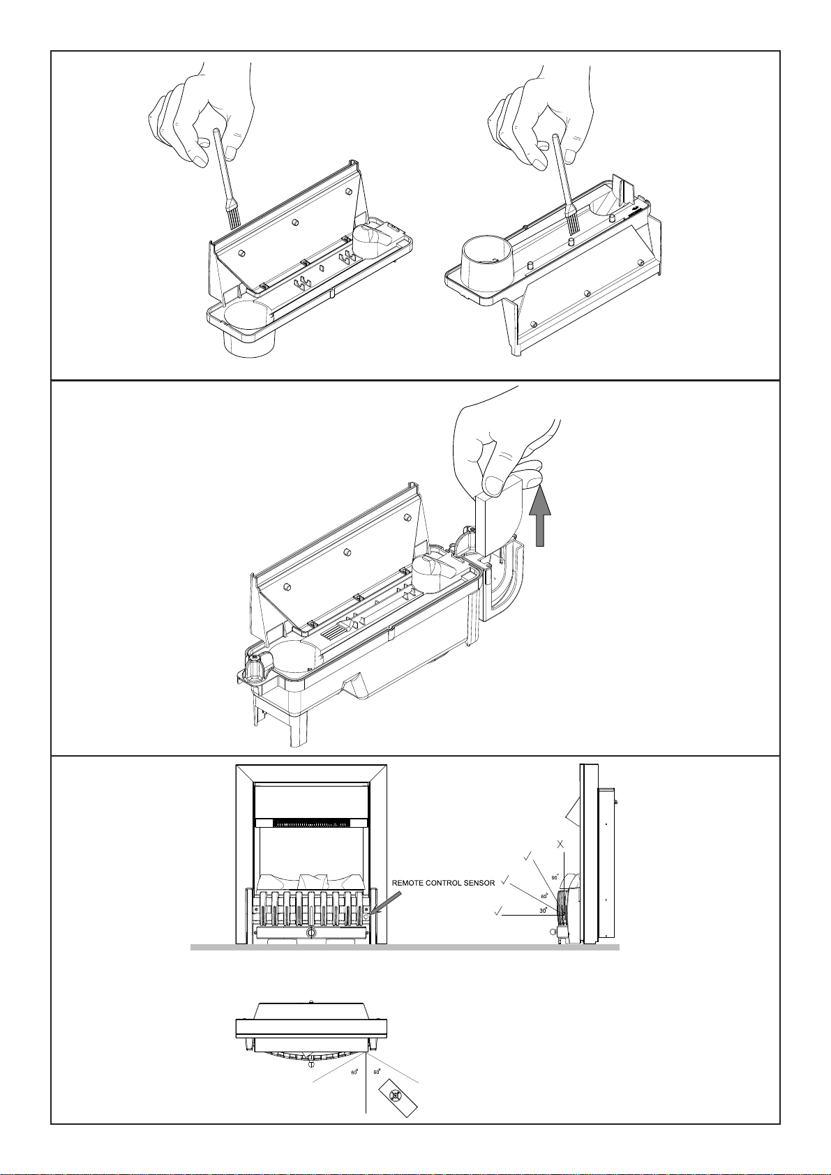
Fig.10
Fig.11
Fig.12
Page 5

GB .................................................................................................................................... 1
DE ..................................................................................................................................... 6
TR .................................................................................................................................. 11
RU .................................................................................................................................. 16
Page 6
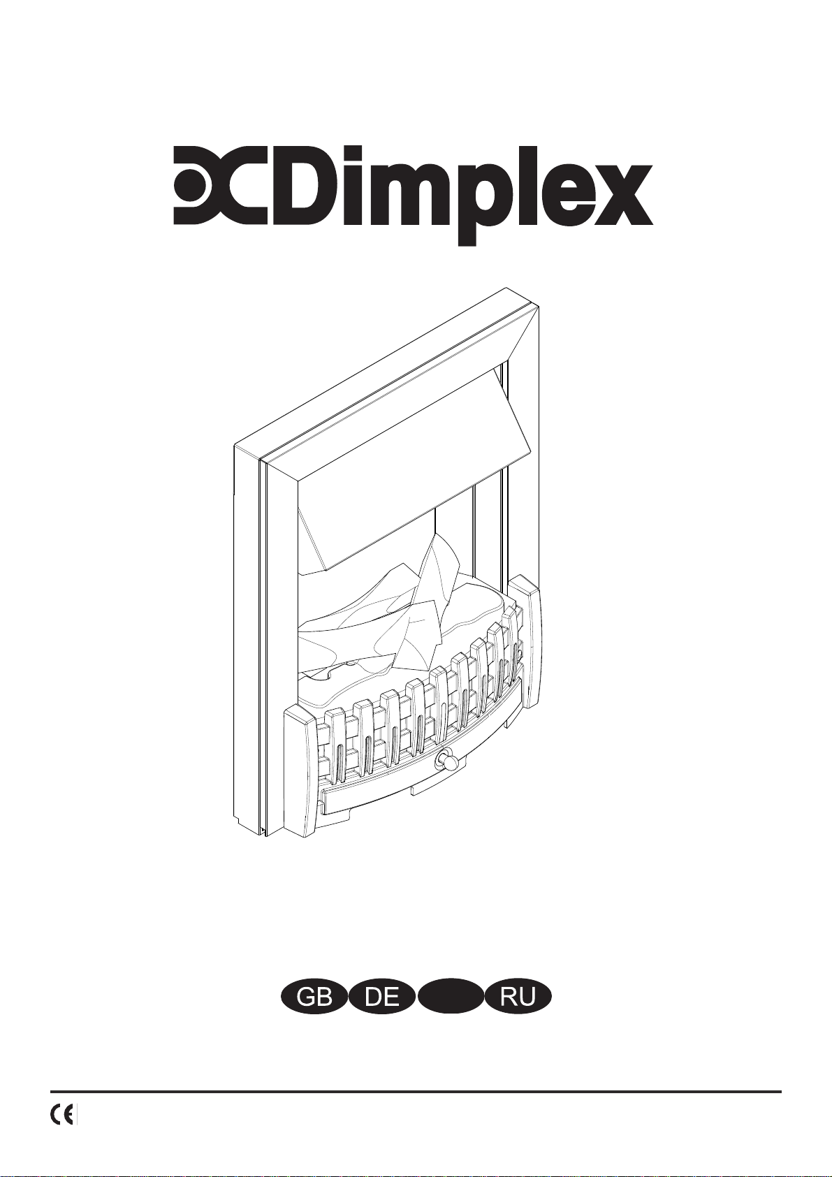
Dimplex Opti-myst Inset Fires
Model: DNV20AB, DNV20BR, DNV20BL, DNV20CH
IMPORTANT: THESE INSTRUCTIONS SHOULD BE READ CAREFULLY AND RETAINED FOR FUTURE REFERENCE
Important Safety Advice:
When using electrical appliances, basic precautions should always be followed to reduce the risk of fi re,
electrical shock and injury to persons, including the following:
If the appliance is damaged, check with the supplier before installation and operation.
Do not use outdoors.
Do not use in the immediate surroundings of a bath, shower or swimming pool.
Do not locate the heater immediately below a fi xed socket outlet or connection box.
This appliance is not intended for use by children or other persons without assistance or supervision if their
physical, sensory or mental capabilities prevent them from using it safely. Children should be supervised to
ensure that they do not play with the appliance.
Do not use this heater in series with a thermal control, a program controller, a timer or any other device that
switches on the heat automatically, since a fi re risk exists when the heater is accidentally covered or displaced.
Ensure that furniture, curtains or other combustible material are positioned no closer than 1 metre from the
heater.
In the event of a fault unplug the heater.
Unplug the heater when not required for long periods.
Although this heater complies with safety standards, we do not recommend its use on deep pile carpets or on
long hair type of rugs.
The appliance must be positioned so that the plug is accessible.
If the supply cord is damaged it must be replaced by the manufacturer or service agent or a similarly qualifi ed
person in order to avoid a hazard.
Keep the supply cord away from the front of the heater.
WARNING: In order to avoid overheating, do not cover the heater. Do not place material or garments on the
heater, or obstruct the air circulation around the heater.
The heater carries a DO NOT COVER warning.
General.
Unpack the heater carefully and retain the packaging for possible future use, in the event of moving or returning the re to
your supplier.
The re incorporates a ame e ect, which can be used with or without heating, so that the comforting e ect may be enjoyed
at any time of the year. Using the ame e ect on its own only requires little electricity.
The heater is designed for use inset into a 407mm (16”) or 457mm (18”) wide by 559mm (22”) high replace opening or
freestanding - see also section ‘Installation Instructions’.
A 2kw fan heater is discreetly positioned in the canopy of the re provides heating in cold weather. Switching allows half
or full heat. A distance of 1 metre (39”) must be maintained between the front of the heater and any surrounding furniture,
overhanging curtains or other obstrustions.
To reduce heat loss and to prevent any chimney up draft a ecting the operation of your inset re we recommend they the
chimney ue is sealed o .
Before connecting the heater check that the supply voltage is the same as that stated on the heater.
Please note: Used in an environment where background noise is very low, it may be possible to hear a sound which is related
to the operation of the ame e ect. This is normal and should not be a cause for concern.
Electrical connection.
WARNING – THIS APPLIANCE MUST BE EARTHED.
This heater must be used on an AC ~ supply only and the voltage marked on the heater must correspond to the supply voltage.
Before switching on, please read the safety warnings and operating instructions.
PLEASE RETAIN THIS USER’S GUIDE FOR FUTURE REFERENCE
Only use ltered tap water in this appliance.
Always ensure that the appliance is sitting on a level surface.
If you intend not using the appliance for longer than 2 weeks, drain the water from sump and water tank and dry the
sump.
Once installed, never move this appliance or lay on its back, without draining the water from sump and water tank.
The water tank, sump, sump lid, tank cap and air lters must be cleaned once every two weeks, particularly in hard
water areas.
The appliance should never be operated if the lamps are not working.
The lamps should be regularly inspected as described under ‘Maintenance’ and ‘Changing lamps’.
1
Page 7
Installation Instructions
Before installing this appliance in an existing chimnney, we recommend that;
1. You have your chimney cleaned by a competent chimney sweep.
2. You block o the chimney ue.
This procedure is important for the e cient operation of the heating unit and will also reduce heat loss up the chimney.
Installation.
Ensure that all packing items are removed (read any warning labels carefully).
Retain all packing for possible future use e.g. in the event of moving or returning the appliance to your supplier.
To install the appliance;
1. Clean the area where the re will be installed e.g remove ash residue from an existing replace.
2. Use the two adjustable supports at the rear of the appliance to ensure that the re is level.
3. Make sure the unit is switched OFF.
4. Hold the re by the sides of surround and gently manoeuvre into position. Plug the re into a 13amp/240 volt outlet. Ensure
that the supply cable is not trapped under the re such that it might cause it to be damaged.
Before using the manual controls rstly ll the water tank (See ‘Maintenance’, ‘Filling the water tank’).
Manual Controls.
The Opti-myst manual controls are located beneath the hinged canopy. Raise the canopy to access the controls. (See Fig.2 for
Manual Control lay out)
Switch ‘A’:- Controls the electricity supply to the Fire.
Note: This switch must be in the ‘ON’ ( I ) position for the Fire to operate either with or without heat.
Switch ‘B’:- Press
operate immediately it will take a further 30 seconds before the ame e ect starts.
Press again to give ame e ect and half heat. This will be indicated by two beeps.
Press again to give ame e ect and full heat. This will be indicated by three beeps.
Press again to return to ame e ect only. This will be indicated by one beep.
Press to put re in to standby mode. This will be indicated by one beep.
Control Knob ‘C’:- Controls the Thermostat setting.
Turning the control knob Anti Clockwise will decrease the temperature setting, turning the control knob Clockwise
will increase the temperature setting.
Control Knob ‘D’:- Controls the intensity of the ame e ect.
Turning the control knob Anti Clockwise increases the ame e ect, turning the control knob Clockwise will decrease
the ame e ect.
When the water in the tank and in the sump runs out the main lamps will go out. See instructions under ‘Maintenance’, ‘Filling
the water tank’. When this procedure is complete, the main lamps will illuminate but it will take 30 seconds before the ames
return.
Setting the Thermostat
Plug in and switch on the re to the full heat setting. Turn the Control Knob ‘C’ fully clockwise (max temperature setting) to
warm the room rapidly. When the room temperature has reached the desired level, turn the thermostat knob back slowly until
you hear the thermostat just click o . The heater will then maintain the room temperature at the chosen level.
Note: Should your heater fail to come on when the thermostat is at a low setting, this may be due to the room temperature
being higher then the thermostat setting
Thermal safety cut-out
A thermal safety cut-out is incorporated in the fan heater to prevent damage due to overheating. This can happen if the heat
outlet was restricted in any way or if the chimney ue has not been blocked o e ectively. If the cut-out operates, unplug the
heater from the socket outlet and allow approximately 10 minutes before reconnecting. Before switching the heater back on
remove any obstruction that may be restricting the heat outlet, then continue normal operation.
Caution: In order to avoid a hazard due to inadvertent resetting of the thermal cutout, this appliance must not be supplied
through an external switching device, such as a timer, or connected to a switch that is regularly switched on and o by the
utility.
once to turn on the ame e ect. This will be indicated by an audible beep. Although the main lights
2
Page 8

Tips for using your appliance.
1. With the ame setting on minimum the unit will use approximately 40ml of water per hour and will last 3 times as long than
when it is at maximum ame setting.
2. Do not tilt or move the re while there is water in the tank or sump.
3. Make sure that the re is on a level oor.
4. The ame control knob ‘D’ Fig.2 may be turned up or down to give a more realistic e ect.
5. Sometimes the ames appear more real when the ame control knob is turned down.
6. Give the ame generator some time to react to changes you may make on the ame control knob.
Maintenance
WARNING: ALWAYS DISCONNECT FROM THE POWER SUPPLY BEFORE BEGINNING ANY MAINTENANCE
Changing lamps.
If the smoke appears grey or colourless it may be that one or more lamps have failed.
You can check for lamp failure as follows.
1. Leaving the ame e ect on, lift out the fuelbed and water tank. (See Fig.3)
2. It should be possible to view the lamps with the nozzle (See Fig.4) in place and observe which one needs to be changed.
3. Put Switch ‘A’ in the ‘OFF’ position, and unplug the re from the mains.
4. Leave the appliance for 20 minutes to allow the lamps to cool down before removing them.
5. Remove the sump as described in the Cleaning Section.
6. Remove the defective lamp, by gently lifting vertically and disengaging the pins from the lamp holder, (See Fig.4 and 4a).
Replace with a Dimplex Opti-myst, 12V, 50W, Gu5.3 base, 8º beam angle, coloured lamp. (Purchased from www.dimplex.co.uk
under the section ‘After Sales Service’, details of how to purchase the lamps are contained therein.)
7. Carefully insert the two pins of the new lamp into the two holes in the lamp holder. Push rmly in place. (See Fig.4 and 4a).
8. Replace the sump, nozzle, water tank and fuelbed.
9. Switch on.
Filling the water tank.
When the water tank is empty, the ame and smoke e ect shuts o and you will hear 2 audible beeps, follow these steps.
1. Press Switch ‘A’ to (0) (See Fig.2)
2. Gently lift out the fuelbed and set aside carefully. (See Fig.3)
3. Remove the water tank by lifting upwards and outwards.
4. Place the water tank in sink and remove cap, Anti-clockwise to open. (See Fig.5)
5. Fill tank with ltered tap water only. This is necessary to prolong the life of the ame and smoke producing unit.
The water should be ltered through a conventional domestic water lter unit and the lter should be replaced regularly.
6. Screw the cap back on, do not overtighten.
7. Return the tank to the sump, with the tank cap facing down and the at side of the tank facing outward.
8. Gently place the fuelbed back into position.
9. Press Switch ‘A’ to ‘ON’ ( I ) position (See Fig.2)
Cleaning.
WARNING – ALWAYS DISCONNECT FROM THE POWER SUPPLY BEFORE CLEANING THE HEATER.
We recommend cleaning the following components once every 2 weeks, particularly in hard water areas:Water Tank, Sump, Nozzle, Tank cap and seal, Air lter.
For general cleaning use a soft clean duster – never use abrasive cleaners. To remove any accumulation of dust or u the soft
brush attachment of a vacuum cleaner should occasionally be used to clean the outlet grille of the fan heater.
Water tank
1. Remove water tank, as described earlier, put into sink and empty water.
2. Using the supplied brush gently rub the inside surfaces of the cap paying particular attention to the rubber ring in the outer
groove and the centre rubber seal.
3. Put a small quantity of washing up liquid into the tank, re t the cap and shake well, rinse out until all traces of washing up
liquid are gone.
4. Re ll with ltered tap water only, replace the cap, do not overtighten.
Sump
1. Press Switch ‘A’ to the ‘OFF’ (0) position
2. Gently lift out the fuelbed and place carefully on the ground. (See Fig.3)
3. Remove the water tank by lifting upwards.
4. Disconnect the electrical connector, located on the right side of the sump. (See Fig.6) .
5. Release the right sump locking tabs by turning 90º, this allows the sump to be lifted completely from its location.
(See Fig.6a)
6. Gently lift up the sump, taking care to keep level so as not to spill any water. Sit the assembly in the sink.
7. Release the left sump locking tabs by turning 90º, then lift o the Nozzle. (See Fig.4)
8. Lift out the transducer and carefully tilt, as shown, so that the liquid drains out of the sump. (See Fig.8)
3
Page 9
9. Put a small amount of washing up liquid into the sump, and using the supplied brush, gently clean all surfaces in the sump
and gently clean the transducer including the metal discs located in the top grooved surface. (See Fig.9)
10. When cleaned, thoroughly rinse the sump with clean water to remove all traces of washing up liquid.
11. Clean the outlet surface of the sump lid with the brush and ush out thoroughly with water. (See Fig.10)
12. Reverse the above steps to reassemble.
Air lter.
1. Press Switch ‘A’ to the ‘OFF’ (0) position (See Fig.2)
2. Gently lift out the fuelbed and place carefully on the ground. (See Fig.3)
3. Gently slide the air lter upwards out of its plastic holder. (See Fig.11)
4. Gently rinse with water in the sink and dry with fabric towel before returning.
5. Replace the lter making sure that the coarse black lter is facing the front of the re.
6. Replace the fuelbed.
7. Press Switch ‘A’ to the ‘ON’ ( I ) position (See Fig.2)
Remote Control Operation
On the control panel, Switch A (see Fig.2) must be in the ‘ON’ ( I ) position in order for the remote control to operate. There are 3
buttons on the remote control. (See Fig.7) To operate correctly the remote must be pointed towards the front of the grate. (See
Fig 12). The remote control functions are as follows:
Press once to turn on Flame e ect only.
This will be indicated by one beep.
Press once to turn on Half Heat and Flame E ect.
This will be indicated by two beeps.
Press again to turn on Full Heat and Flame E ect.
This will be indicated by three beeps.
Standby
This will be indicated by one beep.
Recycling.
For electrical products sold within the European Community. At the end of the electrical products useful life it should
not be disposed of with household waste. Please recycle where facilities exist. Check with your Local Authority or
retailer for recycling advice in your country.
After Sales Service.
Your product is guaranteed for one year from the date of purchase. Within this period, we undertake to repair or exchange this
product free of charge (excluding lamps & subject to availability) provided it has been installed and operated in accordance
with these instructions. Your rights under this guarantee are additional to your statutory rights, which in turn are not a ected
by this guarantee.
Should you require after sales information or assistance with this product please go to www.dimplex.co.uk where you will
nd our self help guide by clicking on “After Sales” or ring our help desk on 0845 600 5111 (UK) or 01 842 4833 (R. O. I.). Spare
parts are also available on the web site. Please retain your receipt as proof of purchase.
Patent / Patent Application
Products within the Optimyst range are protected by one or more of the following patents and patent applications:
Great Britain GB 2402206, GB 2460259, GB 2460453 , GB 2418014, GB 2465738, GB 2449925, GB 2465537 , GB 2455277 ,
GB1020534.2, GB1020537.5, GB1110987.3
United States US 7967690, US 2010299980, US 2011062250, US 2008028648, US 13/167,042
Russia RU2008140317
European EP 2029941, EP 2201301, EP 2315976, EP 1787063, EP07723217.1 , EP11170434.2, EP 11170435.9
China CN 101883953, CN 200980128666.2, CN 101057105, CN 101438104
Australia AU 2009248743, AU 2007224634
Canada CA 2725214, CA 2579444, CA 2645939
International Patent Application WO 2006027272
South Africa ZA 200808702
Mexico MX 2008011712
Korea KR 20080113235
Japan JP 2009529649
Brasil BR P10708894-9
India IN 4122/KOLNP/2008
New Zealand NZ 571900
4
Page 10

Troubleshooting
Symptom Cause Corrective Action
The ame e ect will
not start.
Mains plug is not plugged in.
Low water level.
Check plug is connected to wall socket correctly.
Check that the water tank is full and there is
water in the sump.
The ame e ect is too
low.
Unpleasant smell when
unit is used.
The ame e ect has
too much smoke.
Main lamps are not
working and there are
no ames or smoke.
Low voltage connector not connected properly.
(See Fig.6)
The Transducer Unit is not sitting correctly in
the sump
Flame e ect control knob is set too low.
(See Fig.2)
The Metal Disc in the transducer might be dirty
(See Fig.12)
The wire from the Transducer Unit is sitting over
the metal disc
Dirty or stale water.
Using un ltered tap water.
Flame e ect setting is too high. Turn the ame e ect Control knob C clockwise,
There is no water in the water tank Follow instructions under
Check that the connector is inserted correctly.
(See Fig.6)
Ensure the Transducer in sitting down into the
moulded recess in the sump
Increase level of ame by turning Control knob
‘D’ anti clockwise slowly. (See Fig.2)
Clean the Metal Disc with soft brush supplied.
(See Fig.12) See ‘Maintenance.’ for a step by step
procedure.
Direct the wire to the back of the sump and
make sure it sits into the side slot exiting the
sump.
Clean the unit as described under maintenance.
Use only ltered tap water.
about ¼ a turn, at a time. Give the ame
generator some time to adjust to the new
setting. (See Fig.2)
Maintenance, ‘Filling the water tank’.
Check the plug is connected to the wall socket
correctly and that Switch ‘A’ Fig. 2 is in the
‘ON’ ( I ) position.
5
Page 11

Dimplex Opti-myst Kamineinsätze
Modell: DNV20AB, DNV20BR, DNV20BL, DNV20CH
WICHTIG: DIESE ANLEITUNG FÜR ZUKÜNFTIGE NACHSCHLAGEZWECKE SORGFÄLTIG AUFBEWAHREN
Wichtige Sicherheitshinweise:
Beim Gebrauch von elektrischen Geräten sollten die grundlegenden Sicherheitsmaßnahmen immer befolgt
werden, um das Risiko von Brandbildung, elektrischem Schock und Verletzungen zu minimieren. Das schließt
Folgendes ein:
Wenn das Gerät beschädigt ist, wenden Sie sich vor einer Installation und Inbetriebnahme an den Händler.
Das Gerät darf nicht im Freien verwendet werden.
Nicht in unmittelbarer Nähe von Bädern, Duschen oder Schwimmbädern verwenden.
Das Heizgerät darf nicht unmittelbar unter einer Wandsteckdose oder einer Anschlussdose angebracht werden.
Dieses Gerät ist nicht für Kinder oder Personen ohne Hilfestellung oder Beaufsichtigung einer dritten Person
geeignet, wenn die sichere Benutzung des Geräts aufgrund der körperlichen oder geistigen Verfassung oder
wegen verminderter Wahrnehmung nicht möglich ist. Kinder sind zu beaufsichtigen, um sicherzustellen, dass
sie nicht mit dem Gerät spielen.
Das Heizgerät nicht zu einer Wärmeregelung, einer Programmsteuerung, einer Zeitschaltuhr oder einem anderen
Gerät in Reihe schalten, mit dem die Wärmequelle automatisch geschaltet wird. Bei versehentlicher Blockierung
oder Verstellung des Heizgeräts besteht Brandgefahr.
Möbel, Vorhänge und andere brennbare Stoffe dürfen sich nicht näher als 1 m vor dem Heizgerät befi nden.
Bei einem Fehler den Netzstecker des Heizgeräts ziehen.
Netzstecker des Heizgeräts ziehen, wenn es längere Zeit nicht benötigt wird.
Zwar erfüllt das Heizgerät die Sicherheitsstandards, jedoch raten wir von einer Benutzung auf hochfl origen
Fußbodenbelägen oder Teppichen ab.
Das Gerät muss so aufgestellt werden, dass der Netzstecker zugänglich ist.
Wenn das Netzkabel beschädigt ist, muss es vom Hersteller, einer Kundendienstvertretung oder einer
vergleichbar qualifi zierten Person ausgetauscht werden, um Gefahren zu vermeiden.
Das Stromversorgungskabel nicht in der Nähe der Vorderseite des Heizgeräts verlegen.
ACHTUNG: Um Überhitzungen zu vermeiden, darf das Heizgerät nicht zugedeckt werden. Keine Gegenstände
oder Kleidungsstücke auf das Heizgerät legen und die Luftzirkulation um das Heizgerät herum nicht behindern.
Das Heizgerät verfügt über ein Warnschild mit dem Hinweis NICHT BEDECKEN.
Allgemeines:
Das Heizgerät vorsichtig auspacken und die Verpackung für spätere Zwecke aufbewahren, z. B. für einen Umzug oder für die Rücksendung an
den Händler.
Dieser Kamineinsatz verfügt über einen Flammene ekt, der mit oder ohne Heizfunktion verwendet werden kann, damit in jeder Jahreszeit eine
gemütliche Stimmung erzeugt werden kann. Der Flammene ekt verbraucht bei ausgeschalteter Heizfunktion nur wenig elektrische Energie.
Das Heizgerät ist als Kamineinsatz für den Einbau in eine Kaminö nung mit 407 oder 457 x 559 mm (Breite x Höhe) oder frei stehend vorgesehen.
Beachten Sie dazu auch den Abschnitt „Installationsanweisungen“.
Ein diskret in die Esse des Kamineinsatz integriertes 2kw Heizgebläse sorgt bei kaltem Wetter für Wärme. Die Heizleistung des Gebläses kann
auf halb oder voll eingestellt werden. Zwischen der Vorderseite des Heizgeräts und Möbeln, darüber hängenden Gardinen oder anderen
Gegenständen muss ein Abstand von 1 Meter eingehalten werden.
Um Wärmeverluste und den negativen Ein uss eines eventuellen Kaminabzugs nach oben auf den Gerätebetrieb zu vermeiden, empfehlen wir
eine Blockierung des Kaminabzugs.
Vor dem Anschluss des elektrischen Kamins immer prüfen, ob die Versorgungsspannung mit den Angaben auf dem Heizgerät übereinstimmt.
Bitte beachten: Bei Verwendung in Umgebungen mit wenigen Hintergrundgeräuschen sind Betriebsgeräusche aufgrund des Flammene ekts
unter Umständen hörbar. Dies ist normal und kein Grund zur Beunruhigung.
Elektrischer Anschluss.
ACHTUNG – DIESES GERÄT MUSS GEERDET WERDEN.
Das Heizgerät darf nur an eine Wechselstromversorgung angeschlossen werden. Die auf dem Gerät angegebene Spannung muss mit der
Versorgungsspannung übereinstimmen. Lesen Sie vor dem Einschalten die Sicherheitshinweise und die Bedienungsanleitung durch.
DIE VORLIEGENDE ANLEITUNG BITTE ZU NACHSCHLAGEZWECKEN AUFBEWAHREN
In diesem Gerät darf nur ge ltertes Leitungswasser verwendet werden.
Immer darauf achten, dass das Gerät auf ebenem Untergrund steht.
Falls das Gerät länger als 2 Wochen nicht benutzt wird, muss das Wasser aus dem Sumpf und Wassertank abgelassen und der Sumpf
getrocknet werden.
Nach der Installation darf dieses Gerät nicht transportiert oder auf die Rückseite gelegt werden, ohne zuvor das Wasser aus dem Sumpf
und Wassertank abzulassen.
Einmal alle zwei Wochen müssen Wassertank, Sumpf, Sumpfdeckel, Tankdeckel und die Luft lter gereinigt werden,, insbesondere in
Regionen mit hartem Wasser.
Das Gerät darf auf keinen Fall in Betrieb gesetzt werden, wenn die Lampen nicht funktionieren.
Die Lampen sind regelmäßig zu überprüfen, siehe „Wartung“ und „Lampenwechsel“.
6
Page 12

Installationsanleitung
Vor der Installation dieses Geräts in einen bestehenden Kamin sind folgende Punkte empfehlenswert:
1. Lassen Sie Ihren Kaminabzug von einem quali zierten Kaminkehrer reinigen.
2. Blockieren Sie den Rauchabzug.
Dies ist nicht nur für einen e zienten Betrieb des Heizgeräts wichtig, sondern dadurch werden auch Wärmeverluste über den Kaminabzug
verhindert.
Installation
Das Verpackungsmaterial von sämtlichen Teilen entfernen (eventuelle Aufkleber mit Warnhinweisen beachten).
Das Verpackungsmaterial für spätere Zwecke aufbewahren, z. B. für einen Umzug oder für die Rücksendung an den Händler.
Installation des Geräts
1. Den Installationsbereich des Einsatzes reinigen, z.B. Ascherückstände beseitigen.
2. Die beiden verstellbaren Standfüße auf der Rückseite des Geräts verwenden, um das Heizgerät auszurichten.
3. Vergewissern Sie sich, dass das Gerät auf OFF (Aus) geschaltet ist.
4. Den Kamineinsatz seitlich an der Umrandung festhalten und vorsichtig in Einbaulage manövrieren. Den Kamineinsatz an eine Steckdose
anschließen, die mit 13 A/240 V versorgt wird. Sicherstellen, dass das Netzkabel nicht unter dem Kamineinsatz verklemmt ist, da es sonst
beschädigt werden kann.
Vor dem Betätigen der manuellen Bedienelemente muss zuerst der Wassertank befüllt werden (siehe „Wartung“ und „Wassertank
au üllen“).
Manuelle Bedienelemente
Hinter der aufklappbaren Esse sind die manuellen Bedienelemente des Opti-myst angeordnet. Klappen Sie die Esse nach oben, um die
Bedienelemente betätigen zu können. (Anordnung der manuellen Bedienelemente, siehe Abb. 2)
Schalter „A“: Regelt die Energieversorgung zum Kamineinsatz.
Hinweis: Dieser Schalter muss auf „ON“ ( I ) stehen, um das Heizgerät mit oder ohne Heizfunktion zu betreiben.
Schalter „B“:
Hauptleuchten sofort, allerdings dauert die Aktivierung des Flammene ekts weitere 30 Sekunden.
Erneut drücken, um Flammene ekt und die halbe Heizleistung einzuschalten. Dies wird durch Ausgabe von zwei Pieptönen signalisiert.
Erneut drücken, um Flammene ekt und die volle Heizleistung einzuschalten. Dies wird durch Ausgabe von drei Pieptönen signalisiert.
Erneut drücken, um wieder zum Flammene ekt ohne Wärmeabgabe zurückzuschalten. Dies wird durch Ausgabe eines Pieptons signalisiert.
Drehregler „C“: Dient zum Einstellen des Thermostats.
Durch Drehen des Reglers nach links wird eine niedrigere Temperatur und nach rechts eine höhere Temperatur am Thermostat
Drehregler „D“: Stellt die Stärke des Flammene ekts ein.
Durch Drehen des Reglers nach links wird der Flammene ekt gesteigert und nach rechts wird er reduziert.
Wenn der Tank und der Sumpf leer sind, gehen die Hauptleuchten aus. Befolgen Sie die Anweisungen unter „Wartung“, „Wassertank au üllen“. Im
Anschluss daran leuchten die Hauptleuchten zwar wieder, jedoch dauert es weitere 30 Sekunden, bis die Flammen wieder lodern.
Thermostat einstellen
Netzstecker des Heizgeräts einstecken und auf volle Heizleistung einstellen. Drehregler „C“ ganz nach rechts drehen (maximale
Temperatureinstellung), um den Raum rasch zu erwärmen. Wenn die gewünschte Raumtemperatur erreicht ist, drehen Sie den Thermostatknopf
langsam gegen den Uhrzeigersinn, bis ein Klick zu hören ist. Das Heizgerät hält dann die Raumtemperatur auf dem eingestellten Wert.
Hinweis: Wenn sich das Heizgerät bei niedrig eingestelltem Thermostat nicht einschaltet, liegt dies möglicherweise daran, dass die
Raumtemperatur höher als die Thermostateinstellung ist.
Sicherheitsabschaltung
Um einen Defekt durch Überhitzung zu vermeiden, ist das Heizgebläse des Geräts mit einer Sicherheitsabschaltung ausgestattet. Der Fall
kann eintreten, wenn der Wärmeauslass auf bestimmte Weise eingeschränkt oder der Kaminabzug nicht nachhaltig blockiert wurde. Falls die
Sicherheitsabschaltung einsetzt, ziehen Sie den Netzstecker des Heizgeräts aus der Steckdose, und warten Sie 10 Minuten, bevor Sie das Gerät
wieder anschließen. Vor dem erneuten Einschalten des Heizgeräts sollten Blockaden beseitigt werden, durch die die Wärmeabgabe des Geräts
verhindert wird. Anschließend kann der normale Betrieb wieder fortgesetzt werden.
Vorsicht: Zur Vermeidung von Gefahren durch versehentliches Rückstellen der Sicherheitsabschaltung bei Überhitzung darf dieses Gerät nicht
über eine externe Schaltvorrichtung wie etwa eine Zeitschaltuhr mit Energie versorgt oder mit einem Schalter verbunden werden, der über die
Vorrichtung regelmäßig ein- und ausgeschaltet wird.
einmal drücken, um den Flammene ekt einzuschalten. Dies wird durch Ausgabe eines Pieptons signalisiert. Zwar reagieren die
Drücken, um den Kamineinsatz auf Standby zu schalten. Dies wird durch Ausgabe eines Pieptons signalisiert.
eingestellt.
7
Page 13

Tipps für die Gerätenutzung
1. Bei kleinster Flammeneinstellung verbraucht das Gerät etwa 40 ml Wasser pro Stunde und lässt sich dadurch 3 mal länger als bei maximaler
Flammenhöhe betreiben.
2. Wenn sich Wasser im Tank oder Sumpf be ndet, darf der Kamineinsatz nicht gekippt oder versetzt werden.
3. Der Kamineinsatz muss auf einem ebenem Untergrund stehen.
4. Für einen realistischen Flammene ekt kann der Flammenregler „D“ (Abb. 2) höher oder niedriger eingestellt werden.
5. Die Flammen erscheinen manchmal realistischer, wenn der Flammenregler kleiner eingestellt wird.
6. Warten Sie einen Moment, bis der Flammengenerator auf die veränderte Flammenreglereinstellung reagiert hat.
Wartung
ACHTUNG: VOR BEGINN VON WARTUNGSARBEITEN IMMER DEN NETZSTECKER ZIEHEN
Lampenwechsel
Wenn der Rauch grau oder farblos erscheint, sind unter Umständen eine oder mehrere Lampen defekt.
Die Lampen können Sie folgendermaßen auf Funktion prüfen:
1. Das Feuerbett und den Wassertank bei eingeschaltetem Flammene ekt herausheben. (Siehe Abb. 3)
2.
Es sollte möglich sein, die Lampen mit angebrachter Düse (siehe Abb. 4) zu betrachten, um festzustellen, welche Lampe ausgetauscht werden muss.
3. Stellen Sie Schalter „A“ auf Position „OFF“ (AUS) und ziehen Sie den Netzstecker des Kamineinsatzes aus der Steckdose.
4. Lassen Sie das Gerät 20 Minuten lang ausgeschaltet, damit sich die Lampen vor dem Ausbau abkühlen können.
5. Bauen Sie den Sumpf aus, wie im Abschnitt „Reinigung“ erläutert.
6. Ziehen Sie die defekte Lampe mit den Kontaktstiften vorsichtig nach oben aus dem Lampensockel heraus (siehe Abb. 4 und 4a). Bauen Sie als
Ersatzlampe eine Dimplex Opti-myst Farblampe für 12 V, 50 W, Sockel Gu5.3 mit 8º Abstrahlwinkel ein. (Bestellung über www.dimplex.co.uk unter
„Kundenservice“. Dort wird auch die Bestellung der Lampen erläutert.)
7. Führen Sie die beiden Kontaktstifte der neuen Lampe in die beiden Ö nungen des Lampensockels ein und schieben Sie sie bis zum Anschlag
hinein. (Siehe Abb. 4 und 4a.)
8. Sumpf, Düse, Wassertank und Feuerbett wieder anbringen.
9. Schalten Sie das Gerät ein.
Wassertank au üllen
Wenn der Wassertank leer ist, schaltet sich der Flammen- und Rauche ekt ab und es ertönen 2 akustische Warnsignale.
1. Schalter „A“ auf (0) stellen (Siehe Abb. 2)
2. Feuerbett vorsichtig herausheben und beiseite legen. (Siehe Abb. 3)
3. Den Wassertank nach oben aus dem Gerät herausheben.
4. Den Wassertank in ein Waschbecken legen und den Tankdeckel gegen den Uhrzeigersinn abschrauben. (Siehe Abb. 5)
5. Tank nur mit ge ltertem Leitungswasser füllen. Dadurch verlängert sich die Lebensdauer des Rauch- und Flammengenerators.
Zum Filtern des Wassers sollte ein handelsüblicher Wasser lter benutzt werden, der regelmäßig auszutauschen ist.
6. Den Deckel wieder festschrauben, aber nicht überdrehen.
7. Den Tank wieder in den Sumpf einsetzen. Der Tankdeckel muss dabei nach unten und die ache Tankseite nach außen zeigen.
8. Feuerbett vorsichtig wieder einsetzen.
9. Schalter „A“ auf „ON“ ( I ) stellen (Siehe Abb. 2)
Reinigung
ACHTUNG – VOR DEM REINIGEN DES HEIZGERÄTES IMMER DEN NETZSTECKER ZIEHEN.
Bei folgenden Teilen empfehlen wir eine regelmäßige Reinigung alle 2 Wochen, insbesondere in Regionen mit hartem Wasser:
Wassertank, Sumpf, Düse,Tankdeckel und -dichtung, Luft lter.
Zum Reinigen allgemein immer ein weiches, sauberes Staubtuch benutzen, auf keinen Fall Scheuermittel verwenden. Um angesammelten Staub
oder Flusen zu entfernen, kann gelegentlich ein Staubsauger mit weichem Bürstenaufsatz zum Reinigen des Auslassgitters des Lüftergebläses
verwendet werden.
Wassertank
1. Den Tank - wie zuvor erläutert - ausbauen, in ein Waschbecken legen und das Wasser ablassen.
2. Mit der beigefügten Bürste die Innen ächen des Deckels sanft abbürsten. Dabei besonders den Gummiring in der Außennut und die
Gummidichtung in der Mitte sauber bürsten.
3. Eine sparsame Menge Spülmittel in den Tank füllen, den Deckel festschrauben und gut schütteln. Das Spülmittel komplett wieder ausspülen,
bis davon keine Spuren im Abwasser mehr zu sehen sind.
4. Ausschließlich mit ge ltertem Leitungswasser au üllen, den Deckel wieder anbringen und nicht überdrehen.
Sumpf
1. Schalter „A“ auf „OFF“ (0) stellen
2. Feuerbett vorsichtig herausheben und auf den Boden legen. (Siehe Abb. 3)
3. Den Wassertank nach oben herausheben.
4. Den Stecker aus der Anschlussbuchse auf der linken Seite des Sumpfs ziehen. (Siehe Abb. 6).
5. Die Sicherungskrallen am rechten Sumpfs um 90° drehen. Der Sumpf kann nun komplett aus der Einbaulage herausgehoben werden. (Siehe
Abb. 6a)
6. Den Sumpf vorsichtig und möglichst waagerecht herausheben, damit kein Wasser verschüttet wird. Das gesamte Bauteil in ein Waschbecken
stellen.
7. Die beiden Sicherungskrallen am linken Sumpf um 90° drehen und die Düse abnehmen. (Siehe Abb. 4)
8
Page 14

8. Den Wandler herausheben und vorsichtig seitlich kippen, damit die Flüssigkeit aus dem Sumpf ablaufen kann. (Siehe Abb. 8)
9. Etwas Spülmittel in den Sumpf füllen und mit der beigefügten Bürste sämtliche Flächen im Sumpf und den Wandler sanft reinigen, auch die
Metallscheiben, die in der Nut auf der Oberseite verlegt ist. (Siehe Abb. 9)
10. Nach dem Reinigen den Sumpf mit klarem Wasser gründlich ausspülen, um alle Spülmittelrückstände zu beseitigen.
11. Die Auslass äche am Sumpfdeckel mit der Bürste säubern und mit Wasser gründlich spülen. (Siehe Abb. 10)
12. Beim Zusammenbau die obigen Schritte in umgekehrter Reihenfolge befolgen.
Luft lter
1. Schalter „A“ auf „OFF“ (0) stellen (Siehe Abb. 2)
2. Feuerbett vorsichtig herausheben und auf den Boden legen. (Siehe Abb. 3)
3. Den Luft lter vorsichtig nach oben aus seiner Kunststo halterung herausziehen. (Siehe Abb. 11)
4. Vorsichtig mit Wasser im Waschbecken ausspülen und vor dem Einsetzen mit einem Handtuch abtrocknen.
5. Den Filter wieder einsetzen, dabei darauf achten, dass der grobe schwarze Filter in Richtung Vorderseite des Kamineinsatzes zeigt.
6. Das Feuerbett wieder einsetzen.
7. Schalter „A“ auf „ON“ ( I ) stellen (Siehe Abb. 2)
Betrieb über die Fernbedienung
Am Bedienfeld muss Schalter A (siehe Abb. 2) auf „ON“ ( I ) stehen, damit das Gerät über die Fernbedienung gesteuert werden kann. Auf der
Fernbedienung be nden sich 3 Tasten. (siehe Abb. 7) Zum korrekten Betrieb muss die Fernbedienung nach vorne in Richtung Kaminrost gehalten
werden. (Siehe Abb. 12). Die Fernbedienung besitzt folgende Funktionen:
Einmal drücken, um nur den Flammene ekt einzuschalten.
Dies wird durch Ausgabe eines Pieptons signalisiert.
Einmal drücken, um die halbe Heizleistung und den Flammene ekt einzuschalten.
Dies wird durch Ausgabe von zwei Pieptönen signalisiert.
Noch einmal drücken, um die volle Heizleistung und den Flammene ekt einzuschalten.
Dies wird durch Ausgabe von drei Pieptönen signalisiert.
Standby
Dies wird durch Ausgabe eines Pieptons signalisiert.
Wiederverwertung
Für die Entsorgung dieses Heizgerätes gelten entsprechende Richtlinien für die Entsorgung von Elektroprodukten innerhalb der
europäischen Gemeinschaft. Elektrogeräte dürfen am Ende ihrer Nutzungsdauer nicht im regulären Haushaltsmüll entsorgt werden.
Sie müssen einer entsprechenden Recycling-Sammelstelle zugeführt werden. Entsprechende Hinweise zu Annahmestellen erhalten
Sie bei der zuständigen lokalen Behörde oder Ihrem Fachhändler.
Kundenservice
Für dieses Produkt gilt eine Garantie von einem Jahr ab Kaufdatum. Innerhalb dieses Zeitraums verp ichten wir uns, Reparaturen oder einen
Gerätetausch kostenlos durchzuführen (ausgenommen Lampen und abhängig von der Verfügbarkeit), sofern gewährleistet ist, dass die
vorliegenden Anweisungen bei der Installation und Bedienung beachtet wurden. Ihre Rechte gemäß dieser Gewährleistung gelten zusätzlich
zu Ihren gesetzlichen Rechten, die von dieser Gewährleistung unberührt bleiben.
Wenn Sie Kundendienstinformationen oder Hilfe zu diesem Produkt benötigen, besuchen Sie bitte die Website www.dimplex.co.uk. Unter
dem Punkt „After Sales“ (Kundendienst) nden Sie unsere Lösungsvorschläge im Falle eines Problems. Sie können auch unsere Hotline unter
0845 600 5111 (GB) oder 01 842 4833 (Irland) anrufen. Ersatzteile nden Sie auch auf der Website. Bewahren Sie Ihre Quittung bitte als
Kaufnachweis auf.
Patent / Patentanmeldung
Produkte im Optimyst-Sortiment sind durch eines bzw. mehrere der nachfolgend aufgeführten Patente urheberrechtlich geschützt:
Großbritannien GB 2402206, GB 2460259, GB 2460453 , GB 2418014, GB 2465738, GB 2449925, GB 2465537 , GB 2455277 , GB1020534.2,
GB1020537.5, GB1110987.3
USA US 7967690, US 2010299980, US 2011062250, US 2008028648, US 13/167,042
Russland RU2008140317
Europa EP 2029941, EP 2201301, EP 2315976, EP 1787063, EP07723217.1 , EP11170434.2, EP 11170435.9
China CN 101883953, CN 200980128666.2, CN 101057105, CN 101438104
Australien AU 2009248743, AU 2007224634
Kanada CA 2725214, CA 2579444, CA 2645939
Internationale Patentanmeldung WO 2006027272
Südafrika ZA 200808702
Mexiko MX 2008011712
Korea KR 20080113235
Japan JP 2009529649
Brasilien BR P10708894-9
Indien IN 4122/KOLNP/2008
Neuseeland NZ 571900
9
Page 15

Fehlerdiagnose
Symptom Ursache Abhilfe
Der Flammene ekt
lässt sich nicht
einschalten.
Netzstecker ist nicht angeschlossen.
Wenig Wasser.
Prüfen Sie, ob der Netzstecker richtig an die
Steckdose angeschlossen ist.
Prüfen Sie, ob der Wassertank gefüllt ist, und ob
sich Wasser im Sumpf be ndet.
Der Flammene ekt
arbeitet zu niedrig.
Unangenehmer Geruch
während des Betriebs.
Der Flammene ekt
stößt zu viel Rauch aus.
Die Hauptlampen
leuchten nicht, und es
sind weder Flammen
noch Rauch zu sehen.
Der Niederspannungsstecker ist nicht richtig
angeschlossen. (Siehe Abb. 6)
Die Wandlereinheit sitzt nicht richtig im Sumpf
Der Drehregler für den Flammene ekt ist zu
niedrig eingestellt. (Siehe Abb. 2)
Die Metallscheibe im Wandler ist evtl.
verschmutzt (siehe Abb. 12)
Die Leitung von der Wandlereinheit liegt über
der Metallscheibe
Verschmutztes oder abgestandenes Wasser.
Es wird unge ltertes Leitungswasser benutzt.
Der Flammene ekt ist zu stark eingestellt. Den Drehregler „C“ für den Flammene ekt
Es ist kein Wasser im Tank Befolgen Sie die Anweisungen unter
Prüfen Sie, ob der Stecker korrekt angeschlossen
ist. (Siehe Abb. 6)
Sorgen Sie dafür, dass der Wandler richtig in der
geformten Aussparung im Sumpf sitzt
Den Drehregler „D“ langsam nach links drehen,
um die Flammen höher zu stellen. (Siehe Abb. 2)
Die Metallscheibe mit der beigefügten weichen
Bürste reinigen. (Siehe Abb. 12). Die schrittweise
gegliederten Anweisungen nden Sie im
Abschnitt „War tung“.
Die Leitung zur Rückseite des Sumpfs führen
und darauf achten, dass sie im seitlichen Schlitz
aus dem Sumpf austritt.
Das Gerät wie im Wartungsabschnitt erläutert
reinigen.
Nur ge ltertes Leitungswasser benutzen.
langsam jeweils ¼ nach rechts drehen. Warten
Sie etwas, bis der Flammengenerator auf die
neue Einstellung reagieren kann. (Siehe Abb. 2)
„Wartung“ „Wassertank au üllen“.
Prüfen Sie, ob der Netzstecker richtig an die
Steckdose angeschlossen ist und Schalter „A“
(Abb. 2) auf „ON“ ( I ) steht.
10
Page 16

Dimplex Opti-myst Gömme Şömineler
TR
Model: DNV20AB, DNV20BR, DNV20BL, DNV20CH
ÖNEMLİ: BU TALİMATLAR DİKKATLİCE OKUNMALI VE İLERİDE BAŞVURMAK ÜZERE SAKLANMALIDIR
Önemli Güvenlik Tavsiyesi:
Elektrikli cihaz kullanırken, yangın, elektrik çarpması ve kişisel yaralanma riskini azaltmak için aşağıdakileri
içeren temel uyarılara dikkat edilmelidir:
Cihaz hasar görmüşse, montaj ve kullanımdan önce tedarikçiye kontrol ettirin.
Açık havada kullanmayın.
Banyo, duş veya yüzme havuzunun çok yakınında kullanmayın.
Isıtıcıyı, sabit priz veya bağlantı kutusunun hemen altına yerleştirmeyin.
Bu cihaz çocukların veya fi ziksel, algısal ya da zihinsel açıdan tek başlarına kullanmaları güvenli olmayan
kişilerin yardım almadan kullanmaları için uygun değildir. Çocukların cihazla oynamadıklarından emin olmak için
gözetim altında tutulmaları gerekir.
Isıtıcının yanlışl
bulunmasından ötürü bu ısıtıcıyı bir termal kontrol, program kontrolörü, zamanlayıcı veya ısıtıcıyı otomatik
olarak açan başka bir cihazla birlikte kullanmayın.
Mobilya, perde veya diğer yanabilecek malzemelerin ısıtıcıya 1 metreden daha yakın olmamasına dikkat edin.
Arıza durumunda, ısıtıcının fi şini çekin.
Uzun süre kullanılması gerekmediğinde ısıtıcının fi şini çekin.
Her ne kadar bu ısıtıcı güvenlik standartlarına uygun olsa da, uzun tüylü halılar veya kilimler üzerinde
kullanılmasını tavsiye etmeyiz.
Cihaz, fi şe erişilebilecek şekilde yerleştirilmelidir.
Elektrik kablosu hasar görürse, tehlikeli bir durumdan kaçınmak için üretici veya servis temsilcisi ya da benzer
nitelikteki bir kişi tarafından değiştirilmelidir.
Elektrik kablosunu ısıtıcının ön kısmından uzak tutun.
UYARI: Aşırı ısınmayı önlemek için, ısıtıcının üzerini örtmeyin. Isıtıcı üzerine giyecek veya malzeme
yerleştirmeyin veya ısıtıcı çevresindeki hava sirkülasyonunu engellemeyin.
ıkla üzerinin kapatılması veya yerinden hareket ettirilmesi durumunda yangın riski
Isıtıcının üzerinde bir ÜZERİNİ ÖRTMEYİN uyarısı vardır.
Genel Bilgiler.
Isıtıcıyı dikkatle ambalajından çıkartın ve ambalajı taşınma ya da ısıtıcıyı iade etme gibi gelecekteki olası kullanımlar için saklayın.
Şömine, ısıtma ile veya ısıtma yapmadan kullanılabilecek bir alev efektine sahiptir, bu sayede rahatlatıcı etkisinin key yıl boyunca
sürülebilir. Alev efektinin tek başına kullanılması çok az elektrik tüketir.
Isıtıcı 407 mm (16”) veya 457 mm (18”) genişlikte, 559 mm (22”) yükseklikte şömine yuvasında kullanım veya kendi ayakları
üzerinde kullanım için tasarlanmıştır - ayrıca bkz ‘Montaj Talimatları’.
Şömine kanopisine tedbirli biçimde yerleştirilmiş olan 2 kW fan soğuk havalarda ısıtma sağlar. Çalıştırma yarım veya tam ısıtmaya
izin verir. Isıtıcının ön tarafı ile çevredeki mobilyalar, asılı perdeler veya diğer nesneler arasında 1 metre (39”) mesafe korunmalıdır.
Isı kaybını azaltmak ve şöminenin çalışmasını etkileyen herhangi bir baca yukarı çekişini önlemek için, şömine bacasının
yalıtılmasını tavsiye ederiz.
Isıtıcıyı prize takmadan önce besleme voltajının ısıtıcıda belirtilenle aynı olduğundan emin olun.
Lütfen dikkat: Arka plan gürültüsünün çok düşük olduğu ortamlarda kullanıldığında, alev efekti ile ilgili bir ses duyulması
mümkündür. Bu normaldir ve kaygı uyandırmamalıdır.
Elektrik bağlantısı.
UYARI – BU CİHAZ TOPRAKLANMALIDIR.
Bu ısıtıcı sadece AC voltaj ile kullanılmalı ve ısıtıcı üzerindeki voltaj şebeke voltajı ile aynı olmalıdır. Çalıştırmadan önce, güvenlik
uyarılarını ve çalıştırma talimatlarını okuyun.
GELECEKTE KULLANMAK ÜZERE LÜTFEN BU KULLANICI KILAVUZUNU SAKLAYIN
Bu cihazda sadece ltrelenmiş musluk suyu kullanın.
Cihazın daima düz bir yüzey üzerinde durduğundan emin olun.
Cihazı 2 haftadan daha uzun süreyle kullanmayı düşünmüyorsanız, suyu hazneden ve su deposundan boşaltın ve hazneyi
kurutun.
Monte edildikten sonra, suyu hazneden ve su deposundan boşaltmadan önce bu cihazı asla hareket ettirmeyin veya
arkasına doğru yatırmayın.
Su deposu, hazne, hazne kapağı, depo kapağı ve hava ltreleri her iki haftada bir özellikle su sertliğinin yüksek olduğu
yerlerde temizlenmelidir.
Cihaz, lambalar çalışır durumda değilse asla kullanılmamalıdır.
Lambalar düzenli olarak ‘Bakım’ ve ‘Lambaların değiştirilmesi bölümlerinde açıklandığı şekilde kontrol edilmelidir’.
11
Page 17

Montaj Talimatları
Mevcut bacaya bu cihazı monte etmeden önce, şunları yapmanızı öneririz;
1. Bacanızı yetkili bir baca temizleyicisine temizlettirin.
2. Baca deliğini tıkayın.
Bu işlem, ısıtma ünitesinin verimli çalışması için önemlidir ve ayrıca bacaya doğru olabilecek ısı kaybını da azaltır.
Montaj.
Tüm ambalaj malzemelerinin çıkartıldığından emin olun (her türlü uyarı etiketini dikkatlice okuyun).
Cihazı taşımanız veya tedarikçinize iade etmeniz durumuna karşı tüm ambalajı ileride kullanmak üzere saklayın.
Cihazı monte etmek için;
1. Şöminenin monte edileceği bölgeyi temizleyin (önceki şömineden kalan kül kalıntılarını giderin).
2. Şöminenin düz olmasını sağlamak için cihazın arkasındaki iki ayarlanabilir desteği kullanın.
3. Ünitenin KAPALI olduğundan emin olun.
4. Dekorun yan tara arından şömineyi kavrayın ve yavaşça yerine doğru yerleştirin. Şömineyi 13 amper/240 volt prize takın.
Elektrik kablosunun, zarar görecek şekilde şöminenin altında sıkışmamasına dikkat edin.
Manuel kumandaları kullanmadan önce su deposunu doldurun (Bkz. ‘Bakım’, ‘Su deposunun doldurulması’).
Manuel Kumandalar.
Opti-myst manuel kumandaları menteşeli kanopi altındadır. Kumandalara erişmek için kanopiyi kaldırın. (Manuel Kumanda
yerleşimi için bkz. Şekil 2)
Anahtar ‘A’:- Şömineye gelen elektrik beslemesini kontrol eder.
Not: Bu anahtarın, Şöminenin ısı vererek veya ısı vermeden çalışması için ‘ON’ (Açık) ( I ) konumunda bulunması gerekir.
Anahtar ‘B’:- Alev etkisini açmak için
alev etkisinin başlaması ilave bir 30 saniye daha alır.
Alev etkisini ve yarım ısıyı vermek için tuşuna tekrar basın. Bu durum iki bip sesi ile bildirilir.
Alev etkisini ve tam ısıyı vermek için tuşuna tekrar basın. Bu durum üç bip sesi ile bildirilir.
Sadece alev etkisine geri dönmek için tuşuna tekrar basın. Bu durum bir bip sesi ile bildirilir.
Şömineyi bekleme moduna almak için tuşuna basın. Bu durum bir bip sesi ile bildirilir.
Kumanda Düğmesi ‘C’:- Termostat ayarını kontrol eder.
Kumanda düğmesinin Saatin Ters Yönünde çevrilmesi sıcaklık ayarını düşürür, kumanda düğmesinin Saat Yönünde
çevrilmesi sıcaklık ayarını yükseltir.
Kumanda Düğmesi ‘D’:- Alev etkisinin yoğunluğunu kontrol eder.
Kumanda düğmesinin Saatin Ters Yönünde çevrilmesi alev etkisini artırır, kumanda düğmesinin Saat Yönünde çevrilmesi
alev etkisini azaltır.
Depo ve haznedeki su bittiğinde ana lambalar sönecektir. Şu bölümlerdeki talimatlara bakın: ‘Bakım’, ‘Su deposunun
doldurulması’. Bu işlem tamamlandığında, ana lambalar yanar ancak alevlerin geri dönüşünden önce 30 saniye geçmesi gerekir.
Termostatın Ayarlanması
Prize takın ve şömineyi tam ısı ayarına getirin. Odayı hızlı şekilde ısıtmak için Kumanda Düğmesini ‘C’ saat yönünde tam olarak
(maks. sıcaklık ayarı) çevirin. Oda sıcaklığı istenen seviyeye geldiğinde, termostat kapanana kadar termostat düğmesini yavaşça
geri çevirin. Isıtıcı bu durumda oda sıcaklığını istenen seviyede tutar.
Not: Termostat düşük ayardayken çalışmıyorsa, bunun sebebi oda sıcaklığının termostat ayarından yüksek olması olabilir.
tuşuna bir defa basın. Bu duyulabilir bir bip sesi ile bildirilir. Ana ışıklar hemen yansa da,
Termal devre kesici
Aşırı ısınmadan dolayı hasar oluşmasını önlemek için fanlı ısıtıcıda bir termal devre kesici bulunmaktadır. Isı çıkışı herhangi bir
şekilde sınırlanmışsa veya baca deliği etkin şekilde kapatılmamışsa bu görülebilir. Devre kesici devre girerse, ısıtıcı şini prizden
çıkartın ve tekrar takmadan önce yaklaşık 10 dakika bekleyin. Isıtıcıyı tekrar açmadan önce ısı çıkışını sınırlayan her türlü engeli
kaldırın ve ardından normal kullanıma devam edin.
Dikkat:
zamanlayıcı gibi harici anahtarlama aygıtlarıyla kullanılmaması ya da düzenli olarak açılıp kapanan bir şaltere bağlanmaması gereklidir.
Termal kesicinin istenmeyen şekilde devreden çıkmasından kaynaklanabilecek tehlikeleri önlemek için, bu cihazın
12
Page 18

Cihazınızın kullanımına yönelik ipuçları.
1. Alev ayarı minimumda iken ünite saat başına yaklaşık 40 ml su kullanır ve maksimum alev ayarına göre 3 kat daha uzun
süreyle gider.
2. Depoda veya haznede su varken şömineyi yatırmayın veya hareket ettirmeyin.
3. Şöminenin düz bir yüzey üzerinde bulunduğundan emin olun.
4. Daha gerçekçi bir etki vermek için alev kumanda düğmesi ‘D’ Şekil 2 çevrilerek artırılabilir veya azaltılabilir.
5. Bazen alev kumanda düğmesi çevrilerek azaltıldığında alevler daha gerçekçi gözükür.
6. Alev kumanda düğmesinde yaptığınız değişikliklere alev üretecinin tepki vermesi için biraz bekleyin.
Bakım
UYARI: HERHANGİ BİR BAKIMA BAŞLAMADAN ÖNCE DAİMA ELEKTRİK BAĞLANTISINI KESİN
Lambaların değiştirilmesi.
Duman gri veya renksiz gözükürse bir veya daha fazla lamba arızalı olabilir.
Lamba arızasını şu şekilde kontrol edebilirsiniz.
1. Alev etkisini açık bırakarak, yakıt tabakasını ve su deposunu kaldırarak çıkartın. (Bkz. Şekil 3)
2. Nozül (bkz. Şekil 4) yerindeyken lambaları görmek mümkün olduğundan hangisinin değiştirilmesi gerektiğine bakın.
3. ‘A’ Anahtarını ‘OFF’ (Kapalı) konumuna alın ve şömine şini prizden çekin.
4. Sökmeden önce lambaların soğuması için cihazı 20 dakika bekletin.
5. Temizlik Bölümünde açıklandığı gibi hazneyi çıkartın.
6. Yavaşça dikey olarak kaldırarak ve pimleri lamba tutucudan ayırarak arızalı lambayı sökün, (bkz. Şekil 4 ve 4a). Bir adet Dimplex
Opti-myst, 12 V, 50 W, Gu5.3 duylu, 8º hüzme açılı, renkli lamba ile değiştirin. (www.dimplex.co.uk adresinde ‘Satış Sonrası Hizmet’
bölümünden satın alınmış olup lambaların nasıl satın alınacağına ilişkin ayrıntılar orada bulunmaktadır.)
7. Yeni lambanın iki pimini lamba tutucudaki iki deliğe dikkatlice yerleştirin. Yerine sıkıca bastırın. (Bkz. Şekil 4 ve 4a).
8. Hazneyi, nozülü, su deposunu ve yakıt tabakasını yerine takın.
9. Cihazı açın.
Su deposunun doldurulması.
Su deposu boş olduğunda, alev ve duman etkisi kapanır ve 2 adet bip sesi duyarsınız, aşağıdaki adımları takip edin.
1. ‘A’ Anahtarını bastırarak (0) konumuna alın (Bkz. Şekil 2)
2. Yakıt tabakasını yavaşça kaldırın ve dikkatlice yan tarafa alın. (Bkz. Şekil 3)
3. Yukarı ve dışa doğru kaldırarak su deposunu sökün.
4. Su deposunu lavaboya koyun ve kapağı saatin ters yönünde çevirerek sökün. (Bkz. Şekil 5)
5. Depoyu sadece musluk suyu ile doldurun. Alev ve duman üretme ünitesinin ömrünü uzatmak için bu gereklidir.
Su klasik bir ev suyu ltre ünitesinden geçirilerek ltrelenmelidir ve ltre düzenli olarak değiştirilmelidir.
6. Kapağı yerine geri takın, aşırı sıkmayın.
7. Depo kapağı aşağı ve deponun düz tarafı dışa bakar şekilde depoyu hazneye geri takın.
8. Yakıt tabakasını tekrar yerine yavaşça yerleştirin.
9. ‘A’ Anahtarını bastırarak ‘ON’ (Açık) ( I ) konumuna alın (Bkz. Şekil 2)
Temizlik.
UYARI – ISITICIYI TEMİZLEMEDEN ÖNCE DAİMA GÜÇ BESLEMESİNİ KESİN.
Özellikle su sertliğinin yüksek olduğu bölgelerde her 2 haftada bir aşağıdaki parçaların temizlenmesini öneririz:Su Deposu, Hazne, Nozül, Depo kapağı ve keçesi, Hava ltresi.
Genel temizlik için yumuşak bir toz alıcı kullanın – asla aşındırıcı temizleyici kullanmayın. Toz veya tüy birikmesini temizlemek için,
elektrikli süpürgenin yumuşak fırça parçası kullanılarak fanlı ısıtıcının çıkış ızgarası temizlenmelidir.
Su deposu
1. Önceden anlatıldığı gibi su deposunu sökün, lavaboya koyun ve suyu boşaltın.
2. Dış oluktaki lastik halkaya ve ortadaki lastik halkaya özellikle dikkat ederek verilen fırçayı kullanmak suretiyle kapağın iç
yüzeylerini yavaşça ovun.
3. Depoya az bir miktarda sıvı bulaşık deterjanı koyun, kapağı takın ve iyice sallayın, sıvı bulaşık deterjanının tüm kalıntıları
giderilene kadar durulayın.
4. Sadece ltrelenmiş musluk suyu ile doldurun, kapağı takın, aşırı sıkmayın.
Hazne
1. ‘A’ Anahtarını bastırarak ‘OFF’ (Kapalı) (0) konumuna alın
2. Yakıt tabakasını yavaşça kaldırın ve dikkatlice zemin üzerine koyun. (Bkz. Şekil 3)
3. Yukarı doğru kaldırarak su deposunu sökün.
4. Haznenin sağ tarafında yer alan elektrik konnektörünü sökün. (Bkz. Şekil 6) .
5. Sağ hazne kilitleme tırnaklarını 90º çevirerek açın, bu işlem haznenin yerinden tamamen kaldırılabilmesine olanak tanır.
Şekil 6a)
6. Suyu dökmemek için düz tutmaya dikkat ederek hazneyi yavaşça yukarı kaldırın. Tertibatı lavabo içine oturtun.
7. Sol hazne kilitleme tırnaklarını 90º çevirerek açtıktan sonra Nozülü kaldırarak çıkartın. (Bkz. Şekil 4)
13
(Bkz.
Page 19

8. Sıvının hazneden boşalabilmesi için dönüştürücüyü dışarı çıkartın ve gösterildiği gibi dikkatlice yatırın. (Bkz. Şekil 8)
9. Az miktarda sıvı bulaşık deterjanını hazneye doldurun ve verilen fırçayı kullanarak, haznenin tüm yüzeylerini yavaşça silin ve
üstteki oluklu yüzey içinde yer alan metal diskler dahil olmak üzere dönüştürücüyü yavaşça silin. (Bkz. Şekil 9)
10. Temizlendiğinde, sıvı bulaşık deterjanının tüm kalınılarını gidermek için hazneyi iyice durulayın.
11. Hazne kapağının çıkış yüzeyini fırça ile temizleyin ve suyla iyice yıkayın. (Bkz. Şekil 10)
12. Monte etmek için yukarıdaki adımları tersten takip edin.
Hava ltresi.
1. ‘A’ Anahtarını bastırarak ‘OFF’ (Kapalı) (0) konumuna alın (Bkz. Şekil 2)
2. Yakıt tabakasını yavaşça kaldırın ve dikkatlice zemin üzerine koyun. (Bkz. Şekil 3)
3. Hava ltresini plastik tutucusundan yavaşça yukarı doğru kaydırarak çıkartın. (Bkz. Şekil 11)
4. Lavaboda suyla nazikçe yıkayın ve takmadan önce bez havluyla kurulayın.
5. Kaba siyah ltrenin şöminenin ön tarafına bakmasına dikkat ederek ltreyi yerine takın.
6. Yakıt tabakasını yerine takın.
7. ‘A’ Anahtarını bastırarak ‘ON’ (Açık) ( I ) konumuna alın (Bkz. Şekil 2)
Uzaktan Kumanda Kullanımı
Kumanda panelinde, uzaktan kumandanın kullanılabilmesi için A anahtarının (bkz. Şekil 2) ‘ON’ (Açık) ( I ) konumunda bulunması
gerekir. Uzaktan kumanda üzerinde üç düğme bulunur. (Bkz. Şekil 7) Doğru kullanmak için uzaktan kumanda ızgaranın ön tarafına
doğru tutulmalıdır. (Bkz. Şekil 12). Uzaktan kumanda fonksiyonları şu şekildedir:
Sadece Alev etkisini açmak için bir defa basın.
Bu durum bir bip sesi ile bildirilir.
Yarım Isı ve Alev Etkisini açmak için bir defa basın.
Bu durum iki bip sesi ile bildirilir.
Tam Isıyı ve Alev Etkisini açmak için tekrar basın.
Bu durum üç bip sesi ile bildirilir.
Bekleme
Bu durum bir bip sesi ile bildirilir.
Geri Dönüşüm.
Avrupa Topluluğunda satılan elektrikli ürünler için. Elektrikli cihazların, kullanım ömürlerinin sonunda evsel atıklarla
birlikte atılmamaları gerekir. Tesis bulunuyorsa geri dönüşüme götürün. Ülkenizde geri dönüşümle ilgili tavsiye için
satıcınız veya yerel yetkili kuruluşla görüşün.
Satış Sonrası Hizmet.
Ürününüz satın alma tarihinden itibaren bir yıl süreyle garantilidir. Bu süre içinde, bu talimatlara uygun şekilde monte edilmesi ve
kullanılması durumunda bu ürünü ücretsiz bir şekilde tamir ederiz veya değiştiririz (lambalar hariçtir ve mevcut olma durumuna
bağlıdır). Bu garanti kapsamındaki haklarınız, yasal haklarınıza ilave haklardır ve yasal haklarınız bu garantiden etkilenmeyecektir.
Bu ürünle ilgili satış sonrası bilgi veya yardım talebinde bulunmanız halinde www.dimplex.co.uk adresine giderek “Satış Sonrası”na
tıklayıp yardım kılavuzumuza erişin veya 0845 600 5111 (UK) veya 01 842 4833 (R. O. I.) nolu telefonlardan yardım hattımızı arayın.
Yedek parçalara da internet sitesi yoluyla erişilebilir. Lütfen faturanızı ürünün size ait olduğunun kanıtı olarak saklayın.
Patent / Patent Başvurusu
Optimyst grubundaki ürünler aşağıdaki bir veya daha fazla sayıdaki patent ve patent başvuruları ile koruma altındadır:
İngiltere GB 2402206, GB 2460259, GB 2460453 , GB 2418014, GB 2465738, GB 2449925, GB 2465537 , GB 2455277 , GB1020534.2,
GB1020537.5, GB1110987.3
Amerika Birleşik Devletleri US 7967690, US 2010299980, US 2011062250, US 2008028648, US 13/167,042
Rusya RU2008140317
Avrupa Birliği EP 2029941, EP 2201301, EP 2315976, EP 1787063, EP07723217.1 , EP11170434.2, EP 11170435.9
Çin CN 101883953, CN 200980128666.2, CN 101057105, CN 101438104
Avustralya AU 2009248743, AU 2007224634
Kanada CA 2725214, CA 2579444, CA 2645939
Uluslararası Patent Başvurusu WO 2006027272
Güney Afrika ZA 200808702
Meksika MX 2008011712
Kore KR 20080113235
Japonya JP 2009529649
Brezilya BR P10708894-9
Hindistan IN 4122/KOLNP/2008
Yeni Zelanda NZ 571900
14
Page 20

Sorun giderme
Belirti Sebep Düzeltici İşlem
Alev etkisi başlamıyor. Elektrik şi takılı değil.
Fişin prize doğru şekilde takılı olup olmadığını
kontrol edin.
Düşük su seviyesi.
Düşük voltaj konnektörü uygun şekilde
bağlanmamış. (Bkz. Şekil 6)
Dönüştürücü Ünitesi hazneye doğru
oturmuyor.
Alev etkisi çok zayıf. Alev etkisi kumanda düğmesi çok düşük
ayarlanmış.
(Bkz. Şekil 2)
Dönüştürücüdeki Metal Disk kirlenmiş olabilir
(Bkz. Şekil 12)
Dönüştürücü Ünitesinden gelen tel metal disk
üzerinde duruyor
Ünite kullanılırken kötü
bir koku geliyor.
Alev etkisi çok fazla
dumana sahip.
Ana lambalar çalışmıyor
ve alev veya duman
yok.
Kirli veya eskimiş su.
Filtrelenmemiş musluk suyu kullanımı.
Alev etkisi ayarı çok yüksek. Alev etkisi Kumanda düğmesini C saat yönünde
Su deposunda su yok. Şu bölümlerin içindeki talimatlara uyun:
Su deposunun dolu olduğunu ve haznenin
içinde su bulunduğunu kontrol edin.
Konnektörün doğru takılıp takılmadığını kontrol
edin. (Bkz. Şekil 6)
Dönüştürücünün hazne içindeki kalıplı oyuk
içinde olduğundan emin olun
Alev seviyesini, Kumanda düğmesini ‘D’
yavaşça saatin ters yönünde çevirerek arttırın.
(Bkz. Şekil 2)
Metal Diski verilen yumuşak fırça ile temizleyin.
(Bkz. Şekil 12) Adımlarla ilerleyen işlem için
‘Bakım’ bölümüne bakın.
Teli haznenin arkasından geçirin ve hazneden
çıkarken yan girinti içinde bulunmasına
dikkat edin.
Bakım bölümünde anlatıldığı gibi üniteyi
temizleyin.
Sadece ltrelenmiş musluk suyu kullanın.
bir defa da yaklaşık ¼ tur çevirin. Alev üretecinin
yeni ayara uyum sağlaması için biraz bekleyin.
(Bkz. Şekil 2)
Bakım, ‘Su deposunun doldurulması’.
Elektrik şinin duvar prizine doğru şekilde takılı
olduğundan ve ‘A’ Anahtarının Şekil 2
‘ON’ (Açık) ( I ) konumunda olduğundan
emin olun.
15
Page 21

Встраиваемые камины Dimplex Opti-myst
Модель: DNV20AB, DNV20BR, DNV20BL, DNV20CH
ВАЖНО! ВНИМАТЕЛЬНО ПРОЧИТАЙТЕ ЭТИ ИНСТРУКЦИИ И СОХРАНИТЕ ИХ ДЛЯ БУДУЩЕГО ИСПОЛЬЗОВАНИЯ
Важная информация по технике безопасности.
Для снижения риска воспламенения, поражения электрическим током и получения травм при
использовании электроприборов необходимо соблюдать основные меры безопасности, в том числе:
Если прибор поврежден, перед его установкой и эксплуатацией обратитесь к поставщику.
Не используйте прибор на открытом воздухе.
Не используйте прибор в непосредственной близости от ванной
Не располагайте прибор непосредственно под штепсельной розеткой или соединительной коробкой.
Данный прибор не предназначен для использования детьми или другими лицами без посторонней
помощи или контроля, если их физические, сенсорные или умственные способности препятствуют
безопасной эксплуатации прибора. Внимательно следите за тем, чтобы дети не играли с прибором.
Не используйте данный обогреватель в сочетании с терморегулятором, программным контроллером,
таймером или любым другим устройством, которое осуществляет автоматическое переключение в режим
нагрева, поскольку случайное закрывание или смещение обогревателя может стать причиной пожара.
Убедитесь в том, что на расстоянии 1 м от обогревателя отсутствует мебель, шторы или другие
воспламеняющиеся предметы.
В случае сбоя выньте вилку обогревателя из розетки.
Отсоединяйте прибор от розетки, если он не используется в течение длительного времени.
Хотя прибор соответствует нормам безопасности, мы не рекомендуем устанавливать его на ковровых
покрытиях с длинным ворсом.
Прибор следует располагать так, чтобы имелся доступ к его вилке.
Если шнур питания поврежден, то во избежание возникновения опасных ситуаций его замена
должна производиться изготовителем, агентом по сервисному обслуживанию или аналогичным
квалифицированным специалистом.
Следите за тем, чтобы шнур питания не оказался в зоне перед обогревателем.
ВНИМАНИЕ! Не накрывайте обогреватель во избежание перегрева. Не кладите на обогреватель ткань или
одежду и не создавайте препятствия для циркуляции воздуха вокруг обогревателя.
комнаты, душа или бассейна.
На нагревателе имеется предупреждающая надпись «НЕ НАКРЫВАТЬ».
Общая информация
Аккуратно распакуйте прибор и сохраните упаковку для дальнейшего использования на случай транспортировки или
возврата камина поставщику.
В камине предусмотрен эффект живого пламени, который можно использовать как в сочетании с функцией нагрева, так
и без нее, что обеспечивает создание уютной обстановки в любое время года. При включении только эффекта пламени
прибор потребляет небольшое количество электроэнергии.
Обогреватель встраивается в нишу шириной 407 мм (16") или 457 мм (18") и высотой 559 мм (22") или устанавливается в
качестве отдельно стоящего прибора; см. также раздел «Указания по установке».
Установленный под крышкой камина незаметный вентиляторный обогреватель мощностью 2 кВт обеспечивает обогрев
в холодную погоду. Можно включить обогрев на половину или на полную мощность. Расстояние от передней части
обогревателя до окружающей мебели, штор и других предметов должно составлять не менее 1 м (39”).
Рекомендуется плотно перекрыть дымоход, чтобы снизить потери тепла и воспрепятствовать нарушению работы
встраиваемого камина в результате воздействия восходящей тяги.
Перед подключением обогревателя убедитесь в том, что напряжение питания соответствует значению, указанному на
обогревателе.
Обратите внимание! Если прибор используется в помещении с низким уровнем фонового шума, то можно услышать звук,
создаваемый эффектом пламени. Это нормальное явление, которое не должно служить причиной для беспокойства.
Электрическое подключение.
ВНИМАНИЕ! ДАННЫЙ ПРИБОР ТРЕБУЕТ ЗАЗЕМЛЕНИЯ.
Прибор следует подключать только к источнику питания переменного тока; напряжение должно соответствовать
указанному на приборе. Перед включением прибора ознакомьтесь с указаниями по безопасности и инструкцией по
эксплуатации.
СОХРАНИТЕ ДАННОЕ РУКОВОДСТВО ДЛЯ БУДУЩЕГО ИСПОЛЬЗОВАНИЯ
Используйте для этого прибора только фильтрованную воду из-под крана.
Прибор следует устанавливать только на ровной поверхности.
Если прибор не будет использоваться в течение более 2 недель, слейте воду из поддона и бака и протрите
поддон.
После установки нельзя перемещать и опрокидывать прибор, не слив предварительно воду из поддона и бака.
Бак для воды, поддон, крышку поддона, пробку бака и воздушные фильтры следует очищать каждые две недели,
особенно в регионах с жесткой водой.
Нельзя использовать прибор, если лампы не работают.
Лампы следует регулярно проверять, как описано в главах «Техобслуживание» и «Замена ламп».
16
Page 22

Указания по установке
Перед установкой прибора в существующем дымоходе рекомендуется следующее.
1. Прочистить дымовую трубу, обратившись в профессиональную службу.
2. Закрыть дымоход.
Данная процедура важна для эффективной работы нагревательного элемента и уменьшит теплопотери через дымоход.
Установка
Убедитесь, что весь упаковочный материал снят (внимательно читайте предупреждающие надписи).
Сохраните всю упаковку на случай последующей транспортировки или возврата прибора поставщику.
Установка прибора
1. Очистите место, где будет установлен камин (например, уберите остатки золы из имеющегося камина).
2. Выровняйте камин по горизонтали, используя две регулируемые опоры в задней части прибора.
3. Убедитесь, что прибор ВЫКЛЮЧЕН.
4. Держите камин по бокам и осторожно установите в нужное положение. Подключите камин к розетке 13 А/240 В.
Убедитесь, что кабель питания не зажат под камином, что может привести к его повреждению.
Перед использованием элементов ручного управления заполните бак водой (см. «Техобслуживание»,
«Заполнение бака для воды»).
Элементы ручного управления
Элементы ручного управления прибора Opti-myst находятся под откидной крышкой. Поднимите крышку, чтобы получить
доступ к элементам управления. (Схему элементов ручного управления см. на рис. 2.)
Переключатель «A» управляет подачей питания к камину.
Примечание. Данный переключатель должен находиться в положении «ON» ( I ) для работы камина в режиме нагрева или
без него.
Переключатель «B»: нажмите
Хотя основные индикаторы загораются сразу же, для включения эффекта пламени требуется еще около 30 секунд.
Нажмите еще раз для включения эффекта пламени и обогрева на половинной мощности. Операция
подтверждается двумя звуковыми сигналами.
Нажмите еще раз для включения эффекта пламени и обогрева на полной мощности. Операция
подтверждается тремя звуковыми сигналами.
Нажмите еще раз, чтобы оставить только эффект пламени. Операция подтверждается одиночным звуковым
сигналом.
Нажмите , чтобы перевести камин в режим ожидания. Операция подтверждается одиночным звуковым сигналом.
Регулятор «C» управляет настройкой термостата.
При вращении регулятора против часовой стрелки температура уменьшается, а при вращении по часовой стрелке
температура увеличивается.
Регулятор «D» управляет интенсивностью эффекта пламени.
При вращении регулятора против часовой стрелки интенсивность пламени увеличивается, а при вращении по
часовой стрелке уменьшается.
Когда вода в баке и поддоне заканчивается, основные индикаторы выключаются. Следуйте указаниям в главе
«Техобслуживание», «Заполнение бака для воды». После завершения операции основные индикаторы загораются, однако
для возобновления эффекта пламени требуется ещё 30 секунд.
Настройка термостата
Подключите камин к розетке и установите обогрев на полную мощность. Чтобы быстро нагреть помещение, поверните
регулятор «C» по часовой стрелке до упора (максимальная температура). Когда в помещении установится комфортная
температура, медленно вращайте регулятор термостата назад до щелчка, свидетельствующего об отключении
термостата. Обогреватель будет поддерживать температуру на выбранном уровне.
Примечание. Если при установке минимальной настройки обогреватель не включается, то, возможно, это обусловлено
тем, что температура в помещении выше, чем температура, заданная термостатом.
один раз для включения эффекта пламени. Операция подтверждается звуковым сигналом.
Тепловые плавкие предохранители
Встроенный в обогреватель термопредохранитель предотвращает повреждение прибора вследствие перегрева.
Это может произойти при ограничении отвода тепла или засорённости дымохода. Если сработал предохранитель,
отсоедините прибор от розетки и включите снова примерно через 10 минут. Перед повторным включением прибора
устраните все препятствия для отвода тепла, затем установите обычный режим работы.
Осторожно! Во избежание повреждения, вызванного случайным отключением теплового выключателя, этот прибор не
должен получать питание через внешнее переключающее устройство (например, таймер) и подключаться к сети, которая
запрограммирована на регулярное включение и отключение.
17
Page 23

Советы по использованию прибора
1. При минимальной настройке пламени прибор использует примерно 40 мл воды на каждый час и работает в 3 раза
дольше, чем при максимальном пламени.
2. Нельзя наклонять и двигать камин, когда в баке или поддоне есть вода.
3. Камин следует устанавливать только на ровном полу.
4. Регулятор пламени «D» (рис. 2) можно вращать вверх или вниз для достижения максимально реалистичного эффекта.
5. Иногда пламя кажется более реалистичным, если регулятор пламени установлен в минимальное положение.
6. Генератору пламени требуется некоторое время для реакции на изменения положения регулятора пламени.
Техобслуживание
ВНИМАНИЕ! ПЕРЕД ВЫПОЛНЕНИЕМ ТЕХОБСЛУЖИВАНИЯ ВСЕГДА ОТКЛЮЧАЙТЕ ПРИБОР ОТ ИСТОЧНИКА ПИТАНИЯ
Замена ламп
Если дым приобретает серый цвет или становится бесцветным, причиной этому может быть отказ одной или нескольких ламп.
Неисправности ламп можно выявить следующим образом.
1. Не выключая эффект пламени, поднимите топочную корзину и бак для воды. (см. рис. 3)
2. Теперь вы можете видеть лампы с установленной насадкой (см. рис. 4) и определить те, которые нуждаются в замене.
3. Переведите выключатель «A» в положение «ВЫКЛ» и отсоедините камин от сети.
4. Перед извлечением ламп дайте им остыть, оставив прибор на 20 минут.
5. Снимите поддон, как описано в разделе «Чистка».
6. Извлеките неисправную лампу, осторожно подняв ее вертикально и отсоединив штырьки от патрона (см. рис. 4 и 4а).
Замените на цветную лампу Dimplex Opti-myst, 12 В, 50 Вт, с цоколем Gu5.3 и углом расхождения светового пучка 8º.
(Лампы можно приобрести на сайте www.dimplex.co.uk в разделе «Послепродажное обслуживание»; порядок
приобретения ламп описан на сайте.)
7. Осторожно вставьте два штырька новой лампы в два отверстия в патроне. Вдавите лампу для плотной посадки (см. рис. 4 и 4а).
8. Снова установите поддон, насадку, бак для воды и топочную корзину.
9. Включите прибор.
Заполнение бака для воды
Когда бак для воды пуст, эффект пламени и дыма прекращается и раздаются 2 звуковых сигнала. Следуйте приведенным
указаниям:
1. Переведите выключатель «А» в положение (0) (см. рис. 2)
2. Аккуратно снимите топочную корзину и отложите ее в сторону. (см. рис. 3)
3. Снимите бак для воды, приподняв и выдвинув его наружу.
4. Поставьте бак для воды в раковину и открутите пробку против часовой стрелки. (см. рис. 5)
5. Наполните бак. Используйте только фильтрованную водопроводную воду. Это продлит срок службы блока
создания пламени и дыма.
Воду следует фильтровать обычным бытовым фильтром для воды; регулярно заменяйте фильтр.
6. Заверните пробку, не допуская ее перетягивания.
7. Установите бак на поддон так, чтобы пробка бака была обращена вниз, а плоская сторона бака – наружу.
8. Осторожно установите топочную корзину на место.
9. Переведите выключатель «А» в положение «ВКЛ» ( I ) (см. рис. 2).
Чистка
ВНИМАНИЕ! ПЕРЕД ЧИСТКОЙ ВСЕГДА ОТКЛЮЧАЙТЕ ОБОГРЕВАТЕЛЬ ОТ ИСТОЧНИКА ПИТАНИЯ.
Рекомендуем очищать следующие компоненты каждые 2 недели, особенно в регионах с жесткой водой:
Бак для воды, поддон, насадка, пробка и уплотнение бака, воздушный фильтр.
Общая чистка выполняется мягкой, чистой тряпкой – ни в коем случае не используйте абразивные чистящие средства.
Для удаления скопления пыли или пуха и очистки вытяжной воздухораспределительной решетки вентилятора прибора
периодически используйте насадку пылесоса в форме мягкой щетки.
Бак для воды
1. Снимите бак для воды, как было описано ранее, поставьте его в раковину и слейте воду.
2. Прилагаемой щеткой аккуратно очистите внутренние поверхности пробки, уделяя особое внимание резиновому
кольцу в наружной бороздке и центральному уплотнительному кольцу.
3. Капните немного жидкости для мытья посуды в бак, закройте пробку и хорошо встряхните, затем ополосните, удалив
все остатки моющей жидкости.
4. Заливайте только фильтрованную воду и заверните пробку, не допуская ее перетягивания.
Поддон
1. Переведите выключатель «А» в положение «ВЫКЛ» (0) .
2. Аккуратно снимите топочную корзину и поставьте ее на пол. (см. рис. 3)
3. Снимите бак для воды, приподняв его вверх.
4. Отсоедините электрический разъём, расположенный с правой стороны поддона. (см. рис. 6)
5. Разомкните правые фиксаторы поддона, повернув их на 90º; после этого можно полностью снять поддон. (см. рис. 6а)
6. Осторожно приподнимите поддон, удерживая его горизонтально, чтобы не пролить воду. Поместите весь блок в раковину.
7. Разомкните левые фиксаторы поддона, повернув их на 90º, и снимите насадку. (см. рис. 4)
18
Page 24

8. Снимите преобразователь и осторожно наклоните, как показано на иллюстрации, чтобы жидкость вытекла из поддона.
(см. рис. 8)
9. Капните немного жидкости для мытья посуды в поддон и прилагаемой щеткой аккуратно очистите все поверхности, а
также преобразователь, в т. ч. металлические диски на верхней стороне с канавкой. (см. рис. 9)
10. После чистки тщательно ополосните поддон чистой водой, чтобы смыть остатки моющей жидкости.
11. Очистите наружную поверхность крышки поддона щеткой и тщательно промойте водой. (см. рис. 10)
12. Сборка производится в обратном порядке.
Воздушный фильтр
1. Переведите выключатель «А» в положение «ВЫКЛ» (0) (см. рис. 2).
2. Аккуратно снимите топочную корзину и поставьте ее на пол. (см. рис. 3)
3. Осторожно отодвиньте воздушный фильтр вверх с пластикового держателя. (см. рис. 11)
4. Осторожно промойте водой в раковине и вытрите полотенцем.
5. Вставьте фильтр так, чтобы грубый фильтр черного цвета был обращен в сторону камина.
6. Установите топочную корзину на место.
7. Переведите выключатель «А» в положение «ВКЛ» ( I ) (см. рис. 2).
Использование пульта дистанционного управления
Для использования пульта дистанционного управления выключатель «А» (см. рис. 2) на панели управления должен быть
в положении ( I ) «ВКЛ». На пульте ДУ имеются 3 кнопки. (см. рис. 7) Для правильной работы пульт ДУ следует направлять в
сторону фасада каминной решетки. (см. рис. 12) Имеются следующие функции ДУ:
Нажмите один раз, чтобы включить только эффект пламени.
Операция подтверждается одиночным звуковым сигналом.
Нажмите один раз, чтобы включить обогрев на половинемощности и эффект пламени.
Операция подтверждается двумя звуковыми сигналами.
Нажмите еще раз для включения полного обогрева и эффекта пламени.
Операция подтверждается тремя звуковыми сигналами.
Режим ожидания
Операция подтверждается одиночным звуковым сигналом.
Утилизация
Для электроприборов, продаваемых в странах ЕС. По истечении срока эксплуатации электрические изделия
не следует выбрасывать вместе с бытовыми отходами. Утилизация должна осуществляться в специально
оборудованных местах. Для получения информации о правилах утилизации в своей стране обратитесь в местные
органы власти или к розничному продавцу.
Послепродажное обслуживание
Гарантийный срок для данного прибора составляет один год, начиная со дня покупки. В течение этого времени мы
обязуемся бесплатно выполнять ремонт или замену изделия (кроме ламп и с учетом наличия деталей и изделий) при
условии, что установка и эксплуатация изделия выполнялась в соответствии с данными инструкциями. Ваши права по
данной гарантии дополняют ваши законные права и не ущемляют их.
За дополнительной информацией о послепродажном обслуживании данной продукции обращайтесь на сайт
www.dimplex.co.uk, где можно воспользоваться разделом самостоятельной помощи, перейдя по ссылке «Послепродажное
обслуживание», или свяжитесь со службой технической поддержки по телефону 0845 600 5111 (Великобритания) или 01 842
4833 (Ирландия). Запасные части также можно заказать на веб-сайте. Сохраните чек, подтверждающий факт покупки прибора.
Патенты и заявки на получение патентов
Изделия Opti-myst защищены одним или сразу несколькими патентами либо заявками на получение патентов:
Великобритания: GB 2402206, GB 2460259, GB 2460453, GB 2418014, GB 2465738, GB 2449925, GB 2465537, GB 2455277,
GB1020534.2, GB1020537.5, GB1110987.3
США: US 7967690, US 2010299980, US 2011062250, US 2008028648, US 13/167,042
Россия: RU 2008140317
Европа: EP 2029941, EP 2201301, EP 2315976, EP 1787063, EP 07723217.1, EP 11170434.2, EP 11170435.9
Китай: CN 101883953, CN 200980128666.2, CN 101057105, CN 101438104
Австралия: AU 2009248743, AU 2007224634
Канада: CA 2725214, CA 2579444, CA 2645939
Заявка на получение международного патента: WO 2006027272
Южная Африка: ZA 200808702
Мексика: MX 2008011712
Корея: KR 20080113235
Япония: JP 2009529649
Бразилия: BR P10708894-9
Индия: IN 4122/KOLNP/2008
Новая Зеландия: NZ 571900
19
Page 25

Устранение неисправностей
Признак Причина Способ устранения
Эффект пламени не
включается.
Вилка не вставлена в розетку.
Убедитесь, что вилка как следует вставлена
в розетку.
Эффект пламени
слишком слабый.
Неприятный запах
при использовании
прибора.
Эффект пламени дает
слишком много дыма.
Основные лампы не
горят, нет пламени
или дыма.
Низкий уровень воды.
Неверное подключение низковольтного
разъема. (см. рис. 6)
Преобразователь неправильно вставлен
в поддон.
Регулятором выбран слишком слабый
эффект пламени.
(см. рис. 2)
Возможно, загрязнен металлический диск
преобразователя (см. рис. 12).
Провод из преобразователя проходит над
металлическим диском.
Грязная или застоявшаяся вода.
Использование нефильтрованной воды.
Установлен слишком сильный эффект
пламени.
В баке нет воды Следуйте указаниям в главе
Проверьте, наполнен ли бак для воды, а также
наличие воды в поддоне.
Убедитесь, что разъем подсоединен
правильно. (см. рис. 6)
Убедитесь, что преобразователь установлен в
литом углублении поддона.
Увеличьте уровень пламени, медленно
вращая регулятор «D» против часовой
стрелки. (см. рис. 2)
Очистите металлический диск прилагаемой
мягкой щеткой. (см. рис. 12). См. пошаговую
инструкцию в разделе «Техобслуживание».
Направьте провод в заднюю часть поддона и
вставьте его в боковое отверстие, ведущее
из поддона.
Очистите прибор, как описано в разделе
«Техобслуживание».
Используйте только фильтрованную
водопроводную воду.
Поворачивайте регулятор пламени «C» по
часовой стрелке примерно на ¼ оборота за
раз. Перед увеличением настройки следует
выждать некоторое время, чтобы генератор
пламени отреагировал на изменение.
(см. рис. 2)
«Техобслуживание», «Заполнение бака для
воды».
20
Убедитесь, что вилка правильно
подсоединена к розетке, а выключатель «A»
(рис. 2) находится в положении
«ВКЛ» ( I ).
Page 26

DE - Garantie
Die nachstehenden Ausführungen über Umfang der Garantie, Garantiefristen und die Anmeldung von Garantieansprüchen gelten ausschließlich für die
Bundesrepublik eutschland.
Wir räumen dem Käufer nach seiner Wahl zusätzlich zu den ihm gegen den V erkäufer ausstehenden gesetzlichen Gewährleistungsansprüchen einen Anspruch nach Maßgabe
der nachfolgenden Garantieverpflichtung ein:
I. Dauer und Beginn der Garantie
1. Grundsätzlich wird für jedes im Haushalt eingesetzte Gerät die auf der Garantiekarte ausgezeichnete Garantiezeit gewährt.
2. Bei gewerblicher Nutzung der von der Bauart her für den Haushalt bestimmten Geräte beträgt die Garantiezeit lediglich sechs Monate.
3 Die Garantie ist mit dem Zeitpunkt der Übergabe des Gerätes wirksam.
4. Bewahren Sie die vom Verkäufer ausgefüllte Garantie-Urkunde mit der Rechnung, dem Lieferschein oder einem anderen Kaufnachweis auf.
5. Durch Garantieleistungen tritt keine Verlängerung der ursprünglichen Garantiezeit ein.
6. Garantieansprüche können nur geltend gemacht werden, wenn die Mängelrüge innerhalb von 14 Tagen nach Entdeckung des Mangels schriftlich bei uns eingeht.
II. Inhalt und Unfang der Garantie
1. Ihr Gerät wird sorgfältig geprüft. Für den Fall, daß der Garantieanspruch zu Recht besteht, entscheiden wir, auf welche Art der Schaden behoben wer den soll / wird. Im
Reparaturfall sorgen wir für eine fachgerechte Ausführung.
2. Bei der Einsendung zur Reparatur sind Garantie-Urkunde und Kaufnachweis beizufügen.
3. Innerhalb der ersten sechs Monate erbringen wir die Garantieleistungen ohne Berechnung von Nebenkosten (Fahrt- und Wegzeitkosten, Fracht- und Verpackungskosten).
4. Darüber hinausgehende Ansprüche, insbesondere Schadenersatzansprüche, sind ausgeschlossen, soweit eine Haftung nicht gesetzlich angeordnet ist.
III. Einschränkungen der Garantie
1. Eine Garantie besteht nicht bei Fehlern oder Mängeln, die auf folgendes zurückzuführen sind:
a) Reparaturen und Abänderungen, die von nicht autorisierter dritter S telle vorgenommen werden oder wurden;
b) äußere Einwirkungen, zum Beispiel Transportschäden, Beschädigungen durch S toß oder Schlag, Schäden durch Witterungseinflüsse oder sonstige Naturerscheinungen;
c) unsachgemäße / fehlerhafte Bedienung oder Beanspruchung;
d) Verwendung von ungeeigneten Reinigungsmitteln, Chemikalien usw .
2. Die Garantie erstreckt sich nicht auf leicht zerbrechliche Teile, zum Beispiel Glas, Kunststoff, Glühlampen.
3. Geringfügige Änderungen gegenüber Prospekten oder Mustern oder früher gelieferter Ware gelten nicht als Mangel. Gleiches gilt bei lediglich geringfügigen Abweichungen
von der Sollbeschaffenheit, die für Wert- und Gebrauchstauglichkeit des Gerätes unerheblich ist.
4. Im Ausland gelten die von unserer jeweils zuständigen Landesvertretung herausgegebenen Garantiebedingungen.
DE - Garantie Für dieses Gerät gelten
die in dem Kaufland herausgegebenen
Garantie-bedingungen. Einzelheiten teilt
Ihnen der Händler, bei dem Sie das Gerät
gekauft haben, auf Anfrage jederzeit mit.
Die Inanspruchnahme von Garantieleistungen setzt die Vorlage des
Kaufbeleges und die Einhaltung der
Garantiefrist voraus. Der
Garantieanspruch verfällt, wenn das Gerät
beschädigt, nicht sachgemäß benutzt oder
unbefugte Eingriffe vorgenommen
wurden.
UK - Warranty The warranty conditions
in the country of purchase apply to this
appliance. Information can be obtained at
any time from the retailer from whom the
appliance was purchased. For claims under
guarantee the sales receipt must be
produced and the claims must be
forwarded within the guarantee period.
The right to claim under guarantee expires
in case that the device has been damaged,
used in an inappropriate way or that
unauthorized manipulations have been
carried out.
FR- Garantie Pour cet appareil, les
garanties applicables sont celles en vigueur
dans le pays où a lieu l’achat. Votre
revendeur vous en communiquera à tout
moment les détails sur simple demande. La
revendication au droit à la garantie est
assujettie à la présentation de la preuve
d’achat et du respect du délai de garantie.
Le droit à la garantie expire lorsque
l’appareil a été endommagé, utilisé de
manière inadéquate ou que des
interventions ont été effectuées par des
tiers.
IT - Garanzia Per questo apparecchio
valgono le condizioni di garanzia
pubblicate nel Paese d’acquisto. I dettagli
a riguardo vengono forniti, in ogni
momento, su richiesta, dal rivenditore
presso il quale viene acquistato
l’apparecchio. Il diritto alla prestazione di
garanzia ha come premessa l’esibizione
dello scontrino di acquisto e l’osservanza
del termine di garanzia. Il diritto alla
copertura di garanzia non sussiste, se
l’apparecchio è stato danneggiato, se non
è stato utilizzato a regola d’arte e sono
stati effettuati su di esso interventi non
autorizzati.
ES- Garantía Para este aparato tienen
validez las condiciones de garantía
entregadas en el país de compra. En caso
de preguntas, el vendedor al que usted
compró el aparato, estará en todo
momento dispuesto a informarle sobre los
detalles al respecto. La solicitud de
prestaciones que estén incluidas en las
disposiciones de garantía presupone, que
usted presente el ticket de compra y que
haga su solicitud en el plazo de garantía.
Los derechos de garantía caducan, si el
aparato se ha dañado, si se ha utilizado de
manera inadecuada, o si en él se han
efectuado intervenciones desautorizadas.
PT - Garantia As condições de garantia
do país de compra aplicam-se a este
aparelho. Pode obter informação em
qualquer altura do retalhista de onde
adquiriu o aparelho. Todas as reclamações
ao abrigo da garantia terão de se fazer
acompanhar do documento comprovativo
da compra e de serem enviadas dentro do
período da garantia. O direito de
reclamação ao abrigo da garantia expira
no caso do aparelho ter sido danificado,
utilizado de forma incorrecta ou de se
terem efectuado manipulações não
autorizadas.
NL- Garantie Voor dit apparaat gelden
de in het kooplanf uitgegeven
garantievoorwaarden. Details deelt U Uw
dealer, waar U het apparaat heeft gekocht,
op aanvrag altijd mee. De gebruikmaking
van garantievergoedingen vereist het
overleggen van het koopbewijs en de
nakoming van de garantietermijn. De
garantieclaim vervalt, wanneer het
apparaat werd beschadigd, niet juist werd
gebruikt of onbevoegde ingrepen werden
uitgevoerd.
DK- Garanti Apparatet er omfattet af
de garantibetingelser, som er gældende i
købslandet. Nærmere detaljer kan fås hos
den forhandler, hvor du har købt apparatet.
Der kan kun støttes ret på garantien ved
forelæggelse af købskvittering og kun
inden for garantiperioden. Garantien
bortfalder, hvis apparatet er blevet
beskadiget, anvendt forkert eller i tilfælde
af uautoriseret indgreb i apparatet.
SE- Garanti För denna apparat gäller
de för inköpslandet utgivna
garantibestämmelserna. På förfrågan
kan detaljerna i
garantibestämmelserna erhållas från
inköpsstället där apparaten har köpts.
Om garantin tas i anspråk måste
inköpskvitto kunna uppvisas inom
garantitiden. Alla garantianspråk
NO- Garanti For dette apparatet
gjelder kun de betingelsene som er
offentliggjort i forretningen det er kjøpt.
Deltaljer ang. dette kan man til enhver
tid få hos den fagforhandleren hvor du
har kjøpt apparatet. For å ha fulle
garantirettigheter må man kunne
fremlegge kvitteringen og
garantifristen må ikke være utløpt.
Garantien gjelder ikke når apparatet er
skadet, ikke er brukt etter forskriftene
eller ukvalifiserte inngrep er foretatt.
FI - Takuu Laitteella on ostomaassa
voimassa olevat takuuehdot.
Yksityiskohdat näistä ehdoista ilmoittaa
sinulle kauppias, jolta olet laitteen ostanut.
Takuusuorituksia voi vaatia takuuajan
ollessa voimassa esittämällä ostotodistus.
Takuu ei ole voimassa, mikäli laitetta on
käytetty sen ollessa vaurioitunut, sitä on
käytetty väärin tai ammattitaidoton henkilö
on korjannut laitetta.
PL- Gwarancja Dla tego urządzenia
obowiązują warunki gwarancji wydane
w kraju zakupu. W każdej chwili
sprzedawca, u którego dokonano
zakupu urządzenia, przekaże Państwu
odpowiednie szczegóły. Wykorzystanie
świadczeń gwarancyjnych jest
uwarunkowane przedłożeniem
pokwitowania zakupu i zachowaniem
terminu gwarancji. Prawo do gwarancji
przepada, gdy urządzenie zostanie
uszkodzone, niepoprawnie używane
lub dokonane zostaną niedozwolone
manipulacje.
CZ- Záruka Pro tento přístroj jsou
platné záruční podmínky, které byly
vydány v zemi kupujícího. S
podrobnostmi Vás kdykoliv na
požádání seznámí Váš prodejce, u
kterého jste přístroj zakoupili. Uznání
záruky předpokládá předložení
dokladu o koupi a dodržení záruční
lhůty. Nárok na záruku propadá, je-li
přístroj poškozený, neodborně
provozovaný a nebo byly-li na něm
provedené neodborné zásahy.
LV- Garantija Đai ierîcei ir spçkâ
pircçja valstî izdotie garantijas
noteikumi. Par to jűs sîkâku informâciju
saňemsiet veikalâ, kurâ jűs đo ierîci
nopirkât. Garantijas pieteikđanai jums
ir nepiecieđama pirkđanas kvîts. Bez
tam ir svarîgi, lai garantijas termiňđ
nebűtu notecçjis. Garantija netiek
sniegta, ja jűs ierîci sabojâjât,
ekspluatçjât neatbilstođi lietođanas
instrukcijai, veicât patvaďîgi demontâţu
vai mçěinâjât pađi to remontçt.
SI- Garancija Za to napravo veljajo
garancijski pogoji izdani v državi
nakupa. Na vašo željo vas bo o
podrobnostih kadarkoli obvestil
trgovec, pri katerem ste kupili napravo.
Pogoj za uveljavljanje storitev
določenih v garanciji je predložitev
računa in upoštevanje garancijskega
roka. Pravica do garancije zapade, če
je naprava poškodovana, če naprava
ni bila ustrezno uporabljana ali če so
bili izvedeni nepoobljščeni posegi v
napravo.
SK- Záruka Pre tento prístroj platia
záručné podmienky vydané v krajine
jeho zakúpenia. S podrobnosťami Vás
na požiadanie kedykoľvek zoznámi
predajca, u ktorého ste prístroj
zakúpili. Nárok na záručné služby
predpokladá predloženie dokladu
o kúpe a dodržanie záručnej lehoty.
Nárok na záruku zaniká, ak bol pr ístroj
poškodený, neodborne používaný
alebo na ňom boli urobené
neoprávnené zásahy.
LT - Garantija Điam prietaisui galioja
pirkimo đalyje iđleistos garantijos
sŕlygos. Jums pasiteiravus bet kuriuo
metu pardavëjas, pas kurá Jus pirkote
prietaisŕ, infor muos apie smulkmenas.
Garantijos vykdymo pasinaudojimo
sŕlyga yra kasos čekio pateikimas ir
garantinio termino iđlaikymas.
Garantinis reikalavimas pasibaigia,
jeigu prietaisas sugadintas, netinka mai
buvo naudotas arba buvo atlikti
neleistini ásikiđimai.
EE- Garantii Seadme kohta kehtivad
selle riigi garantiitingimused, kus seade
on ostetud. Seadme edasimüüja
annab Teile pőhjalikku informatsiooni
garantii üksikasjade kohta.
Garantiiteenuste osutamise aluseks
garantiiaja jooksul on ostudokument.
Garantii ei kehti, kui seade on
kahjustunud, seda on kasutatud
ebaotstarbeliselt vői seadet on
demonteeritud.
HU- Garancia A készülékre a
vásárlási országban kiadott garanciális
feltételek érvényesek. Ennek
részleteiről kérésre szívesen nyújt
információt az a kereskedő, akitől a
készüléket vásárolta. A garanciális
teljesítés igénybe vételének előfeltétele
a vásárlási bizonylat bemutatása és a
garanciális határidő betartása. A
garanciális igény nem érvényes, ha a
készülék sérült, nem szakszerűen
használták vagy illetéktelen
beavatkozásokat végeztek rajta.
HR- Jamstvo Uvjeti jamstva koji važe
u državi kupnje važe i za ovaj uredaj.
Podaci se mogu dobiti u svako doba
od dobavljaca od kojega ste kupili
proizvod. Za zahtjeve po osnovi
jamstva morate priložiti racun koji ste
dobili pri kupnji, a zahtjev treba
podnijeti u toku trajanja jamstvenog
perioda. Pravo iz jamstva istice u
slucaju da je uredaj oštecen, korišten
na neodgovarajuci nacin ili su na
njemu provedene neovlaštene
popravke.
συσκευή ισχύουν οι κανονισμοί
εγγύησης του ισχύουν στην χώρα
που αγοράστηκε. Λεπτομέρειες
θα σας παρέχει ο έμπορος απ τον
οποίο προμηθευτήκατε την
συσκευή οποιαδήποτε στιγμή του
το ζητήσετε. Απαραίτητες
προϋποθέσεις για την διεκδίκηση
παροχών που περιλαμβάνονται
στην εγγύηση είναι η απδειξη
αγοράς και η τήρηση της
προθεσμίας εγγύησης. Η εγγύηση
εκπίπτει εφσον η συσκευή υπέστη
βλάβη, δεν χρησιμοποιήθηκε ορθά
ή έλαβαν χώρα επεμβάσεις σε αυτή
απ μη εξουσιοδοτημένο
προσωπικ.
Για την παρούσα
важат гаранционните условия,
валидни за страната, в която е
купен. С подробностите ще Ви
запознае продавачът, от който сте
купили уреда и към който Вие
можете да се обърнете по всяко
време. За да се предоставят
гаранционни услуги, е необходимо
да се представи документът за
закупуване и да не е изтекъл
гаранционният срок. Гаранцията се
губи, ако уредът е повреден,
неправилно използуван или с
недопустими изменения.
R В отношении этого
прибора действительны условия
гарантии, предоставленные в
стране приобретения. Более
подробную информацию по вашему
запросу в любое время
предоставит магазин, в котором вы
приобрели прибор. Для
гарантийного обслуживания
необходимо в течение гарантийного
срока предъявить квитанцию о
покупке. Гарантия утрачивает силу,
если прибор был поврежден,
использовался ненадлежащим
образом или был подвергнут
недозволенным вмешательствам.
KZ
За настоящия уред
.
Page 27

2. Guarantee
Period (in Y ears)
1
3. Model(s) 4. Date of Purchase1. Warranty Card
5. Stamp & Signature of retailer
7. Contact Number & Address
DE
Glen Dimplex Deutschland Gmbh
ewt-Kundendienst
+49 (911) 1805 / 398 346
Fax. +49 (91 1) 1805 / 355 467
(14Ct./Min aus dem dt. Festnetz)
Mobilfunkpreise koennen abweichen
service@glendimplex.de
UK
1. Warranty Card
2. Guarantee Period (in Years)
3. Model(s)
4. Date of Purchase
5. Stamp & Signature of retailer
6. Fault/Defect
7. Contact Number & Address
DE
1. Garantiekarte
2. Garantiezeitraum (in Jahre)
3. Modell(e)
4. Kaufdatum
5. Stempel & Unterschrift des
Einzelhändlers
6. Fehler/Defekt
7. Kontakt-Tel.-Nr. & - Anschrift
FR
1. Bon de garantie
2. Période de garantie (en années)
3. Modèle(s)
4. Date d’achat
5. Cachet et signature du vendeur
6. Anomalie/Défaut
7. Nom et adresse du contact
IT
1. Scheda di garanzia
2. Periodo di garanzia (in anni)
3. Modello(i)
4. Data di acquisto
5. Timbro e firma del rivenditore
6. Guasto/difetto
7. Indirizzo e numero di contatto
ES
1. Tarjeta de garantía
2. Período de garantía (en años)
3. Modelo(s)
4. Fecha de adquisición
5. Sello y firma del distribuidor
6. Avería/Defecto
7. Número y dirección de contacto
PT
1. Cartão de Garantia
2. Período de Garantia (em anos)
3. Modelo(s)
4. Data de Compra
5. Carimbo e Assinatura do
retalhista
6. Falha/Defeito
7. Número de Contacto e Morada
NL
1. Garantiebewijs
2. Garantieperiode (in jaren)
3. Model(len)
4. Aankoopdatum
5. Stempel & Ondertekening
detaillist
6. Fout/Defect
7. Telefoonnummer & Adres
DK
1. Garantikort
2. Garantiperiode (i å r)
3. Model(ler)
4. Købsdato
5. Detailhandlers stempel &
underskrift
6. Fejl/defekt
7. Kontaktnummer & -adresse
SE
1. Garantikort
2. Garantitid (i år)
3. Modell(er)
4. Inköpsdag
5. Återförsäljarens stämpel och
underskrift
6. Fel
7. Telefonnummer och adress för
kontakt
NO
1. Garantikort
2. Garantiperiode (i å r)
3. Modell(er)
4. Kjøpsdato
5. Selgers stempel og signatur
6. Feil/defekt
7. Kontaktnummer og adresse
6. Fault/Defect
UK
www.dimplex.co.uk
(+44) 0845 600 511 1
Fax. (+44) 01489 773050
A division of the GDC Group Ltd.
FR
Glen Dimplex France
ZI Petite Montagne Sud
12 rue des Cévennes
91017 EVRY - LISSES
www.glendimplex-france.fr
FI
1. Takuukortti
2. Takuuaika (vuosina)
3. Malli(t)
4. Ostopäivämäärä
5. Myyntiliikkeen leima ja
allekirjoitus
6. Vika/vaurio
7. Yhteysnumero ja osoite
PL
1. Karta gwarancyjna
2. Okres gwarancji (w latach)
3. Model(e)
4. Data zakupu
5. Pieczec i podpis sprzedawcy
6. Usterka
7. Telefo n i adres kontaktowy
CZ
1. Záruční list
2. Záruční doba (roky)
3. Model(y)
4. Datum zakoupení
5. Razítko a podpis prodejce
6. Porucha/chyba
7. Kontaktní číslo a adresa
LV
1. Garantijas talons
2. Garantijas periods (gadi)
3. Modelis(li)
4. Legades datums
5. Mazumtirgotaja zimogs un
paraksts
6. Bojajums/defekts
7. Kontakttalrunis un adrese
SI
1. Garancijski list
2. Obdobje veljavnosti
garancije (v letih)
3. Model(i)
4. Datum nakupa
5. Žig in podpis prodajalca
6. Pomanjkljivost/okvara
7. Kontaktna številka in naslov
NL
Glen Dimplex Benelux B.V. – Netherlands
Antennestraat 84
1322 AS Almere, Nederland
E-mail: info@glendimplex.nl
www.glendimplex.nl
SK
1. Zárucný list
2. Zárucné obdobie (v rokoch)
3. Model(y)
4. Dátum kúpy
5. Pecat & Podpis obchodníka
6. Porucha/závada
7. Kontaktujte císlo & adresu
LT
1. Garantijos kortele
2. Garantijos laikotarpis (metais)
3. Modelis (modeliai)
4. Pirkimo data
5. Prekybininko antspaudas ir
parašas
6. Gedimas / defektas
7. Numeris ir adresas kontaktams
EE
1. Garantiikaart
2. Garantiiaeg (aastates)
3. Mudel(id)
4. Ostukuupäev
5. Kaupluse tempel & allkiri
6. Viga/defekt
7. Kontaktnumber & aadress
HU
1. Garancialevél
2. Garancia idotartama (években)
3. Modell(ek)
4. Vásárlás idopontja
5. Eladó bélyegzoje és aláírása
6. Hiba/Hiány megnevezése
7. Értesítési telefonszám és cím
HR
1. Jamstvena kartica
2. Jamstveni period (u godinama)
3. Model(i)
4. Datum kupnje
5. Pecat i potpis dobavljaca
6. Kvar/defekt
7. Broj i adresa za kontakt
IE
Dimpco Ltd
Airport Road
Cloghran
Co. Dublin
Republic of Ireland
01 842839
Fax. 01 842839
GR
1. Κάρτα εγγύησης
2. Περίοδος ισχύος της
εγγύησης (έτη)
3. Μοντέλο(α)
4. Ημερομηνία αγοράς
5. Σφραγίδα και υπογραφή
εμπρου
6. Σφάλμα/Ελάττωμα
7. Αριθμς τηλεφώνου και
διεύθυνση επικοινωνίας
BG
1. Гаранционна карта
2. Гаранционен период (в
години)
3. Модел(и)
4. Дата на покупка
5. Печат и подпис на
търговеца
6. Неизправност/Дефект
7. Адрес и телефон за
контакт
RU
1. Гарантийная карта
2. Срок действия гарантии(в
годах)
3. Модель (модели)
4. Дата покупки
5. Штамп и подпись
озничного продавца
6. Неисправность/дефект
7. Номер контактного
телефона и адрес
KZ
Page 28

Opti-myst is a trade mark of GDC Group Ltd.
[c] GDC Group Ltd,
All rights reserved. Material contained in this publication may not be reproduced in whole or in part, without prior permission in writing of
Dimplex.
A division of GDC Group Ltd,
 Loading...