

Page 1

Ceramic Indoor/Outdoor Radiant Heater
45
Heated Zone
CXD2000H-NA Series
IMPORTANT INSTRUCTIONS
When using electrical appliances, basic precautions should
always be followed to reduce the risk of re, electric shock
and injury to person, including the following:
This heater is designed to be horizontally wall mounted 1.
only, it must not be ceiling mounted.
Always ensure a safe mounting height, at or above a 2.
minimum height of 72” (1.8m) from ground level, so that
the heater can not be touched when in operation.
The heater must be wall mounted level ± 5° to the 3.
horizontal.
Do not locate the heater immediately above or below a 4.
xed socket outlet or connection box.
Always disconnect the heater from the electricity supply 5.
before attempting to work on or near it.
Always ensure a safe means of access using an ac-6.
cess tower or properly supported ladder.
Do not cover the heater.7.
Keep combustible materials away from the heater.8.
Do not position patio furniture, sunshades, awnings and 9.
other combustible materials too close to the heater.
Do not use heater if the elements are broken - as injury 10.
may occur.
Allow adequate time (minimum of 30 minutes) for the 11.
elements and body casing to cool before attempting to
work on the heater.
Wiring between the heater and the spur outlet or 12.
isolation switch must be in a heat resisting cable (e.g.
polychloroprene).
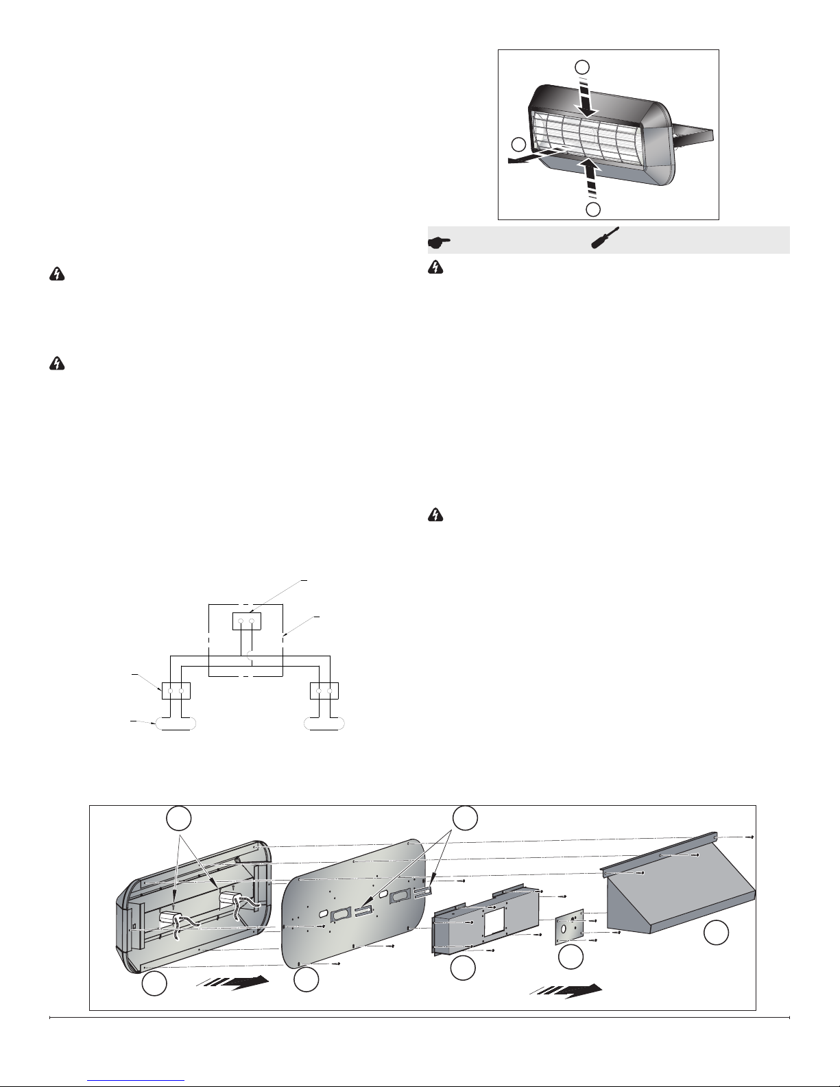
WARNING: Please ensure all packaging is removed
from the appliance before switching on. Remove the
guard as shown in Figure 3, remove element packaging
and replace guard.
SAVE THESE INSTRUCTIONS
Figure 1
General Information
Your Dimplex Ceramic Radiant Heater uses ceramic
elements which produce a high proportion of their output in
the long-wave infra-red. This provides a high comfort factor
- similar to the natural energy from the sun.
Electrical
WARNING: The installation of this appliance should
be carried out by a competent electrican and be in
accordance with National Electrical Codes (NEC)
and local codes.
The CXD2000H-NA is designed for use on a 240V AC
single phase supply.
An all-pole isolating switch with a minimum separation of
0.01ft in each pole must tted to facilitate isolation. This
switch must either be positioned inside a building or have
an IP rating against water ingress suitable for external
installation.
The appliance must be supplied through a residual current
device (RCD) having a rated residual operating current not
exceeding 30mA.
The appliance must be connected to a socket-outlet having
an grounding contact.
For supply connections use No.14 AWG or larger wire
suitable for at least 194°F(90°C).
The wiring to the appliance must be connected with a UL
approved watertight connection for outdoor use. Remove
rain shield for access to this connection and then replace
rain shield once connection is completed. Appliance must
have rain shield installed at all times during operation.
!
NOTE: Always ensure the cable grip is tightened.
Installation Instructions
Heaters are supplied with an integral wall bracket which
may be xed through the mounting holes to any suitable
structure. The bracket positions the heater at an angle of
45 degrees for optimum performance. The recommended
xing height is 72” (1.8m) from ground level. (Figure 2)
The integral wall xing bracket may be removed by fully
unscrewing to facilitate its xing.
The sitting of the heater(s) should be such as to allow an
Figure 2
7208100100R03
Page 2
CONNECT POWER
SUPPLY HERE
1000W
ELEMENT
(TYP)
WIRE DIAGRAM
TERMINAL
BLOCK (TYP)
JUNCTION BOX
1
1
2
g
c
d
b
a
(3)
(4)
(8)
f
e
(5)
even and interrupted distribution of radiation to the area(s)
to be heated.
When deciding upon the best location, condisteration must
be given to the following requirements:
Avoid structures which might vibrate, e.g. crane 1.
gantries. These could adversly affect element life.
Comfort and safety could be compromised unless the 2.
heater is mounted at or above 72” (1.8m) from ground
level.
Allow a minimum of 19 3/4” (500mm) minimum 3.
clearance between the top or side of the heater and
any horizontal surface.
WARNING: Please ensure all packaging is removed
from the appliance before switching on. Remove the
guard as shown in Figure 3, remove element packaging
and replace guard.
Wiring
WARNING:: Wiring procedures and connections should
be in accordance with the National Electric code (NEC)
and local codes.
Remove 3 screws to remove the rain shield (Figure 1.
4-A) to gain access to the control box on the back of
the heater.
Remove 4 screws to remove the terminal block plate 2.
(Figure 4-B).
Run wiring through hole in cover and connect to 3.
appropriate terminal on terminal block, and the ground
wire to screw on back of cover.
Reassemble unit.4.
Figure 3
Operation and Maintenance
WARNING: Before undertaking cleaning or
maintenance work on the appliance, disconnect the
electricty supply.
Since the appliance contains no moving parts little
maintenance is required beyond cleaning and element
replacement. It is however essential that the heater is
not operated with an accumulation of dust or dirt on the
element, as this can cause a build up of heat and eventual
damage. For this reason the heater must be inspected
regularly, depending upon conditions and at least at yearly
intervals. Allow adequate time for element and body
casing to cool before attempting to work on the heater - a
minimum of 30 minutes is recommended.
Element Replacement (Figure 4)
WARNING: Before undertaking this task ensure the
heater is disconnected from the elecetirity supply and
left to cool for a minimum of 30 minutes.
The heater should be taken off the wall.1.
Remove 3 screws to remove the rain shield (Figure 2.
4-A) to gain access to the control box on the back of
the heater.
Remove 4 screws to remove the terminal block plate 3.
(Figure 4-B) and disconnect the terminal block.
Remove 8 screws to remove the control box (Figure 4.
4-C).
This will allow access to the elements. Remove 5.
the retaining clips and spring clips (F) to loosen the
elements.
Disconnect the elements from their terminal blocks.6.
Figure 4
2
Page 3

Remove the remaining 5 screws which hold the back 7.
panel (Figure 4-D).
Remove the splash brackets (Figure 4-G) on the 8.
elements.
Bend the bars on the guard as indicated in Figure 3 to 9.
remove it.
The old element should drop out through the front of 10.
the heater, reverse the process when replacing with the
new element.
Element Replacement Kit No. - FTELLN-1-KIT (Optional).
Warranty
Products to which this limited warranty applies
This limited warranty applies to your newly purchased Dimplex outdoor
heater. This limited warranty applies only to purchases made in any
province of Canada except for Yukon Territory, Nunavut, or Northwest Territories or in any of the 50 States of the USA (and the District of Columbia)
except for Hawaii and Alaska. This limited warranty applies to the original
purchaser of the Product only and is not transferable.
Products excluded from this limited warranty
Products purchased in Yukon Territory, Nunavut, Northwest Territories,
Hawaii, or Alaska are not covered by this limited warranty. Products
purchased in these States, provinces, or territories are sold AS IS without
warranty or condition of any kind (including, without limitation, any implied
warranties or conditions of merchantability or tness for a particular
purpose) and the entire risk of as to the quality and performance of the
products is with the purchaser, and in the event of a defect the purchaser
assumes the entire cost of all necessary servicing or repair.
What this limited warranty covers and for how long
Products covered by this limited warranty have been tested and inspected
prior to shipment and, subject to the provisions of this warranty, Dimplex
warrants such products to be free from defects in material and workmanship in respect of the heater components of the Product for a period of 12
months; and in respect of the heating elements of the product for a period
of 60 days from the date of the rst purchase of the Product.
This limited warranty period also applies to any implied warranties that
may exist under applicable law. Some jurisdictions do not allow limitations
on how long an implied warranty lasts, so the above limitation may not
apply to the purchaser.
What this limited warranty does not cover
This limited warranty does not apply to Products that have been repaired
(except by Dimplex or its authorized service representatives) or otherwise
altered. This limited warranty does further not apply to defects resulting
from misuse, abuse, accident, neglect, incorrect installation, improper
maintenance or handling, operation with an incorrect power source, re or
other circumstance outside of Dimplex’s control including, without limitation, an Act of God.
What you must do to get service under this limited warranty
Defects must be brought to the attention of Dimplex Technical Service
by contacting Dimplex at 1-888-DIMPLEX (1-888-346-7539), or 1367
Industrial Road, Cambridge Ontario, Canada N1R 7G8. Please have proof
of purchase, catalogue/model and serial numbers available when calling.
Limited warranty service requires a proof of purchase of the Product.
What Dimplex will do in the event of a defect
In the event the Product or part covered by this limited warranty is proven
to be defective in material or workmanship during, in the One Year Warranty or 60 Day Warranty period, as applicable, you have the following
rights:
Dimplex will in its sole discretion either repair or replace such defec-•
tive Product or part without charge. If Dimplex is unable to repair or
replace the Product or part, or if repair or replacement is not commercially practicable or cannot be timely made, Dimplex may, in lieu
of repair or replacement, choose to refund the purchase price for the
Product or part.
Limited warranty service will be performed solely by dealers or •
service agents of Dimplex authorized to provide limited warranty
services.
The purchaser is responsible for removal and transportation of the •
Product or part (and any repaired or replacement Product or part) to
and from the authorized dealer’s or service agent’s place of business.
This limited warranty does not entitle the purchaser to on-site or in-•
home services. On-site or in-home services may be performed at the
purchaser’s specic request and expense at Dimplex’s then-current
rates for such services.
Dimplex will not be responsible for, and the limited warranty services •
shall not include, any expense incurred for installation or removal
of the Product or part (or any replacement Product or part) or any
labour or transportation costs. Such costs shall be the purchaser’s
responsibility.
What Dimplex and its dealers and service agents are also not responsible
for:
IN NO EVENT WILL DIMPLEX, OR ITS DIRECTORS, OFFICERS, OR
AGENTS, BE LIABLE TO THE PURCHASER OR ANY THIRD PARTY,
WHETHER IN CONTRACT, IN TORT, OR ON ANY OTHER BASIS, FOR
ANY INDIRECT, SPECIAL, PUNITIVE, EXEMPLARY, CONSEQUENTIAL,
OR INCIDENTAL LOSS, COST, OR DAMAGE ARISING OUT OF OR IN
CONNECTION WITH THE SALE, MAINTENANCE, USE, OR INABILITY
TO USE THE PRODUCT, EVEN IF DIMPLEX OR ITS DIRECTORS,
OFFICERS, OR AGENTS HAVE BEEN ADVISED OF THE POSSIBILITY
OF SUCH LOSSES, COSTS OR DAMAGES, OR IF SUCH LOSSES,
COSTS, OR DAMAGES ARE FORESEEABLE. IN NO EVENT WILL
DIMPLEX, OR ITS OFFICERS, DIRECTORS, OR AGENTS BE LIABLE
FOR ANY DIRECT LOSSES, COSTS, OR DAMAGES THAT EXCEED
THE PURCHASE PRICE OF THE PRODUCT. SOME JURISDICTIONS
DO NOT ALLOW THE EXCLUSION OR LIMITATION OF INCIDENTAL
OR CONSEQUENTIAL DAMAGES, SO THE ABOVE LIMITATION OR
EXCLUSION MAY NOT APPLY TO THE PURCHASER.
How State and Provincial law apply
This limited warranty gives you specic legal rights, and you may also
have other rights which vary from jurisdiction to jurisdiction. The provisions
of the United Nations Convention on Contracts for the Sale of Goods shall
not apply to this limited warranty or the sale of Product covered by this
limited warranty.
1367 Industrial Road Cambridge ON Canada N1R 7G8
1-888-346-7539 www.dimplex.com
In keeping with our policy of continuous product improvement, we reserve the right to make changes without notice.
© 2012 Dimplex North America Limited
 Loading...