

Page 1

CABM1
DE
NL
The product complies with the European Safety Standards EN60335-2-30 and the European Standard Electromagnetic Compatibility
(EMC) EN55014, EN60555-2 and EN60555-3 which cover the essential requirements of EEC Directives 73/23 and 89/336
IT
FRUK
PL
08/19152/0 - Issue 5
Page 2
1
3
5
4
BUS
IN
6
BUS
OUT
7 8
Page 3
9
10
Page 4

UK ...................................................... 6
DE ...................................................... 7
FR ...................................................... 8
NL ...................................................... 9
IT ...................................................... 10
PL ...................................................... 11
Page 5

Installation and Operating Instructions
Dimplex Air Barrier - Modular Linking Kit
Model : CABM1 (suitable for use with all CAB & DAB Models)
IMPORTANT: THESE INSTRUCTIONS SHOULD BE READ CAREFULLY AND RETAINED FOR FUTURE REFERENCE
- 5 -
UK
IMPORTANT SAFETY ADVICE
DO NOT COVER OR OBSTRUCT the air
inlet or outlet grille.
ENSURE THE APPLIANCE IS EARTHED.
Do not mount the appliance in areas where
excessive dust exists.
Always disconnect supply before working
on the product.
This product should be mounted safely to
solid wall or ceiling surfaces only.
Ensure the supply cables are of adequate
current carrying capacity and are protected
by a suitable fuse.
Ensure proper manual handling procedures
are observed at all times.
WARNING: Isolate electrical supply to ALL
modular linked units when carrying out
maintenance.
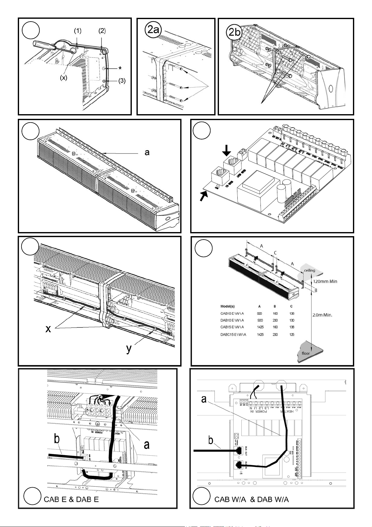
els, CABC6 for water/ambient models), through the panel knock-out
to the “BUS IN” socket on the master PCB. Fig. 4.
6. Plug one end of the Modular joining cable into the BUS OUT socket
on the Master Control board - see Fig. 4.
7. Run the modular joining cable from the Master Control board through
the knock-out hole to the adjoining Slave Control board - see ‘x’ in Fig.
5.
Clip the cable using the supplied cable clips as shown - see ‘y’ in Fig.
5.
8. Plug in connecting block at the other end of the joining cable to the
Slave “BUS IN” socket - see Fig. 4.
9. Wire independent electrical supplies to each module - see Fig. 7 for all
Models, and Fig. 8 for Water/Ambient Models.
10. Replace the bottom panel and outlet grille assembly (see ‘CAB/DAB’
Installation Instructions) and install the modular assembly by fi xing to
adjacent wall brackets positioned as shown - see Fig. 6.
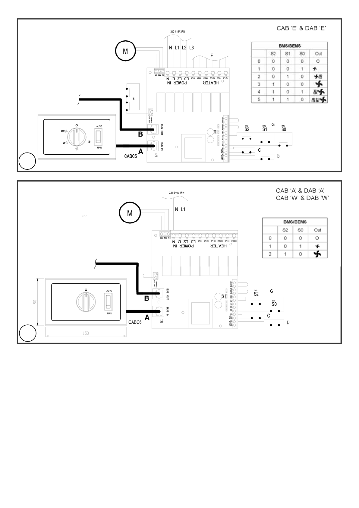
Wiring Diagram (see Fig. 9)
Electric Models - CAB ‘E’ & DAB ‘E’
A - Control Cable
B - Modular Joining Cable
C - Thermostat (Optional)
D - Door Switch (Optional)
E - Thermal Safety Cut-out Circuit
F - Elements
G - BMS Switches (Optional)
Note: If Switch Kit is used only connect to the Master Control board.
The CAB Model requires:
1 x Modular joining cable
3 x M8 x 70mm Bolts
3 x M8 nuts
3 x M8 shake-proof washers
3 x M10 x 40mm Bolts
3 x M10 nuts
3 x M10 shake-proof washers
4 x Cable clips
The Instructions for the Modular Linking Kit should be read in
conjunction with the ‘Dimplex Air Barrier’ Instructions. All ‘Safety
Advice’ to be heeded before installing the appliances.
Note: As this Kit is applicable to both CAB and DAB models there may
be fasteners etc. left over depending on which model it is used on.
The DAB Model requires:
1 x Modular joining cable
3 x M8 x 70mm Bolts
4 x M8 x 40mm Bolts
7 x M8 nuts
7 x M8 shake-proof washers
4 x Cable clips
Procedure
1. Decide which appliance is to be the master module and which of the
appliances are to be the slaves. To open the appliance remove the
outlet grille, bottom panel and the inlet grille - see ‘CAB/DAB’ Installation Instructions.
2. In order to attach the modular units together, the fi xing holes (1-3) as
indicated in Fig. 1 must be drilled using an appropriate drill size (CAB
- 10.5mm dia & DAB - 8.5mm dia). The knock-out (x) for the modular
joining cable must also be removed. While supporting the endcap,
punch a series of small holes around the perimeter of the knock-out
from inside out, using a hammer and fl at bladed screw-driver.
Note : * in Fig. 1 refers to extra hole on DAB models only.
3. Bolt modules together as shown using the supplied fi xings - see Fig.
2a & 2b.
4. Fit 25mm x 50mm unistrut (or similar - not supplied) supporting
members across the top of all bolted units which exceed 2 metres in
length (see ‘a’ in Fig. 3) before mounting into position. Otherwise link
units when fi xed in position.
5. Connect the CAT5 cable from the controller (CABC5 for electric mod-
Wiring Diagram (see Fig. 10)
Water/Ambient Models - CAB ‘A’ & DAB ‘A’
CAB ‘W’ & DAB ‘W’
A - Control Cable
B - Modular Joining Cable
D - Door Switch (Optional)
G - BMS Switches (Optional)
Note: If Switch Kit is used only connect to the Master Control board.
Recycling
For electrical products sold within the European Community.
At the end of the electrical products useful life it should not be
disposed of with household waste.
Please recycle where facilities exist. Check with your Local
Authority or retailer for recycling advice in your country.
Cleaning
WARNING: DISCONNECT SUPPLY before carrying out maintenance.
External appearance can be maintained by wiping occasionally with a
damp cloth; for stain removal, a weak soap solution can be applied with
a cloth and the surface wiped dry. Care must be taken to avoid any moisture ingress into the product.
After Sales Service
Should you require after sales service or should you need to purchase
any spares, please contact the retailer from whom the appliance was
purchased or contact the service number relevant to your country on the
warranty card.
Please do not return a faulty product to us in the fi rst instance as this may
result in loss or damage and delay in providing you with a satisfactory
service.
Please retain your receipt as proof of purchase.
Page 6

Montage- und Gebrauchsanweisung
- 6 -
Dimplex Luftschleier – Modulares Verbindungsset
Modell: CABM1 (geeignet für die Verwendung an allen CAB & DAB Modellen)
DIESE ANWEISUNG SORGFÄLTIG LESEN UND FÜR SPÄTERE REFERENZ AUFBEWAHREN.
DE
WICHTIGE SICHERHEITSHINWEISE
Lufteinlass- und Luftauslassgitter NICHT
ABDECKEN ODER BLOCKIEREN.
SICHERSTELLEN, DASS DAS GERÄT
GEERDET IST.
Dieses Gerät nicht in Bereichen betreiben,
in denen es verstärkt Staub ausgesetzt ist.
Vor dem Ausführen von Arbeiten am Gerät
stets die Spannungsversorgung trennen.
Die Geräte müssen sicher an einer stabilen
Wand- oder Deckenfl äche befestigt werden.
Sicherstellen, dass alle Leitungen über
eine entsprechende Strombelastbarkeit
verfügen und durch eine geeignete
Sicherung geschützt sind.
Sicherstellen, dass alle Anweisungen
ordnungsgemäß befolgt werden.
WARNUNG: Bei Wartungsarbeiten die
Stromversorgung
ALLER modular verbundenen Einheiten
isolieren.
CAB-Modelle benötigen:
1 x modulare Verbindungsleitung
3 x M8 x 70 mm-Schrauben
3 x M8-Muttern
3 x M8 vibrationsbeständige
Unterlegscheiben
3 x M10 x 40 mm-Schrauben
3 x M10-Muttern
3 x M10 vibrationsbeständige
Unterlegscheiben
4 x Kabelclips
Die Anweisung für das modulare Verbindungsset muss zusammen
mit der Anweisung für die „Dimplex Luftschleier“ gelesen werden. Die
Sicherheitshinweise müssen vor der Installation der Geräte befolgt
werden.
Hinweis: Da dieses Set für CAB- und DAB-Modelle verwendet
wird, können abhängig vom Modelltyp unter Umständen
Befestigungselemente etc. übrig sein.
Montageablauf
1. Festlegen, welches Gerät als Hauptmodul und welche der Geräte als
Nebenmodule fungieren sollen. Um das Gerät zu öffnen, das Auslassgitter, die untere Abdeckung und das Einlassgitter entfernen – siehe
„CAB/DAB“-Montageanweisung.
2. Um die Modelle miteinander zu verbinden, müssen die in Abb. 1
dargestellten Befestigungslöcher (1-3) mit einem entsprechend großen
Bohrer (CAB – 10,5 mm & DAB – 8,5 mm Durchmesser) gebohrt
werden. Die Ausstanzung (x) für das modulare Verbindungskabel
muss auch entfernt werden. Die Kappe festhalten und mit einem
Hammer und einem fl achen Schraubendreher eine Reihe Löcher im
Umfang der Ausstanzung von innen nach außen anbringen.
Hinweis: * in Abb. 1 bezieht sich nur auf das Extra-Loch bei DAB-
Modellen.
3. Die Module mit den beiliegenden Befestigungselementen zusammen-
schrauben – siehe Abb. 2a & 2b.
DAB-Modelle benötigen:
1 x modulare Verbindungsleitung
3 x M8 x 70 mm-Schrauben
4 x M8 x 40 mm-Schrauben
7 x M8-Muttern
7 x M8 vibrationsbeständige
Unterlegscheiben
4 x Kabelclips
4. Vor der Montage die 25 mm x 50 mm Befestigungsleisten (oder ähnliches – nicht mitgeliefert) über allen Modulen anbringen, die über zwei
Meter lang sind - siehe „a” in Abb. 3. Die anderen Einheiten verbinden,
wenn sie sich an ihrer Endposition befi nden.
5. Schließen Sie das CAT5-Kabel des Controllers (CABC5 für elektrische
Modelle, CABC6 für Wasser- / Umgebungsmodelle) durch die Öffnung
an die Buchse “BUS IN” auf der Master-Platine an. Abb. 4.
6. Stecken Sie ein Ende des modularen Verbindungskabels in die Buchse BUS OUT auf der Master-Platine - siehe Abb. 4.
7. Verbindungsleitung vom Hauptmodul durch die ausgebrochene Kabeldurchführung zur Steuerungselektronik des Nebenmoduls führen
– siehe „x“ in Abb. 5.
Verbindungsleitung mit den mitgelieferten Kabelclips befestigen –
siehe „y“ in Abb. 5.
8. 10. Den Verbindungsblock auf der anderen Seite des Verbindungskabels in die M/S INPUT-Buchse des Nebenmoduls (links) stecken
- siehe Abb. 4.
9. Unabhängige elektrische Stromversorgungen an jedes Modul anschließen - siehe Abb. 7 für elektrische Modelle und Abb. 8 für wassergeheizte/Umgebungsmodelle.
10. Die untere Abdeckplatte und die Luftauslassgitter anbringen (siehe
„CAB/DAB”-Montageanweisungen) und die modulare Baugruppe wie
abgebildet an den benachbarten Wandhalterungen montieren - siehe
Abb. 6.
Schaltplan (siehe Abb. 9)
Elektrische Modelle - CAB „E“ & DAB „E“
A - Kontrollkabel
B - Modulare Verbindungsleitung
C - Thermostat (Optional)
D - Türschalter (Optional)
E - Sicherheits-Überhitzungsschutz
F - Heizelemente
G - Gebäudemanagementsystem-Schalter (Optional)
Hinweis: Wird ein Bedienfeld verwendet, dieses nur am Hauptmodul
anschließen.
Schaltplan (siehe Abb. 10)
Wasserbeheizte/
Lüftungsmodelle - CAB „A“ & DAB „A“
CAB „W“ & DAB „W“
A - Kontrollkabel
B - Modulare Verbindungsleitung
D - Türschalter (optional)
G - Gebäudemanagementsystem-Schalter (Optional)
Hinweis: Wird ein Bedienfeld verwendet, dieses nur am Hauptmodul
anschließen.
Recycling
Für Elektrogeräte, die in der Europäischen Gemeinschaft
verkauft wurden. Kaputte Elektrogeräte dürfen nicht im
Hausmüll entsorgt werden. Wenn möglich sollten sie recycelt
werden. Informationen zu Recycling in Ihrem Land erhalten Sie
von den örtlichen Behörden oder von Ihrem Händler.
Reinigung
WARNUNG: Vor Wartungsarbeiten SPANNUNGSVERSORGUNG
TRENNEN.
Das Gehäuse kann durch gelegentliches Abwischen mit einem feuchten
Tuch gereinigt werden.Verschmutzungen mit leichter Seifenlauge entfernen und das Gehäuse anschließend abtrocknen. Darauf achten, dass
keine Feuchtigkeit in das Gehäuse eindringt.
Kundendienst
Wenn Sie den Kundendienst benötigen oder Ersatzteile bestellen möchten,
bitte den Händler kontaktieren, von dem das Gerät erworben
wurde, oder die für Ihr Land zutreffende Kundendienst- Telefonnummer auf
dem Garantieschein anrufen.
Ein fehlerhaftes Produkt bitte zunächst nicht an uns zurücksenden,
da dies Verlust oder Beschädigungen des Produkts zur Folge haben
sowie die Bereitstellung einer angemessenen Kundendienstleistung
verzögern könnte.
Bitte bewahren Sie Ihre Quittung als Kaufnachweis auf.
Page 7

Instructions d’installation et d’utilisation
Barrière d’air Dimplex – Kit de connexion modulaire
Modèle : CABM1 (compatible avec les modèles CAB et DAB)
LIRE ATTENTIVEMENT CES INSTRUCTIONS ET LES CONSERVER SOIGNEUSEMENT POUR RÉFÉRENCE ULTÉRIEURE
CONSIGNES DE SÉCURITÉ IMPORTANTES
NE PAS COUVRIR NI OBSTRUER la grille
d’entrée ou de sortie d’air.
S’ASSURER QUE L’APPAREIL EST RELIÉ À
LA MASSE.
Ne pas utiliser cet appareil dans des endroits
très poussiéreux.
Toujours débrancher l’alimentation avant
d’effectuer toute opération d’entretien sur ce
produit.
Ce produit doit être monté en toute
sécurité sur un mur ou un plafond solides
uniquement.
S’assurer que les câbles d’alimentation ont
une intensité de courant admissible correcte
et qu’ils sont protégés par un fusible adapté.
S’assurer que les instructions relatives aux
interventions manuelles sont bien respectées
à tout moment.
AVERTISSEMENT : Isoler l’alimentation
électrique de TOUTES les unités de connexion
modulaire lors de la maintenance.
Le modèle CAB requiert:
1 câble de raccordement modulaire
3 boulons M8 de 70 mm
3 écrous M8
3 rondelles indesserrables M8
3 boulons M8 de 40 mm
3 écrous M10
3 rondelles indesserrables M10
4 serre-câbles
Lire les instructions relatives au kit de connexion modulaire
en complément de celles relatives à la barrière d’air Dimplex.
Prendre soin de lire tous les conseils de sécurité avant
d’entreprendre le montage de l’appareil.
Remarque : Ce kit étant compatible à la fois avec les modèles
CAB et DAB, il peut contenir plus d’attaches et autres pièces
de fi xation que le nombre effectivement nécessaire pour le
montage de l’appareil.
Procedure
1. Déterminer le module qui sera le module principal et ceux qui seront
les modules secondaires. Pour ouvrir l’appareil, retirer la grille de
sortie d’air, le panneau inférieur et la grille d’admission d’air (voir les
instructions d’installation CAB/DAB).
2. Afi n de relier les unités modulaires, les trous de fi xation (1-3) indiqués
à la fi gure 1 doivent être percés au diamètre approprié (CAB – 10,5
mm de diamètre et DAB - 85 mm de diamètre). La partie défonçable
(x) prévue pour le passage du câble de raccordement modulaire
doit également être retirée. Tout en maintenant le support, utiliser
un marteau et un tournevis plat pour perforer une série de petits
trous autour du périmètre au niveau du côté inférieur de la partie
défonçable.
Remarque : * à la fi gure 1 fait référence à un trou supplémentaire des
modèles DAB uniquement.
3. Assembler les modules comme illustré sur les fi gures 2a et 2b à l’aide
des pièces de fi xation fournies.
4. Fixer des supports Unistrut (ou équivalents, non fournis) de 25mm x
50 mm sur le dessus des unités dont la longueur est supérieure à 2
mètres (voir élément « a » sur la fi gure 3) avant de fi xer ces dernières.
Dans le cas contraire, relier les unités une fois qu’elles sont fi xées.
Le modèle DAB requiert:
1 câble de raccordement modulaire
3 boulons M8 de 70 mm
4 boulons M8 de 40 mm
7 écrous M8
7 rondelles indesserrables M8
4 serres câbles
5. Connecter le câble CAT5 du contrôleur (CABC5 pour les modèles
électriques, CABC6 pour les modèles chauffés à l’eau ou à
température ambiante), à la prise femelle « BUS IN » sur la carte
de circuit imprimé principale en le faisant passer à travers la partie
défonçable du panneau arrière. Fig. 4.
6. Brancher une extrémité du câble de raccordement modulaire dans la
prise femelle « BUS OUT » sur la carte du module principal - voir Fig. 4.
7. Faire passer le câble de raccordement modulaire du tableau de
commandes du module principal à travers la section défonçable
jusqu’au tableau de commandes du module secondaire (voir « x » sur
la fi gure 5).
Fixer le câble à l’aide des serre-câbles comme illustré sur la fi gure 5 (« y »).
8. Brancher le bloc connecteur à l’autre extrémité du câble de
raccordement dans la prise de sortie M/S du module secondaire (côté
gauche) (voir fi gure 4).
9. Attribuer un circuit d’alimentation électrique indépendant à chaque
module (voir fi gure 7 pour les modèles électriques et fi gure 8 pour les
modèles à eau/à température ambiante).
10.Reposer le panneau inférieur et la grille de sortie (se reporter aux
instructions d’installation « CAB/DAB ») et installer le dispositif
modulaire en le fi xant à l’aide de supports muraux adjacents, comme
illustré fi gure 6.
Schéma de câblage (voir fi gure 9)
Modèles électriques – CAB « E » et DAB « E »
A - Câble de commande
B - Câble de raccordement modulaire
C - Thermostat (en option)
D - Commande de porte (en option)
E - Circuit des coupe-circuits thermiques
F - Éléments
G - Commutateurs du système de gestion énergétique du bâtiment (en option)
Remarque :En cas d’utilisation d’un panneau de commandes, ne
connecter que le tableau de commandes du module principal.
Schéma de câblage (voir fi gure 12)
Modèles chauffés à l’eau / à température ambiante CAB « A » et DAB « A »
CAB « W » et DAB « W »
A - Câble de commande
B - Câble de raccordement modulaire
D - Commande de porte (en option)
G - Commutateurs du système de gestion énergétique du bâtiment (en option)
Remarque :En cas d’utilisation d’un panneau de commandes, ne
connecter que le tableau de commandes du module principal.
Recyclage
Pour les produits électriques vendus au sein de l’Union Européenne.
Les produits électriques ne doivent pas être mis au rebut avec
les déchets ménagers lorsqu’ils arrivent en fi n de vie. Les
recycler dans les endroits prévus à cet effet. Contacter votre
administration locale ou revendeur pour connaître la procédure
de recyclage de votre pays.
Nettoyage
AVERTISSEMENT : DÉCONNECTER l’alimentation de secteur
avant d’effectuer toute opération d’entretien.
L’aspect extérieur de l’appareil peut être entretenu en essuyant ce
dernier de temps à autre avec un chiffon humide ; pour éliminer les
taches, appliquer une solution légèrement savonneuse à l’aide d’un
torchon et essuyer. Faire preuve de prudence pour empêcher toute
humidité de pénétrer dans le produit.
Service après-vente
Pour solliciter le service après vente ou se procurer des pièces détachées,
contacter le vendeur de l’appareil ou le service d’assistance du pays désiré
au numéro indiqué sur le bon de garantie.
Ne pas nous retourner un appareil défectueux sans nous avoir averti au
préalable car celui-ci risquerait de se perdre ou de subir des dommages
durant le transport ; le délai requis pour offrir un service satisfaisant à
l’utilisateur en serait inévitablement affecté.
Conserver soigneusement la facture en guise de preuve d’achat.
- 7 -
FR
Page 8
Installatie- en gebruiksinstructies
- 8 -
Dimplex luchtbuffer - modulaire verbindingsset
Uitvoering: CABM1 (geschikt voor gebruik in combinatie met alle CAB & DAB uitvoeringen)
LEES DEZE INSTRUCTIE ZORGVULDIG EN BEWAAR VOOR NASLAGDOELEINDEN
NL
BELANGRIJK VEILIGHEIDSADVIES
Het luchtinlaat- of uitlaatrooster mag NIET
WORDEN AFGEDEKT OF GEBLOKKEERD.
ZORG DAT HET APPARAAT GEAARD IS.
Gebruik dit apparaat niet op een zeer
stoffi ge locatie.
Koppel altijd de netvoeding af voordat u aan
het product gaat werken.
Dit product moet veilig worden gemonteerd,
uitsluitend aan een stevige wand of plafond.
Controleer of de voedingskabels voldoende
capaciteit hebben en door een passende
zekering zijn beveiligd.
Zorg dat de instructies voor het uitvoeren
van procedures altijd worden aangehouden.
WAARSCHUWING: Schakel bij het uitvoeren
van onderhoudswerkzaamheden de
elektriciteitstoevoer naar ALLE modulair
geschakelde eenheden uit.
De CAB-uitvoering vereist:
1 x modulaire verbindingskabel
3 x M8 x 70mm bouten
3 x M8 moeren
3 x M8 trilvaste sluitringen
3 x M10 x 40mm bouten
3 x M10 moeren
3 x M10 trilvaste sluitringen
4 x kabelklemmen
De instructies m.b.t. de modulaire verbindingsset dienen te
worden gelezen in samenhang met de instructies voor de ‘Dimplex
luchtbuffer’. Houd u aan de voorschriften in de veiligheidsinformatie
bij het installeren van de apparaten.
NB: Omdat deze set geschikt is voor zover CAB- als DABuitvoeringen
kunnen er bevestigingen e.d. over blijven, afhankelijk van het model
waarbij ze zijn gebruikt.
Werkwijze
1. Bepaal welk apparaat de hoofdmodule is en wat de nevenaparaten
worden. Om het apparaat te openen, verwijdert u het uitlaatrooster,
het onderste paneel en het inlaatrooster - zie de instructies voor de
installatie van ‘CAB/DAB’.
2. Om de modulaire eenheden aan elkaar te bevestigen moeten er
bevestigingspunten (1-3) met de juiste boorafmeting worden geboord
(CAB – 10,5 mm diam. & DAB – 8,5 mm diam.) zoals aangegeven in
Afb. 1. Het uitneembare stuk (x) voor de modulaire verbindingskabel
moet eveneens worden verwijderd.
Ondersteun de eindafsluiter en maak van binnenuit een serie kleine
gaten rond de omtrek van de uitsparing. Gebruik hiervoor een hamer
en een vlakke schroevendraaier.
NB: * in Afb. 1 verwijst naar een extra gat dat alleen aanwezig is in
DAB-uitvoeringen.
3. Bevestig de modules met bouten aan elkaar zoals aangegeven met
behulp van de bijgeleverde bevestigingen - zie Afb. 2a & 2b.
4. Bevestig vóór de montage ondersteunende 25mm x 50mm ‘unistrut’profi elen (of soortgelijk - niet bijgeleverd) aan de bovenkant van alle
eenheden met boutverbinding die langer zijn dan 2 meter (zie ‘a’ in
Afb. 3) Verbind anders de eenheden nadat ze op de juiste plaats zijn
bevestigd.
De DAB-uitvoering vereist:
1 x modulaire verbindingskabel
3 x M8 x 70mm bouten
4 x M8 x 40mm bouten
7 x M8 moeren
7 x M8 trilvaste sluitringen
4 x kabelklemmen
5. Sluit de CAT5-kabel vanaf de controller (CABC5 voor elektrische
modellen; CABC6 voor watergekoelde/ongekoelde modellen), via
de uitsparing in het paneel aan op de aansluiting BUS IN op de
hoofdprintplaat (PCB). Afb. 4.
6. Sluit het ene uiteinde van de modulaire aansluitkabel aan op de
aansluiting BUS OUT op het hoofdbedieningspaneel (MCB) - zie Afb. 4.
7. Leid de modulaire aansluitkabel vanaf de hoofdprint door het gemaakte
gat naar de aangrenzende secundaire print - zie ‘x’ in Afb. 5.
Klem de kabel vast met de bijgeleverde kabelklemmen, zoals
aangegeven - zie ‘y’ in Afb. 5.
8. Sluit het aansluitblok aan de andere kant van de verbindingskabel
aan op het secundaire aansluitpunt M/S INPUT (links) - zie Afb. 4.
9. Sluit onafhankelijke elektrische voedingen aan op alle modules
– zie Afb. 7 voor elektrische uitvoeringen en Afb. 8 voor water-/
luchtverhittingsuitvoeringen.
10. Plaats het onderste paneel en de uitlaatroosterconstructie terug
(zie ‘CAB/DAB’ installatie-instructies) en installeer de modulaire
constructie door deze te bevestigen aan aangrenzende muurbeugels
in de aangegeven posities - zie Afb. 6.
Bedradingsschema (zie Afb. 9)
Elektrische uitvoeringen - CAB ‘E’ & DAB ‘E’
A - Besturingskabel
B - Modulaire aansluitkabel
C - Thermostaat (optie)
D - Deurschakelaar (optie)
E - Onderbreekcircuit thermische beveiliging
F - Elementen
G - BMS-schakelaars (optioneel)
NB: Als de schakelaarset wordt gebruikt, deze alleen aansluiten op de
hoofdprint.
Bedradingsschema (zie Afb. 10)
Water/Ambient Models - CAB ‘A’ & DAB ‘A’
CAB ‘W’ & DAB ‘W’
A - Besturingskabel
B - Modulaire aansluitkabel
D - Deurschakelaar (optie)
G - BMS-schakelaars (optioneel)
NB: Als de schakelaarset wordt gebruikt, deze alleen aansluiten op de
hoofdprint.
Recyclen
Voor elektrische producten verkocht binnen de Europese Unie.
Na het verstrijken van de levensduur van elektrische producten
mogen zij niet worden weggeworpen met het normale huisafval.
Als er recycle-faciliteiten beschikbaar zijn, maak daar dan
gebruik van. Neem contact op met de locale overheidsinstanties
of de winkel waar u het apparaat hebt gekocht voor informatie
over recyclen.
Reiniging
WAARSCHUWING: SCHAKEL NETVOEDING UIT alvorens onderhoud
uit te voeren.
Wrijf de buitenkant van het apparaat zo nu en dan schoon met een
vochtige doek; breng voor het verwijderen van vlekken met een doek
een mild zeepsopje aan en wrijf droog. Pas op en voorkom dat vocht het
product kan binnendringen.
After Sales Service
Als u na aankoop service nodig hebt of als u reserve-onderdelen wilt
aanschaffen, neem dan contact op met de winkel waar u de kachel hebt
gekocht of bel het servicenummer voor uw land dat op het garantiebewijs
staat.
Stuur nooit meteen een kapotte kachel naar ons op omdat dit verlies of
schade zou kunnen veroorzaken en u misschien langer op bevredigende
service moet wachten.
Bewaar de bon als bewijs van aankoop.
Page 9

Istruzioni per l’installazione e il funzionamento
Barriera d’aria Dimplex – Kit di collegamento modulare
Modello: CABM1 (idoneo all’utilizzo con tutti i modelli CAB & DAB)
LEGGERE ATTENTAMENTE LE ISTRUZIONI RIPORTATE DI SEGUITO E CONSERVARLE PER OGNI RIFERIMENTO FUTURO
4.
IMPORTANTE RACCOMANDAZIONE DI
SICUREZZA
NON COPRIRE O OSTRUIRE la griglia di
presa o di mandata dell’aria.
ASSICURARSI CHE IL DISPOSITIVO SIA
COLLEGATO A TERRA.
Non montare il prodotto in ambienti molto
polverosi.
Prima di effettuare lavori di riparazione o
modifi ca del prodotto, scollegare sempre la
corrente elettrica.
Per garantire la sicurezza, il prodotto
deve essere montato solo a muri o soffi tti
massicci.
Assicurarsi che i fi li della corrente siano
in grado di condurre il carico di corrente
esatta e siano protetti da fusi appropriati.
Assicurarsi di manipolare sempre il
prodotto secondo le corrette procedure.
AVVERTENZA: isolare l’alimentazione
elettrica di TUTTE le unità modulari
collegate durante gli interventi di
manutenzione.
Installare supporti unistrut da 25 mm x 50 mm (o simili, non in dotazione)
sul lato superiore delle unità collegate, ma non ancora fi ssate in
posizione, che superano i 2 metri di lunghezza (vedi ‘a’ in Fig. 3).
Alternativamente, collegare le unità dopo averle fi ssate in posizione.
5. Collegare il cavo CAT5 dal controller (CABC5 per modelli elettrici,
CABC6 per modelli acqua/ambiente), attraverso il foro del pannello
alla presa “BUS IN” sulla scheda master . Fig. 4.
6. Inserire un’estremità del cavo di connessione modulare nella presa
BUS OUT sulla scheda master - vedi Fig. 4.
7. Far passare il cavo di collegamento modulare dal circuito di controllo
principale, attraverso il foro prestampato, fi no al circuito di controllo
secondario - vedere ‘x’ in Fig. 5.
Fermare il cavo con i serracavi forniti in dotazione come mostrato –
vedere ‘y’ in Fig. 5.
8. Inserire il blocco connettore situato all’altra estremità del cavo di
collegamento nella presa INGRESSO M/S secondaria (a sinistra) vedere Fig. 4.
9. Collegare l’alimentazione elettrica separatamente per ciascun modulo
- vedere Fig. 7 per i modelli riscaldati a elettricità e Fig. 8 per i modelli
ad acqua/temperatura ambiente.
10. Riposizionare il pannello inferiore e la griglia di mandata dell’aria
(vedi le Istruzioni per l’installazione ‘CAB/DAB’) e installare il gruppo
modulare fi ssandolo alle staffe a parete adiacenti, posizionate come
mostrato in Fig. 6.
Schema elettrico (vedere Fig. 9)
Modelli elettrici - CAB ‘E’ & DAB ‘E’
A - Cavo di controllo
B - Cavo di connessione modulare
C - Termostato (opzionale)
D - Interruttore a porta (opzionale)
E - Circuito di interruttori di sicurezza termici
F - Elementi
G - Interruttori BMS (Opzionali)
Nota: qualora si utilizzi il Kit interruttori, eseguire il collegamento solo con
il circuito di controllo principale.
- 9 -
IT
Il modello CAB richiede:
1 x cavo di collegamento modulare
3 x bulloni M8 x 70mm
3 x dadi M8
3 x rondelle dentate a ventaglio M8
3 x bulloni M10 x 40mm
3 x dadi M10
3 x rondelle dentate a ventaglio M10
4 x serracavi
Le istruzioni relative al Kit di collegamento modulare vanno lette
assieme alle istruzioni della ‘Barriera d’aria Dimplex’. È necessario
prestare attenzione alle raccomandazioni di sicurezza prima di
installare l’apparecchiatura.
Nota: visto che questo kit si riferisce sia ai modelli CAB che DAB, è
possibile che rimangano inutilizzati degli elementi di fi ssaggio o altro,
a seconda del modello considerato.
Il modello DAB richiede:
1 x cavo di collegamento modulare
3 x bulloni M8 x 70mm
4 x bulloni M8 x 40mm
7 x dadi M8
7 x rondelle dentate a ventaglio M8
4 x serracavi
Procedura
1. Stabilire quale debba essere l’apparecchiatura principale e quali le
apparecchiature secondarie. Per aprire l’apparecchiatura, rimuovere
la griglia di mandata dell’aria, il pannello inferiore e la griglia di presa
dell’aria – vedere Istruzioni per l’installazione CAB/DAB.
2. Per collegare le unità modulari, i fori di fi ssaggio (1-3) indicati in Fig. 1
devono essere ricavati con un trapano di dimensioni adeguate (CAB:
10,5 mm dia; DAB: 8,5 mm dia). È necessario inoltre rimuovere il
preforo (x) per il cavo di collegamento modulare.
Sostenendo il cappuccio terminale, ricavare una serie di forellini
attorno al perimetro del preforo dall’interno verso l’esterno con un
martello e un cacciavite a lama piatta.
Nota: * in Fig. 1 si riferisce al foro supplementare presente solo sui
modelli DAB.
3. Unire i moduli come indicato facendo uso degli elementi di fi ssaggio
forniti in dotazione - vedere Fig. 2a & 2b.
Schema elettrico (vedere Fig. 10)
Modelli ad acqua/ambientali - CAB ‘A’ & DAB ‘A’
CAB ‘W’ & DAB ‘W’
A - Cavo di controllo
B - Cavo di connessione modulare
D - Interruttore a porta (opzionale)
G - Interruttori BMS (Opzionali)
Nota: qualora si utilizzi il Kit interruttori, eseguire il collegamento solo con
il circuito di controllo principale.
Riciclaggio
Prodotti elettrici venduti nell’ambito della Comunità Europea.
Quando i prodotti elettrici non sono più utilizzabili, non possono
essere smaltiti assieme ai normali rifi uti domestici, bensì in
apposite discariche. Per informazioni sui servizi di riciclaggio
locali, rivolgersi all’amministrazione locale o al proprio
rivenditore di fi ducia.
Pulitura
AVVERTENZA: SCOLLEGARE LA CORRENTE ELETTRICA prima
di eseguire opere di manutenzione.
Per tenere pulite le unità, è suffi ciente passarvi sopra di tanto in tanto
un panno inumidito; per rimuovere possibili macchie, strofi nare la
superfi cie con un panno bagnato in una soluzione di acqua e poco
sapone, quindi asciugare. È necessario evitare di far colare liquidi di
qualunque genere all’interno del prodotto.
Servizio di assistenza clienti
Per l’assistenza post-vendita o per l’acquisto di parti, rivolgersi al proprio
rivenditore o al numero dell’assistenza del proprio paese indicato sulla
garanzia.
Non restituire un prodotto difettoso senza aver prima contattato l’assistenza,
onde evitare la perdita o il danneggiamento dello stesso e la conseguente
impossibilità di fornire al cliente un servizio soddisfacente.
Conservare la ricevuta come prova d’acquisto.
Page 10

Instrukcja instalacji i obsługi
Kurtyna powietrzna fi rmy Dimplex – zestaw do łączenia modułowego
Model: CABM1 (do użytku z wszystkimi modelami serii CAB i DAB)
NINIEJSZĄ INSTRUKCJĘ NALEŻY DOKŁADNIE PRZECZYTAĆ I ZACHOWAĆ DO WYKORZYSTANIA W PRZYSZŁOŚCI.
WAŻNE ZALECENIA DOTYCZĄCE
BEZPIECZEŃSTWA
NIE ZAKRYWAJ CAŁKOWICIE ANI
CZĘŚCIOWO wlotu powietrza lub kratki
wylotowej.
UPEWNIJ SIĘ, CZY URZĄDZENIE ZOSTAŁO
UZIEMIONE.
Nie instaluj urządzenia w miejscu o
nadmiernym zapyleniu.
Zawsze odłączaj zasilanie przed
przystąpieniem do demontażu urządzenia.
Produkt ten musi być bezpiecznie
zamocowany, wyłącznie do mocnej ściany
lub sufi tu.
Upewnij się, że kable zasilające mają
wymaganą obciążalność prądową i są
zabezpieczone właściwym bezpiecznikiem.
Zawsze przestrzegaj obowiązujących zasad
obchodzenia się z urządzeniem.
OSTRZEŻENIE: Przed przystąpieniem
do konserwacji, należy odłączyć źródło
zasilania od WSZYSTKICH połączonych
modułowo urządzeń.
Wymagane elementy dla
modelu CAB:
1 modularny kabel łączący
3 śruby M8 x 70 mm
3 nakrętki M8
3 podkładki antywibracyjne M8
3 śruby M10 x 40 mm
3 nakrętki M10
3 podkładki antywibracyjne M10
4 zaciski kablowe
Niniejsza instrukcja instalacji wymaga równoczesnego zapoznania
się z instrukcją obsługi kurtyny powietrznej fi rmy Dimplex. Przed
przystąpieniem do instalacji urządzenia należy uwzględnić wszystkie
zalecenia dotyczące bezpieczeństwa.
Uwaga: Ponieważ niniejszy zestaw ma zastosowanie zarówno do
modeli CAB, jak i DAB, zależnie od modelu po instalacji mogą
pozostać niewykorzystane elementy mocujące itp.
Procedura
1. Zadecyduj, które urządzenie ma być modułem głównym, a które z
urządzeń mają być modułami podrzędnymi. Aby otworzyć urządzenie,
zdemontuj kratkę wylotową, dolną pokrywę oraz kratkę wlotową –
patrz „Instrukcja instalacji urządzenia CAB/DAB”.
2. Aby połączyć ze sobą urządzenia modułowe, należy wywiercić otwory
(1-3) widoczne na rys. 1, używając wiertła o odpowiedniej średnicy
(CAB - średnica 10,5 mm, a DAB - średnica 8,5 mm). Zaślepka (x)
kabla łączenia modułowego musi być wyjęta. Podtrzymując obudowę,
wybić od wewnątrz, za pomocą młotka i płaskiego śrubokrętu, kilka
małych otworów na obwodzie zaślepki.
Uwaga: Symbol * na rys. 1 oznacza dodatkowy otwór, tylko w
modelach DAB.
3. Skręć ze sobą moduły, używając dostarczonych elementów
mocujących, zgodnie z rys. 2a i 2b.
4. Przed zamocowaniem w docelowym miejscu urządzeń przykręcanych,
których długość przekracza 2 metry, należy zamontować w ich górnej
Wymagane elementy dla modelu
DAB:
1 modularny kabel łączący
3 śruby M8 x 70 mm
4 śruby M8 x 40 mm
7 nakrętek M8
7 podkładek antywibracyjnych M8
4 zaciski kablowe
części, w kierunku poprzecznym, rozpórkę 25 mm x 50 mm (lub
podobny element — nie należy do wyposażenia) — patrz „a” na rys. 3.
W przeciwnym razie połączyć urządzenia po zamocowaniu na
miejscu.
5. Podłącz kabel CAT5 z kontrolera (CABC5 dla modeli elektrycznych,
CABC6 dla modeli wodnych/otoczenia), przez wybijany element panelu do gniazda „BUS IN” na głównej płytce drukowanej PCB. Rys. 4.
6. Podłącz jeden koniec kabla łączenia modułowego do gniazda BUS
OUT na głównej płytce sterowania - patrz rys. 4.
7. Przez zrobiony otwór przeprowadź modularny kabel łączący od karty
sterującej moduł
podrzędnego – „x” na rys. 5.
Zepnij kabel, używając dostarczonych zacisków kablowych – „y” na
rys. 8.
8. Włożyć wtyczkę łączącą na drugim końcu kabla łączącego do gniazda
M/S INPUT (wejście nadrzędny/podrzędny) w module podrzędnym (z
lewej strony) – patrz rys. 4.
9. Przewód pozwala na niezależne zasilenie wszystkich modułów —
modele sterowane elektrycznie: patrz rys. 7; modele z obiegiem wody/
powietrza: rys. 8.
10. Z powrotem założyć panel dolny i zespół kraty wylotowej (patrz
instrukcje montażu CAB/DAB) i zamontować zespół modułowy,
łącząc go ze wspornikami ściennymi rozmieszczonymi w sposób
przedstawiony na rys. 6.
u głównego do sąsiedniej karty sterującej modułu
Schemat połączeń (patrz rys. 9)
Schematy elektryczne – CAB „E” i DAB „E”
A - Kabel sterowania
B - Kabel łączenia modułowego
C - Termostat (opcjonalny)
D - Przełącznik w drzwiach (opcjonalny)
E - Obwód zabezpieczenia termicznego
F - Elementy
G - Przełączniki BMS (opcjonalnie)
Uwaga: Jeżeli używany jest zestaw przełączników, podłącz go tylko
do karty sterującej modułu głównego.
Schemat połączeń (patrz rys. 10)
Schematy obiegu wody/powietrza – CAB „A” i DAB „A”
A - Kabel sterowania
B - Kabel łączenia modułowego
D – Przełącznik drzwiowy (opcjonalnie)
G – Przełączniki BMS (opcjonalnie)
Uwaga: Jeżeli używany jest zestaw przełączników, podłącz go tylko
do tablicy sterowania modułu głównego.
Recykling
Dla urządzeń elektrycznych sprzedawanych na
terenie Unii Europejskiej.
Urządzenia nie wolno utylizować wraz z odpadami domowymi.
Należy je oddać do utylizacji. W celu uzyskania szczegółowych
informacji odnośnie utylizacji proszę skontaktować się z
lokalnymi władzami.
Czyszczenie
OSTRZEŻENIE: Przed rozpoczęciem konserwacji należy
ODŁĄCZYĆ ZASILANIE.
Powierzchnie zewnętrzne można konserwować, sporadyczne
przecierając je wilgotną szmatką. Do usuwania plam należy użyć
szmatki zamoczonej w słabym roztworze mydła, a następnie wytrzeć
powierzchnię do sucha. Należy uważać, aby do urządzenia nie
dostawała się wilgoć.
Serwis posprzedażny
Gdy zajdzie potrzeba skorzystania z obsługi posprzedażowej lub
zakupu części zamiennych, należy skontaktować się ze sprzedawcą
urządzenia lub zadzwonić na podany na karcie gwarancyjnej numer
serwisu w danym kraju.
Nie należy od razu odsyłać uszkodzonego urządzenia do producenta,
ponieważ może to spowodować jego utratę, uszkodzenie lub
opóźnienie naprawy.
Paragon lub fakturę należy zachować jako dowód zakupu.
- 10 -
PL
CAB „W” i DAB „W”
Page 11

DE - Garantie
Die nachstehenden Ausführungen über Umfang der Garantie,
Garantiefristen und die Anmeldung von Garantieansprüchen gelten
ausschließlich für die
Bundesrepublik eutschland. Wir räumen dem Käufer nach seiner Wahl
zusätzlich zu den ihm gegen den Verkäufer ausstehenden gesetzlichen
Gewährleistungsansprüchen einen Anspruch nach Maßgabe der
nachfolgenden Garantieverpfl ichtung ein:
I. Dauer und Beginn der Garantie
1. Grundsätzlich wird für jedes im Haushalt eingesetzte Gerät die auf der
Garantiekarte ausgezeichnete Garantiezeit gewährt.
2. Bei gewerblicher Nutzung der von der Bauart her für den Haushalt
bestimmten Geräte beträgt die Garantiezeit lediglich sechs Monate.
3 Die Garantie ist mit dem Zeitpunkt der Übergabe des Gerätes wirksam.
4. Bewahren Sie die vom Verkäufer ausgefüllte Garantie-Urkunde mit der
Rechnung, dem Lieferschein oder einem anderen Kaufnachweis auf.
5. Durch Garantieleistungen tritt keine Verlängerung der ursprünglichen
Garantiezeit ein.
6. Garantieansprüche können nur geltend gemacht werden, wenn die
Mängelrüge innerhalb von 14 Tagen nach Entdeckung des Mangels
schriftlich bei uns eingeht.
II. Inhalt und Unfang der Garantie
1. Ihr Gerät wird sorgfältig geprüft. Für den Fall, daß der Garantieanspruch
zu Recht besteht, entscheiden wir, auf welche Art der Schaden behoben wer
den soll / wird. Im Reparaturfall sorgen wir für eine fachgerechte Ausführung.
2. Bei der Einsendung zur Reparatur sind Garantie-Urkunde und
Kaufnachweis beizufügen.
3. Innerhalb der ersten sechs Monate erbringen wir die Garantieleistungen
ohne Berechnung von Nebenkosten (Fahrt- und Wegzeitkosten, Fracht- und
Verpackungskosten).
4. Darüber hinausgehende Ansprüche, insbesondere
Schadenersatzansprüche, sind ausgeschlossen, soweit eine Haftung nicht
gesetzlich angeordnet ist.
III. Einschränkungen der Garantie
1. Eine Garantie besteht nicht bei Fehlern oder Mängeln, die auf folgendes
zurückzuführen sind:
a) Reparaturen und Abänderungen, die von nicht autorisierter dritter Stelle
vorgenommen werden oder wurden;
b) äußere Einwirkungen, zum Beispiel Transportschäden, Beschädigungen
durch Stoß oder Schlag, Schäden durch Witterungseinfl üsse oder sonstige
Naturerscheinungen;
c) unsachgemäße / fehlerhafte Bedienung oder Beanspruchung;
d) Verwendung von ungeeigneten Reinigungsmitteln, Chemikalien usw.
2. Die Garantie erstreckt sich nicht auf leicht zerbrechliche Teile, zum
Beispiel Glas, Kunststoff, Glühlampen.
3. Geringfügige Änderungen gegenüber Prospekten oder Mustern oder
früher gelieferter Ware gelten nicht als Mangel. Gleiches gilt bei lediglich
geringfügigen Abweichungen von der Sollbeschaffenheit, die für Wert- und
Gebrauchstauglichkeit des Gerätes unerheblich ist.
4. Im Ausland gelten die von unserer jeweils zuständigen Landesvertretung
herausgegebenen Garantiebedingungen.
DE - Garantie Für
dieses Gerät gelten
die in dem Kaufl and
herausgegebenen
Garantie-bedingungen.
Einzelheiten teilt Ihnen
der Händler, bei dem
Sie das Gerät gekauft
haben, auf Anfrage
jederzeit mit. Die
Inanspruchnahme von
Garantieleistungen
setzt die Vorlage des
Kaufbeleges und
die Einhaltung der
Garantiefrist voraus.
Der Garantieanspruch
verfällt, wenn das
Gerät beschädigt, nicht
sachgemäß benutzt
oder unbefugte Eingriffe
vorgenommen wurden.
UK - Warranty The
warranty conditions in
the country of purchase
apply to this appliance.
Information can be
obtained at any time
from the retailer from
whom the appliance
was purchased. For
claims under guarantee
the sales receipt
must be produced
and the claims must
be forwarded within
the guarantee period.
The right to claim
under guarantee
expires in case that
the device has been
damaged, used in
an inappropriate way
or that unauthorized
manipulations have
been carried out.
FR- Garantie Pour cet
appareil, les garanties
applicables sont celles
en vigueur dans le
pays où a lieu l’achat.
Votre revendeur vous
en communiquera à
tout moment les détails
sur simple demande.
La revendication au
droit à la garantie
est assujettie à la
présentation de la
preuve d’achat et
du respect du délai
de garantie. Le droit
à la garantie expire
lorsque l’appareil a été
endommagé, utilisé de
manière inadéquate ou
que des interventions
ont été effectuées par
des tiers.
IT - Garanzia Per
questo apparecchio
valgono le condizioni
di garanzia pubblicate
nel Paese d’acquisto.
I dettagli a riguardo
vengono forniti, in ogni
momento, su richiesta,
dal rivenditore presso il
quale viene acquistato
l’apparecchio. Il diritto
alla prestazione di
garanzia ha come
premessa l’esibizione
dello scontrino di
acquisto e l’osservanza
del termine di garanzia.
Il diritto alla copertura di
garanzia non sussiste,
se l’apparecchio è
stato danneggiato, se
non è stato utilizzato
a regola d’arte e sono
stati effettuati su di
esso interventi non
autorizzati.
NL- Garantie Voor dit
apparaat gelden de in
het kooplanf uitgegeven
garantievoorwaarden.
Details deelt U Uw
dealer, waar U het
apparaat heeft gekocht,
op aanvrag altijd mee.
De gebruikmaking van
garantievergoedingen
vereist het overleggen
van het koopbewijs
en de nakoming van
de garantietermijn. De
garantieclaim vervalt,
wanneer het apparaat
werd beschadigd, niet
juist werd gebruikt of
onbevoegde ingrepen
werden uitgevoerd.
PL- Gwarancja Dla
tego urządzenia
obowiązują warunki
gwarancji wydane w
kraju zakupu. W każdej
chwili sprzedawca,
u którego dokonano
zakupu urządzenia,
przekaże Państwu
odpowiednie szczegóły.
Wykorzystanie
świadczeń
gwarancyjnych jest
uwarunkowane
przedłożeniem
pokwitowania zakupu i
zachowaniem terminu
gwarancji. Prawo do
gwarancji przepada,
gdy urządzenie
zostanie uszkodzone,
niepoprawnie używane
lub dokonane zostaną
niedozwolone
manipulacje.
Page 12

1. Garantiekarte 2. Garantiezeitraum 3. Modell(e) 4. Modellbezeichnung
3 CABM1
5. Kaufdatum 6. Stempel & Unterschrift des Einzelhändlers
7. Fehler/Defekt
8. Kontakt-Tel.-Nr.
& - Anschrift
DE
Glen Dimplex Deutschland GmbH
Goldenen Feld 18
D-95326 Kulmbach
11/05/A
Tel. 09221 709-564
Fax. 09221 709 565
kundendienst.hauswaerme@glendimplex.de
UK
Glen Dimplex UK Limited
Millbrook House
Grange Drive
Hedge End
Southampton
Hampshire. SO30 2DF
Tel. 0870 7270101
Fax. 0870 7270102
customer.services@glendimplex.com
IE
Dimpco Ltd.
Airport Road
Cloghran
Co. Dublin
Republic of Ireland
Tel: 01 8424833
Fax. 01 8424839
PL
Glen Dimplex Polska Sp. z o.o.
ul. Strzeszyñska 33
60-479 Poznañ
Poland
Tel. 061 8425 805
Fax. 061 8425 806
offi ce@glendimplex.pl
UK
1. Warranty Card
2. Guarantee Period (in Years)
3. Model(s)
4. Model Name
5. Date of Purchase
6. Stamp & Signature of retailer
7. Fault/Defect
8. Contact Number & Address
DE
1. Garantiekarte
2. Garantiezeitraum (in Jahre)
3. Modell(e)
4. Modellbezeichnung
5. Kaufdatum
6. Stempel & Unterschrift
des Einzelhändlers
7. Fehler/Defekt
8. Kontakt-Tel.-Nr. & - Anschrift
FR
1. Bon de garantie
2. Période de garantie (en
années)
3. Modèle(s)
4. Intitulé du modèle
5. Date d’achat
6. Cachet et signature du
vendeur
7. Anomalie/Défaut
8. Nom et adresse du contact
IT
1. Scheda di garanzia
2. Periodo di garanzia (in anni)
3. Modello(i)
4. Nome del modello
5. Data di acquisto
6. Timbro e fi rma del rivenditore
7. Guasto/difetto
8. Indirizzo e numero di contatto
NL
1. Garantiebewijs
2. Garantieperiode (in jaren)
3. Model(len)
4. Modelnaam
5. Aankoopdatum
6. Stempel & Ondertekening
detaillist
7. Fout/Defect
8. Telefoonnummer & Adres
PL
1. Karta gwarancyjna
2. Okres gwarancji (w latach)
3. Model(e)
4. Nazwa modelu
5. Data zakupu
6. Pieczec i podpis sprzedawcy
7. Usterka
8. Telefon i adres kontaktowy
 Loading...