

Page 1
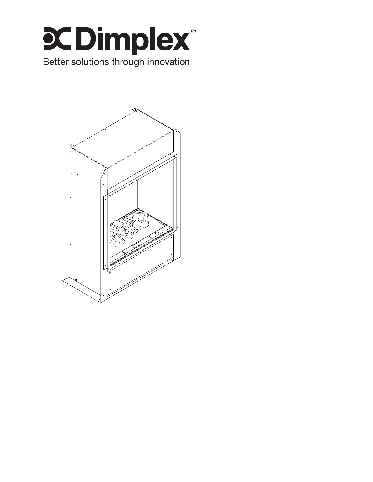
Owner’s Manual
Model
BOF4056
BOF4068
BOF6056
7213470100R01
IMPORTANT SAFETY INFORMATION: Always read this manual
rst before attempting to install or use the wall mount engine. For
your safety, always comply with all warnings and safety instructions
contained in this manual to prevent personal injury or property
damage.
To view the full line of Dimplex products, please visit
www.dimplex.com
Page 2
2 www.dimplex.com
Table of Contents
Always use a qualied technician
or service agency to repair
this engine.
!
NOTE: Procedures and
techniques that are considered
important enough to
emphasize.
CAUTION: Procedures and
techniques which, if not
carefully followed, will result in
damage to the equipment.
WARNING: Procedures
and techniques which, if not
carefully followed, will expose
the user to the risk of re,
serious injury, or death.
Welcome & Congratulations ....................3
IMPORTANT INSTRUCTIONS ..................4
Installation ..................................6
Assembly ..................................10
Operation ..................................12
Maintenance ...............................15
Warranty .................................17
Replacement Parts ..........................19
Page 3
3
Welcome & Congratulations
Thank you and congratulations for choosing to purchase an Optimyst®
Pro engine from Dimplex, the world leader in electric replaces.
Please carefully read and save these instructions.
CAUTION: Read all instructions and warnings carefully before
starting installation. Failure to follow these instructions may result in a
possible electric shock, re hazard and will void the warranty.
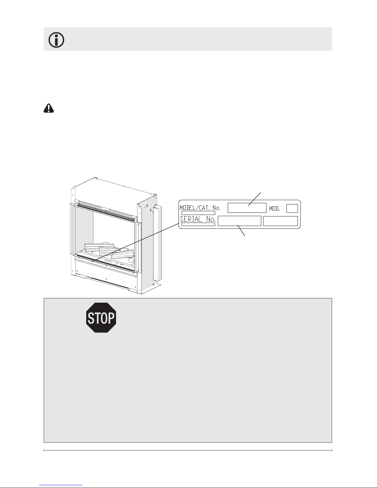
Please record your model and serial numbers below for future
reference: model and serial numbers can be found on the Model and
Serial Number Label of your wall mount engine.
NO NEED TO RETURN TO THE STORE
Questions with operation or assembly? Require Parts Information?
Product Under Manufacturer’s Warranty?
Contact us at: www.dimplex.com/customer_support
For Troubleshooting and Technical Support
OR Toll-Free 1-888-DIMPLEX (1-888-346-7539)
Monday to Friday 8:00 a.m. to 4:30 p.m. EST
Please have your model number and product serial
number ready. (See above)
Model Number
Serial Number
Page 4

4 www.dimplex.com
When using electrical appliances,
basic precautions should always
be followed to reduce the risk of
fire, electric shock, and injury to
persons, including the following:
① Read all instructions before
using the engine.
②
The heater is hot when in use.
To avoid burns, do not let bare skin
touch hot surfaces. The trim around
the heater outlet becomes hot during heater operation.
DANGER:
High temperatures
may be generated under certain abnormal conditions. Do not partially
of fully cover the front of this heater.
③
Extreme caution is necessary
when any heater is used by or near
children or invalids and whenever
the unit is left operating and unattended.
④ Always unplug the engine
when not in use.
⑤ Do not operate any unit with
a damaged cord or plug, or if
the engine has been dropped or
damaged in any manner. Contact
Dimplex Technical Service at
1-888-346-7539.
⑥ Do not use outdoors.
IMPORTANT INSTRUCTIONS
⑦ Never locate unit where it may
fall into a bathtub or other water
container.
⑧ To disconnect the unit, turn
the controls off, then remove the
plug from the outlet or disconnect
power at the service panel.
⑨ Always use properly grounded,
fused and polarized outlets.
⑩
Do not insert or allow foreign
objects to enter any ventilation or
exhaust opening as this may cause
an electric shock or re, or damage
to the heater.
⑪
To prevent a possible re, do not
block air intake or exhaust in any
manner. Do not use on soft surfaces, like a bed, where openings may
become blocked.
⑫
All electrical heaters have hot
and arching or sparking parts inside.
Do not use in areas where gasoline,
paint, or ammable liquids are used
or stored or where the unit will be
exposed to ammable vapors.
⑬ Do not modify the engine.
Use it only as described in this
manual. Any other use not recommended by the manufacturer may
cause re, electric shock or injury
to persons.
Page 5
5
SAVE THESE INSTRUCTIONS
⑭
To reduce the risk of electric
shock, this appliance must be
grounded. Avoid the use of an extension cord. Extension cords may
overheat and cause a risk of re.
Always plug heaters directly into a
wall outlet/receptacle. Never use
with an extension cord or relocatable power tap (outlet/power strip).
⑮ Do not burn wood or other
materials in the engine.
⑯ Always use a certied electrician should new circuits or outlets
be required.
⑰ Disconnect the power supply
before performing any cleaning,
maintenance or relocation of the
unit.
⑱ When transporting or storing the unit and cord, keep in a
dry place, free from excessive
vibration and store so as to avoid
damage.
⑲
The wall mount engine must
not be located directly below a
socket outlet.
⑳ The wall mount engine must
be positioned so that the plug is
accessible.
WARNING: Remote control
contains small batteries. Keep
away from children. If swallowed,
seek medical attention immediately.
WARNING: Do not install battery backwards, charge, put in re
or mix with used or other battery
types - may explode or leak causing injury.
!
NOTE: Changes or modica-
tions not expressly approved by
the party responsible for compliance could void user's authority to
operate the equipment.
IMPORTANT INSTRUCTIONS
CAUTION
RISK OF ELECTRIC SHOCK
DO NOT OPEN
NO USER-SERVICEABLE PARTS INSIDE
Page 6
6 www.dimplex.com
Installation
The Optimyst Pro is supplied
in an assembled state and is
designed to be permanently installed. The unit comes ready for
hardwire installation.
WARNING: Construction and
electrical outlet wiring must
comply with local building
codes and other applicable
regulations to reduce the risk
of re, electric shock and injury
to persons.
WARNING: To reduce the
risk of re, do not store or use
gasoline or other ammable
vapors or liquids in the vicinity
of the heater.
!
NOTE: A 15 Amp, 120 Volt cir-
cuit is required. A dedicated circuit
is preferred but not essential in all
cases. A dedicated circuit will be
required if, after installation, the
circuit breaker trips or the fuse
blows on a regular basis when the
heater is operating. Additional appliances on the same circuit may
exceed the current rating of the
circuit breaker.
WARNING: Failure to install
the replace as instructed
below may result in damage
to the equipment and or may
expose the user to the risk of
re, serious injury, illness or
death.
WARNING: Do not attempt to
wire your own new outlets or
circuits. To reduce the risk of
re, electric shock or injury to
persons, always use a licensed electrician.
WARNING: Ensure that the
On/Off switch is set to the Off
position (refer to Operation
section) and that the circuit
on which the replace is to be
installed has the power cut off
at the service panel until installation is complete.
!
NOTE: Please read all instruc-
tions before installing.
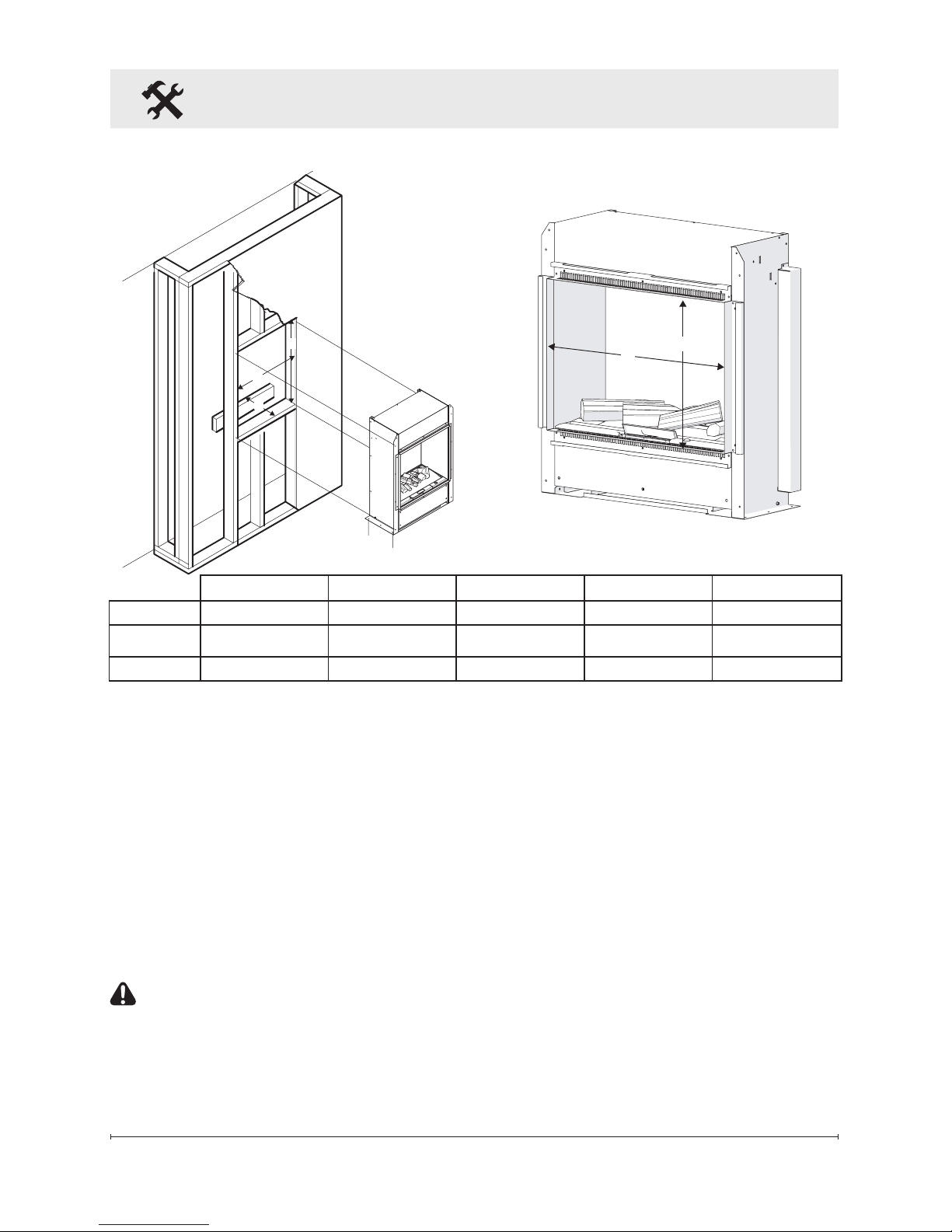
1. For rough in framing, the
opening should follow the
recommended dimensions
located in Figure 1.
!
NOTE: Dimensions provided
are minimum clearances and will
vary depending on type of support
framing and nishing options.
!
NOTE: It is recommended
that the bottom of the unit not be
mounted higher than 40 in. (1020
mm) from the ground to maintain
an optimized viewing angle of the
ame (Figure 2).
Page 7
7
Installation
Figure 1
!
NOTE: If installation in a cus-
tom mantel is desired, a power
cord accessory is available (BOFPLUGKIT) to plug the unit directly
into a wall outlet.
2. Allow up to 4 ft. (121.9 cm)
of service cable for connecting a power supply wire to the
cable clamp on replace when
installing before nishing wall.
CAUTION: Use two conduc-
tor, non-metallic sheath cable
with ground wire (3 wires total)
for the incoming power supply on
replace inserts. Use appropriate
wire to meet local and national
electrical codes for rated power.
!
NOTE: It is recommended that
all drywall installation and nishing be completed after unit is fully
installed.
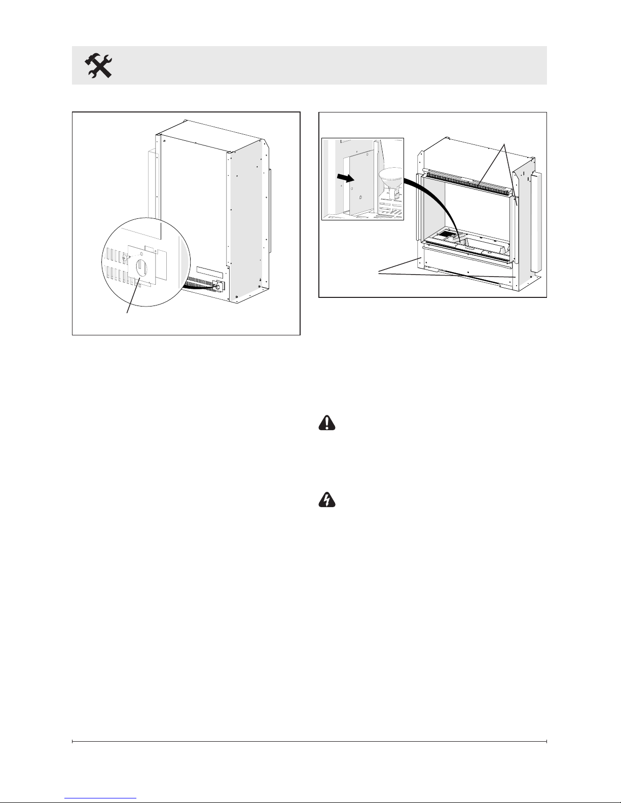
3. On the back of the unit remove
the cable clamp, by removing
the screw at the top (Figure 2).
4. Install a 3/8 in. (10 mm) or
1/2 in. (13 mm) cable connector, not included, suitable for
mounting in a 7/8 in. (22 mm)
hole, to the cable plate and
A
B
C
D
E
A B C D E
BOF4056
17.8in (451mm) 27.6in. (701mm) 10.0in. (255mm) 16.3in (413mm) 15.6in. (395mm)
BOF4068
17.8in (451mm) 32.4in. (823mm) 10.0in. (255mm) 16.3in (413mm) 20.4in. (517mm)
BOF6056
23.9in. (607mm) 27.6in. (701mm) 10.0in. (255mm) 22.4in (569mm) 15.6in. (395mm)
Page 8
8 www.dimplex.com
Installation
feed the supply cable through
the connector and secure.
5. Remove the 3 wires from
within the unit.
6. Connect the black wire (live)
from the unit to the black wire
from power supply.
7. Connect the white wire (neutral) from the unit to the white
wire from power supply.
8. Connect the green wire
(ground) from the unit to the
green wire from power supply.
9. Place all connectors inside
the unit and secure the cable
clamp to unit. Ensure that the
cable clamp grips only the
jacket of service cable.
!
NOTE: Once the unit has been
fully installed there is an access
Figure 3
panel in the water reservoir cavity
where the wiring can be accessed
from the front following installation
(Figure 3).
10. Install the unit into the roughed
in framing.
CAUTION: When inserting
the unit take care not to damage
or pinch any of the power cables
that are concealed in the wall.
WARNING: Ensure the power
wiring is not installed so that it
is pinched or against a sharp
edge and ensure that the power wiring is stored or secured
to avoid tripping or snagging to
reduce the risk of re, electric
shock or injury to persons.
11. Secure the unit to the framing
through the side anges with
the provided 8 screws (Figure
3).
Side
Flanges
Trim
Figure 2
Cable Plate
Page 9
9
?
?
>88cm
2
?
?
>88cm
2
>14 in
2
(>88 cm2)
>14 in
2
(>88 cm2)
>14 in
2
(>88 cm2)
Wiring
Figure 4
Installation
12. Reinstall the dust panel that
came installed in the rebox
opening.
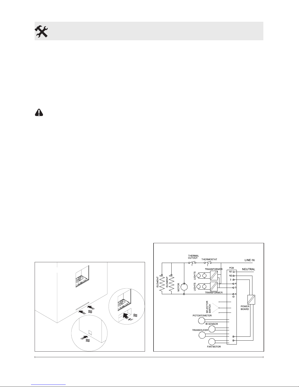
13. Finish surrounding wall. There
are 3 different options for nishing the wall:
CAUTION: Do not remove the
trim around the opening of the
unit (Figure 3).
• Permanent- install drywall
right up to the ange that surrounds the opening (Figure 4).
!
NOTE: An air inlet that is a
minimum of 14 in2 (88 cm2) is
required for optimum mist production, for minimum dimensions
(Figure 4).
• SemiPermanent- nish
around edge using ashing
material (not included).
• Flexible- create opening big
enough to access mounting
anges and a false front that
can be removed.
Bathroom Installation
This rebox must be protected
by a GFI circuit. If a receptacle
is used it must be readily accessible.
To prevent electrical shock this
unit is an electrical appliance
that is not watertight and must be
installed as to prevent water from
entering the unit. This unit must
be installed away from showers,
tubs, etc. Never locate replace
where it may fall into a bathtub or
other water containers. Keep towels and other combustible materials 3 feet (0.9 m) away from the
front of the unit.
Page 10
10 www.dimplex.com
Log
Media
Removable Rell
Container
Light
Bulbs
Assembly
Figure 5
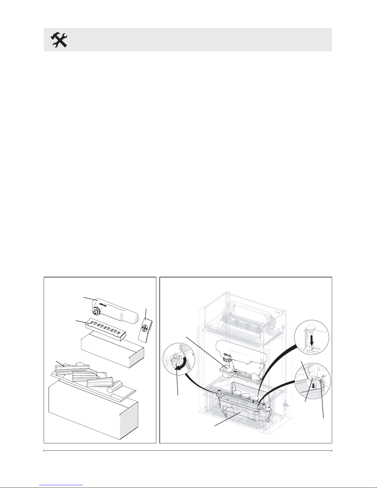
1. Carefully unpack all of the
components from the box.
(Figure 5)
2. Remove top cover by turning
the retaining tabs on both
ends of the water reservoir.
(Figure 6)
3. Install the light bulbs by
aligning the pins on the bulbs
and the xture and pressing
down until they are fully
inserted. (Figure 7)
4. Install the transducer so that
it is sitting level in the circular
holding area in the reservoir.
!
NOTE: The transducer is
packed in the water reservoir and
wrapped to protect it during shipping.
5. Orient transducer wire so that
it does not sit directly above
the emitter and the wire
passes through the slot in the
side of the tank. (Figure 6)
6. Reinstall the top cover and
ensure both retaining tabs
have been turned so that they
are pointing inwards.
7. Fill and install the Rell
Container.
!
NOTE: Normal tap water can
be used in the Optimyst® as long
as the tap water is not considered
to be hard water. In the event
Top
Cover
Figure 6
Transducer
Emitter
Wire Slot
Remote
Control
Retaining
Tabs
Water
Reservoir
Page 11

11
Assembly
your tap water is hard, you may
use softened water or distilled
water with 1/8 tsp of salt (0.5
mL) added to the water reservoir.
(The addition of additional salt
should only be used when you
notice that the unit is not producing mist as expected.)
!
NOTE: During initial
installation, the Rell Container
should be relled after the
Reservoir has lled to ensure the
maximum operating time.
8. Install the media tray and
arrange the log media on top.
Page 12
12 www.dimplex.com
Operation
!
NOTE: When the engine is
used in an environment where
background noise is very low, it
may be possible to hear a sound
which is related to the operation
of the ame effect. This is normal
and should not be a cause for
concern.
!
NOTE: Always ensure that
the appliance is xed to the framing in a level position.
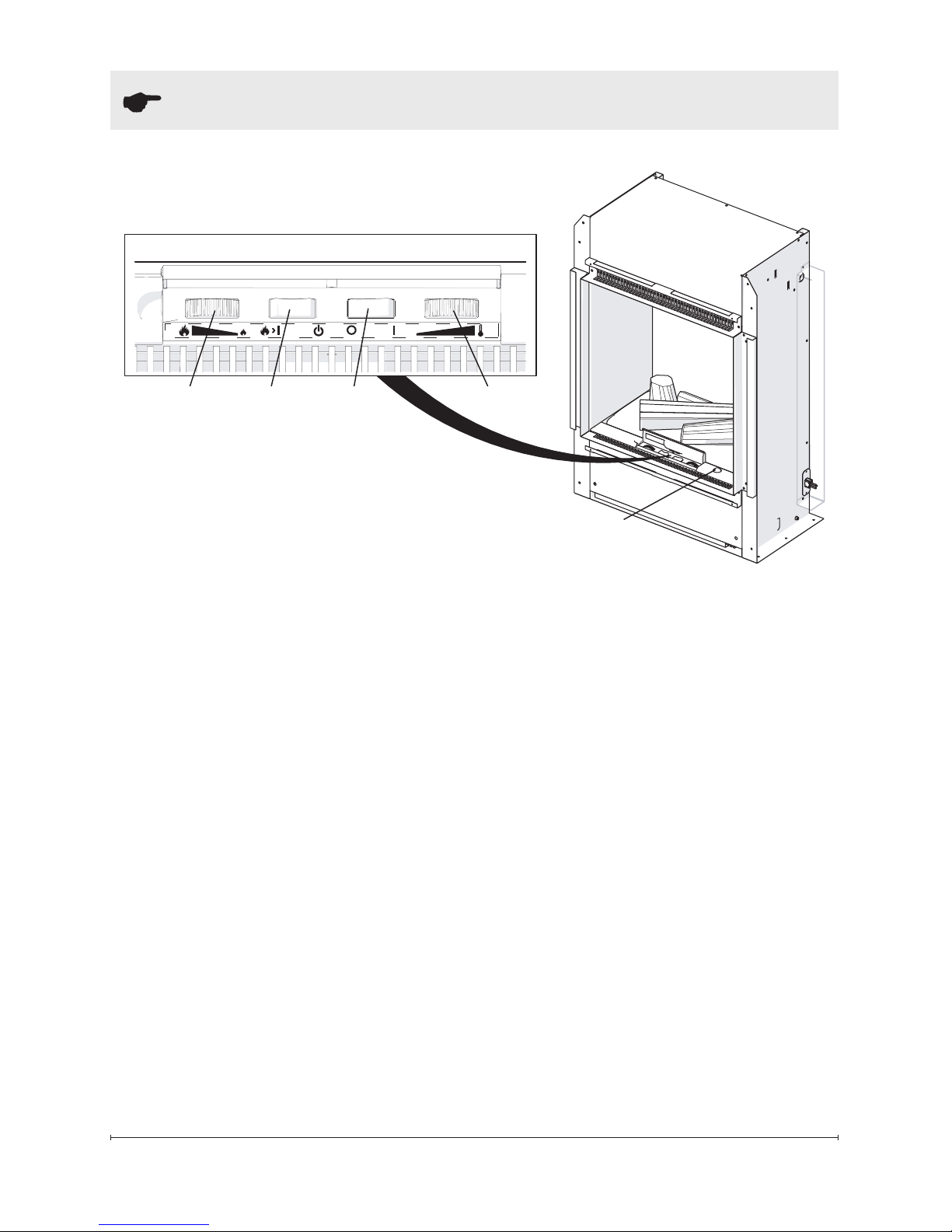
The manual controls for the unit
are located below the control
cover infront of the log grate
(Figure 7).
A. On/Off Switch
Supplies power to the engine.
B. Thermostat Control
To adjust the temperature to your
individual requirements, turn the
thermostat control backwards
all the way to turn on the heater.
When the room reaches the
desired temperature, turn the
thermostat knob forward until you
hear a click. Leave thermostat in
this position to maintain the room
temperature at this setting. For
additional heat, turn clockwise
until you hear the click again and
the heater will turn on.
C. Mode Selector Switch
Press once to turn on the ame
effect. This will be indicated by an
audible “beep”. Although the lights
turn on immediately it will take 30
seconds before the ame effect
starts.
• Press again to give ame effect and full heat. This will be
indicated by two “beeps”.
B
ACD
Figure 7
Remote Control
Sensor
Page 13

13
• Press again to return to ame
effect only. This will be indicated by one “beep”.
• Press to put re in to
standby mode. This will be
indicated by one “beep”.
D. Flame Intensity Control
Adjusts the intensity of the ame
and smoke effect when the heater
has been activated.
Turning the control knob clockwise decreases the intensity of
the ame and smoke effect. Turning the control counterclockwise
will increase the ame and smoke
effect.
!
NOTE: Give the ame genera-
tor some time to react to changes
you may make on the ame
control knob.
!
NOTE: When the water tank is
empty the unit will turn off after 30
seconds. See instructions under
Maintenance Section for relling tank. When this procedure is
complete, the main lamps will illuminate but it will take 30 seconds
before the ames return.
Resetting the Temperature
Cutoff Switch
Should the heater overheat, an
automatic cut out will turn the
replace off and it will not come
back on without being reset. It
can be reset by switching the On/
Off Switch to Off and waiting ten
(10) minutes before switching the
unit back on.
CAUTION: If you need to con-
tinuously reset the heater, unplug
the unit and call Dimplex North
America Limited at 1-888-3467539 for technical support. Please
have your model and serial number ready when calling.
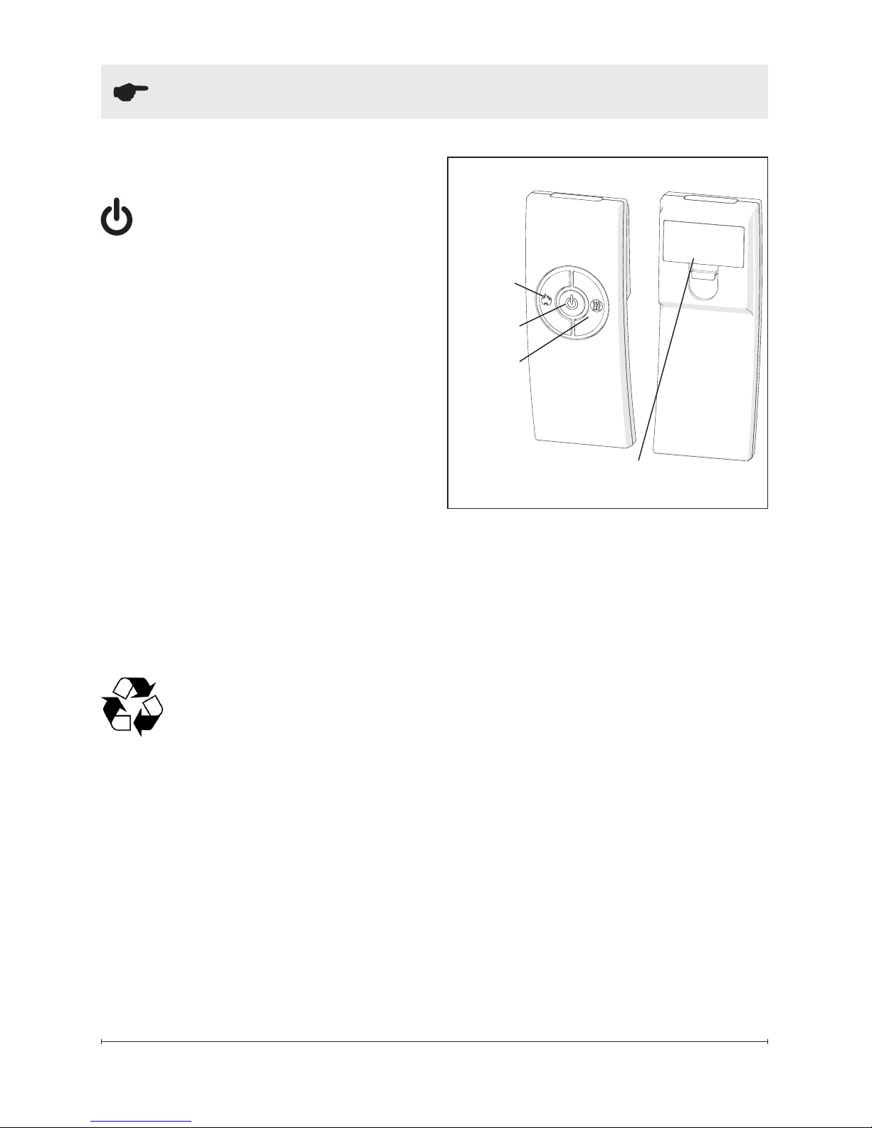
Remote Control
The On/Off Switch must be in the
‘ON’ ( I ) position in order for the
remote control to operate. There
are 3 buttons on the remote control. (Figure 8)
!
NOTE: To operate cor-
rectly the remote control must
be pointed towards the remote
control sensor.
The remote control functions are
as follows:
Press once to turn on Flame
effect only. This will be indicated by one beep.
Press once to turn on Full
heat and Flame effect. This
will be indicated by two
Operation
Page 14
14 www.dimplex.com
Battery Cover
Figure 8
Standby
Button
Flame
Button
beeps.
Standby - This will be indi-
cated by one beep.
!
NOTE: Once the mist has
been activated, the unit will have
to be turned Off, using either the
momentary button, on the unit,
or the Off button on the remote
control, then back on to return
to Level 1 - Logs and Light only
operation.
Battery Replacement
To replace the battery:
1. Slide battery cover open on
the remote control (Figure 8).
2. Install two 1.5 Volt (AAA) battery in the battery holder.
3. Close the battery cover.
Battery must be recycled
or disposed of properly.
Check with your Local
Authority or Retailer for recycling
advice in your area.
Operation
Heat
Button
Page 15

15
WARNING: Disconnect power
before attempting any maintenance or cleaning to reduce
the risk of re, electric shock
or damage to persons.
Filling the water tank
When the water tank is empty,
the ame effect shuts off and you
will hear 2 audible beeps, follow
these steps.
CAUTION: Allow at least ve
minutes for components to cool
before disassembling the unit to
rell.
1. Turn the On/Off switch to the
off position (0) (Figure 7)
2. Gently remove the log media
and place it carefully on the
ground.
3. Remove the rell container by
lifting upwards and outwards.
4. Rell the container with tap
water.
!
NOTE: Normal tap water can
be used in the Optimyst® as long
as the tap water is not considered
to be hard water. In the event
your tap water is hard, you may
use softened water or distilled
water with 1/8 tsp of salt (0.5
mL) added to the water reservoir.
(The addition of additional salt
should only be when you notice
that the unit is not producing mist
as expected.)
5. Screw the cap back on, do
notovertighten.
6. Return the rell container to
the sump, with the tank cap
facing down and the at side
of the tank facing outward.
7. Gently place the log media
back into position.
8. Turn the On/Off switch to the
off position (I). (Figure 7)
If you do not intend on using
the unit for longer than 2 weeks,
empty and drain the unit of water,
and dry all of the water containing
components.
Replacing the Light bulbs
If a large amount of the smoke
appears grey or colourless it may
be that one or more of the light
bulbs have burnt out.
CAUTION: Allow at least
twenty minutes for light bulbs
to cool before touching bulbs to
avoid accidental burning of skin.
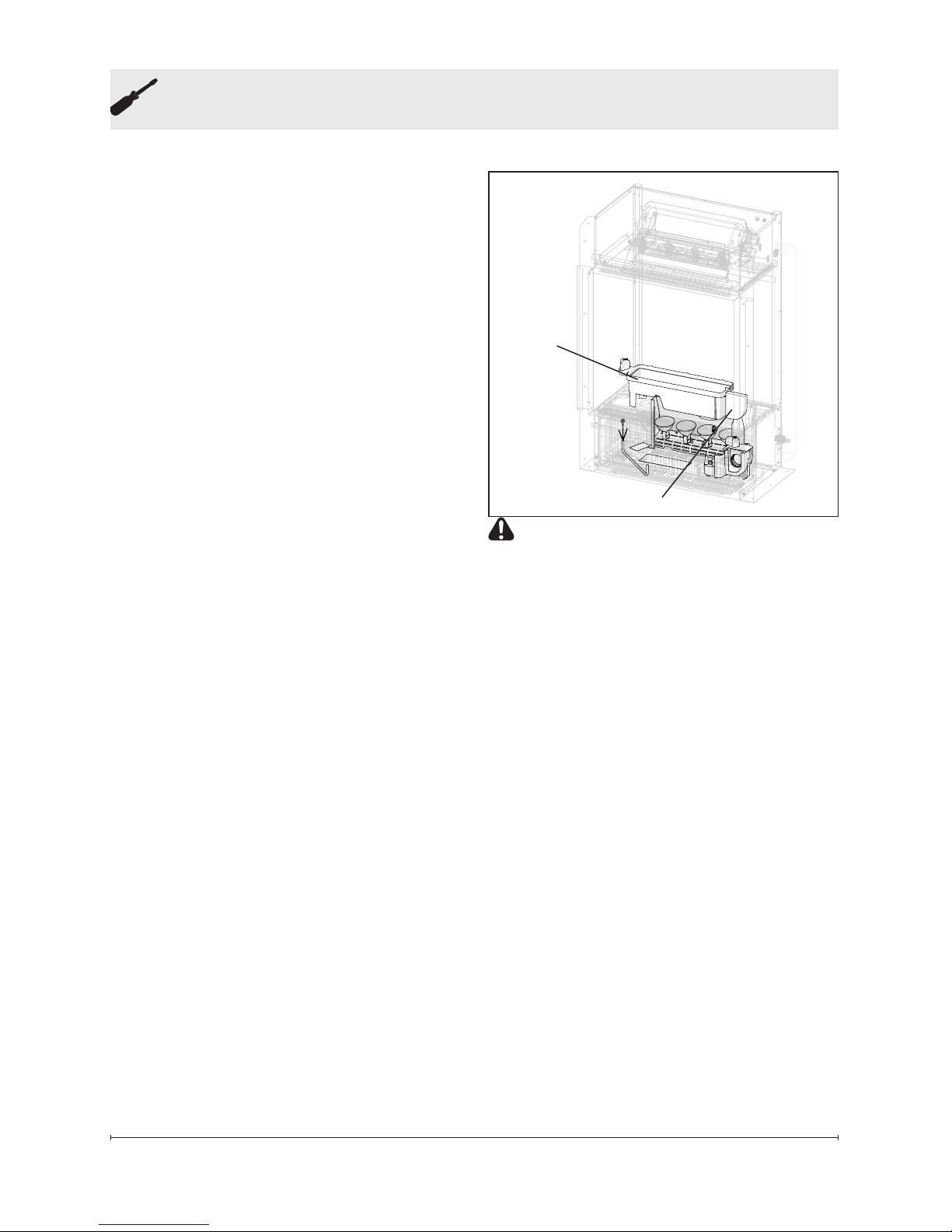
1. Leaving the ame effect on,
remove the log media and
water tank (Figure 9) and lift
out the top cover (Figure 6)
2. View the lamps from a distance in front of the re and
observe which lamp needs to
Maintenance
Page 16
16 www.dimplex.com
Maintenance
Figure 9
be changed.
3. Turn the unit off, and unplug
the engine.
4. Leave the appliance for 20
minutes to allow the lamps to
cool down before removing
them.
5. Remove the water tank and
sump (Figure 9) by lifting upwards and placing to the side.
6. Remove the defective bulb,
by gently lifting vertically and
disengaging the pins from the
lamp holder.
!
NOTE: Replacement light
bulbs can be obtained by contacting Dimplex Customer Service at
1-888-346-7539.
7. Carefully insert the two pins
of the new bulb into the two
holes in the lamp holder.
Push lamp rmly in place.
8. Replace the top cover, rell
container and log media.
Cleaning
It is recommended that all of the
components that contain water
are cleaned with soap and water
on a biweekly basis. A small
brush has been included to assist
in cleaning difcult items/areas,
i.e. the transducer.
Sump
Filter
CAUTION: Do not put plastic
components in the dishwasher.
Filter Cleaning
The air lter can be removed
and gently rinsed with water to
clean and dried on a towel before
reinstalling.
!
NOTE: Replace the lter so
that the course black lter is facing the front of the engine.
Surface Cleaning
Use a warm damp cloth only to
clean surfaces of the engine. Do
not use abrasive cleaners.
!
NOTE: If you need to move
the unit ensure that all of the components that contain water have
been emptied before relocating.
Page 17

17
Two Year Limited Warranty
Products to which this limited warranty
applies
This limited warranty applies to the following models of your newly purchased
Dimplex Optimyst® Pro and to newly
purchased Dimplex replace surrounds
(mantels) and trims. This limited warranty applies only to purchases made in
any province of Canada except for Yukon
Territory, Nunavut, or Northwest Territories
or in any of the 50 States of the USA (and
the District of Columbia) except for Hawaii
and Alaska. This limited warranty applies
to the original purchaser of the product
only and is not transferable.
Products excluded from this limited warranty
Light bulbs are not covered by this limited
warranty and are the sole responsibility of
the owner/purchaser. Products purchased
in Yukon Territory, Nunavut, Northwest
Territories, Hawaii, or Alaska are not
covered by this limited warranty. Products
purchased in these States, provinces, or
territories are sold AS IS without war-
ranty or condition of any kind (including,
without limitation, any implied warranties
or conditions of merchantability or tness
for a particular purpose) and the entire risk
of as to the quality and performance of the
products is with the purchaser, and in the
event of a defect the purchaser assumes
the entire cost of all necessary servicing
or repair.
What this limited warranty covers and for
how long
Products, other than replace surrounds
(mantels) and trims, covered by this
limited warranty have been tested and
inspected prior to shipment and, subject
to the provisions of this warranty, Dimplex
warrants such products to be free from
defects in material and workmanship for a
period of 2 years from the date of the rst
purchase of such products.
Dimplex replace surrounds (mantels) and
trims covered by this limited warranty have
been tested and inspected prior to shipment and, subject to the provisions of this
warranty, Dimplex warrants such products
to be free from defects in material and
workmanship for a period of 1 year from
the date of rst purchase of such products.
The limited 2 year warranty period for
products other than replace surrounds
(mantels) and trims and the limited 1 year
warranty period for replace surrounds
(mantels) and trims also applies to any
implied warranties that may exist under
applicable law. Some jurisdictions do not
allow limitations on how long an implied
warranty lasts, so the above limitation may
not apply to the purchaser.
What this limited warranty does not cover
This limited warranty does not apply to
products that have been repaired (except
by Dimplex or its authorized service
representatives) or otherwise altered. This
limited warranty does further not apply
to defects resulting from misuse, abuse,
accident, neglect, incorrect installation,
improper maintenance or handling, or
operation with an incorrect power source.
What you must do to get service under
this limited warranty
Defects must be brought to the attention of
Dimplex Technical Service by contacting
Dimplex at 1-888-DIMPLEX (1-888-346-
7539), or 1367 Industrial Road, Cambridge Ontario, Canada N1R 7G8. Please
have proof of purchase, catalogue/model
and serial numbers available when calling.
Limited warranty service requires a proof
of purchase of the product.
What Dimplex will do in the event of a
defect
In the event a product or part covered by
this limited warranty is proven to be defective in material or workmanship during (i)
the 2 year limited warranty period for products other than replace surrounds (mantels) and trims, and (ii) the 1 year limited
warranty period for surrounds (mantels)
and trims, you have the following rights:
• Dimplex will in its sole discretion either
Warranty
Page 18

18 www.dimplex.com
repair or replace such defective product or part without charge. If Dimplex
is unable to repair or replace such
product or part, or if repair or replacement is not commercially practicable
or cannot be timely made, Dimplex
may, in lieu of repair or replacement,
choose to refund the purchase price
for such product or part.
• Limited warranty service will be
performed solely by dealers or service
agents of Dimplex authorized to provide limited warranty services.
• For products other than surrounds
(mantels) and trims, this 2 year lim-
ited warranty entitles the purchaser to
on-site or in-home warranty services.
Accordingly, Dimplex will be responsible for all labour and transportation associated with repairing or replacing the
product or part except as follows: (i)
charges which may be levied for travel
costs incurred to travel to the purchaser’s site where the product is located
if the purchaser’s site is beyond 30
miles (48 km) from the closest service
depot of Dimplex’s dealer or service
agent; and (ii) the purchaser is solely
responsible for providing clear access
to all serviceable parts of the product.
• For surrounds (mantels) and trims,
this 1 year limited warranty does
not entitle the purchaser to on-site
or in-house warranty services. The
purchaser is responsible for removal
and transportation of the surrounds
(mantels) and trims (and any repaired
or replacement product or part) to and
from the authorized dealer’s or service
agent’s place of business. On-site
or in-home services for surrounds
(mantels) and trims may be performed
at the purchaser’s specic request
and expense at Dimplex’s then-current
rates for such services. Dimplex
will not be responsible for, and this
limited warranty shall not include, any
expense incurred for installation or
removal of the surrounds (mantels)
or trims or any part thereof (or any
replacement product or part) including,
without limitation, all shipping costs
and transportation costs to and from
the authorized dealer’s or service
agent’s place of business and all
labour costs. Such costs shall be the
purchaser’s responsibility.
What Dimplex and its dealers and service
agents are also not responsible for:
IN NO EVENT WILL DIMPLEX, OR ITS
DIRECTORS, OFFICERS, OR AGENTS,
BE LIABLE TO THE PURCHASER OR
ANY THIRD PARTY, WHETHER IN CON-
TRACT, IN TORT, OR ON ANY OTHER
BASIS, FOR ANY INDIRECT, SPECIAL,
PUNITIVE, EXEMPLARY, CONSEQUENTIAL, OR INCIDENTAL LOSS, COST,
OR DAMAGE ARISING OUT OF OR
IN CONNECTION WITH THE SALE,
MAINTENANCE, USE, OR INABILITY TO
USE THE PRODUCT, EVEN IF DIMPLEX
OR ITS DIRECTORS, OFFICERS, OR
AGENTS HAVE BEEN ADVISED OF
THE POSSIBILITY OF SUCH LOSSES,
COSTS OR DAMAGES, OR IF SUCH
LOSSES, COSTS, OR DAMAGES ARE
FORESEEABLE. IN NO EVENT WILL
DIMPLEX, OR ITS OFFICERS, DIRECTORS, OR AGENTS BE LIABLE FOR
ANY DIRECT LOSSES, COSTS, OR
DAMAGES THAT EXCEED THE PURCHASE PRICE OF THE PRODUCT.
SOME JURISDICTIONS DO NOT ALLOW
THE EXCLUSION OR LIMITATION OF
INCIDENTAL OR CONSEQUENTIAL
DAMAGES, SO THE ABOVE LIMITATION
OR EXCLUSION MAY NOT APPLY TO
THE PURCHASER.
How State and Provincial law apply
This limited warranty gives you specic
legal rights, and you may also have other
rights which vary from jurisdiction to jurisdiction. The provisions of the United Nations Convention on Contracts for the Sale
of Goods shall not apply to this limited
warranty or the sale of products covered
by this limited warranty.
Warranty
Page 19

19
Replacement Parts
Remote Control . . . . . . . . . . . . . . . . . . . . . . . . . . . . . . . . . . . . . 9600385600RP
Remote Control Receiver .............................9600580100RP
Log Media Assembly (BOF40XX) .......................9600720100RP
Log Media Assembly (BOF60XX) .......................9600730100RP
Heating Assembly (with cutout) . . . . . . . . . . . . . . . . . . . . . . . . . 9600680100RP
Light Holder Assembly. . . . . . . . . . . . . . . . . . . . . . . . . . . . . . . . 9600610100RP
Removable Rell Container with Cap ....................0441440100RP
Cap for Rell Container . . . . . . . . . . . . . . . . . . . . . . . . . . . . . . . 0441440300RP
Top Cover Assembly .................................9600670100RP
Water Reservoir (Sump) ..............................0441380100RP
Fan Assembly ......................................5300300100RP
Fan Housing Assembly ...............................9600540100RP
Fan Filter ..........................................8600300100RP
Transducer ........................................3800040100RP
On/Off Switch ......................................9600383500RP
3-Position Switch. . . . . . . . . . . . . . . . . . . . . . . . . . . . . . . . . . . . 9600383600RP
Transformers . . . . . . . . . . . . . . . . . . . . . . . . . . . . . . . . . . . . . . . 9600690100RP
Potentiometer ......................................9600640100RP
Thermostat Assembly ................................9600620100RP
Control Knob .......................................9600630200RP
Power Board .......................................9600590100RP
IR Receiver with Lens ................................9600630200RP
Light Bulbs. . . . . . . . . . . . . . . . . . . . . . . . . . . . . . . . . . . . . . . . . . . . . . . . RB400
© 2014 Dimplex North America Limited
Dimplex North America Limited
1367 Industrial Road
Cambridge ON
Canada N1R 7G8
 Loading...