

Page 1
Installation and Operating Instructions
•
•
•
•
•
•
•
•
•
Installation Instructions
Ensure that all packing items are removed (read any warning
labels carefully).
Retain all packing until installation is complete.
Safety Warnings
When using electrical appli ances, Basic precautions
should always be followed to reduce the risk of fire,
electrical shock and injury to persons, including the
following:
If the appliance is damaged, check with the supplier
before installation and operation
Do not use outdoors.
Do not use in the immediate surroundings of a bath,
shower or swimming pool.
Do not locate the heater immediately below a fixed
socket outlet or connection box.
Do not cover the heater. Do not place material or
garments on the heater, or obstruct the air circulation
around the heater, for instance by curtains or furniture,
as this could cause overheating and a fire risk.
Do not leave young children or the infirm unsupervised
in the vicinity of the heater.
Ensure that furniture, curtains or other combustible
material are positioned no closer than 1 meter from the
heater.
Introduction
In the event of a fault unplug the heater.
Unplug the heater when not required for long periods.
This fire incorporates a flame effect, which can be used with
or without heating, so that the comforting effect may be
enjoyed at any time of the year. The flame effect is provided
by low wattage motors and two 40 watt lamps. Using the
flame eff ect on its own, therefore, requires little electricity.
The manual controls and the remote control are located
behind the firebox door. A Choice of 1kw or 2kw
thermostatically controlled heat output is provided by the fan
heater, which is concealed beneath the unit.
• The appliance must be positioned so that the plug is
accessible.
This model is designed to be free standing and is normally
positioned against a wall.
• If the supply cord is damaged it must be replaced by the
manufacturer or service agent or a similarly qualified
person in order to avoid a hazard.
IMPORTANT: THESE INSTRUCTIONS SHOULD BE READ CAREFULLY AND RETAINED FOR FUTURE REFERENCE
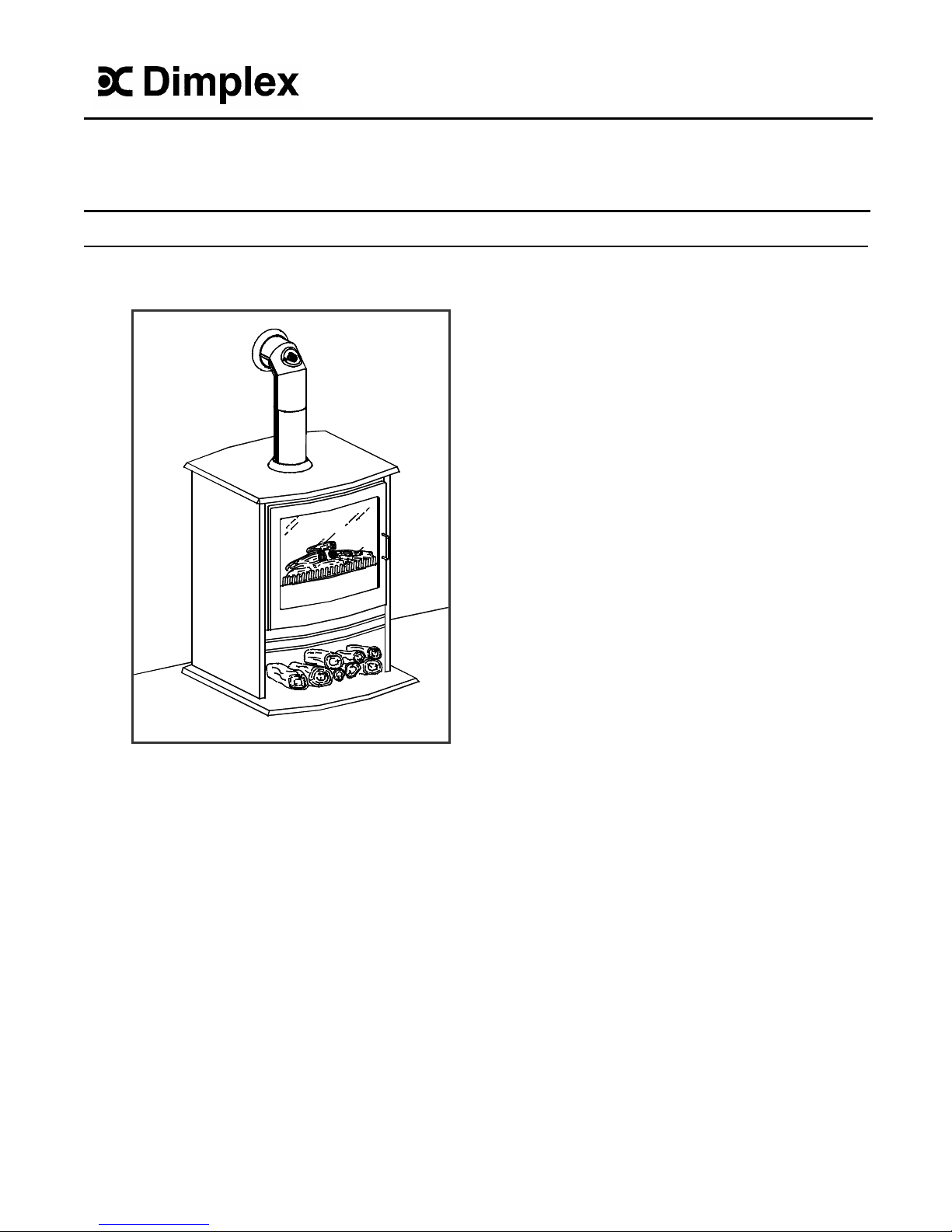
Dimplex Americana Model:AMR20R
08/18614/0
Focal Point Fire with Optiflame Elite ®*
incorporating 2kw Fan Heater with Remote Control
Page 2
Preperation for Use
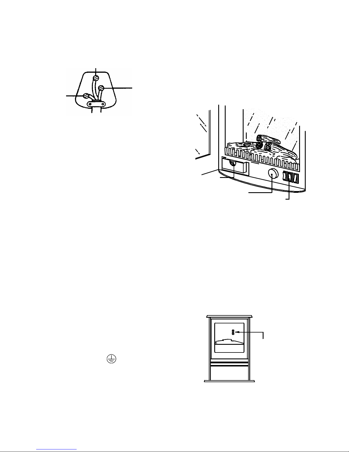
Neon's for i ndicati ng
operat i on l evel
Fig. 1
This heater must be used on an AC ~ supply only and the
voltage marked on the heater must correspond to the supply
voltage.
For your convenience, the heater is fitted with a rewirable
plug incorporating a 13 amp fuse. In the event of replacing
the fuse supplied, a 13 amp fuse approved by ASTA to BS
1362 must be used.
IMPORTANT: if the plug is not suitable for your socket, the
13 amp plug should be removed and the appropriate plug
fitted in accordance with the wiring instructions below.
Note: When either the remote control or the manual controls
are used, the neon’s will come on for 3 seconds indicating
the relevant setting.
(see fig.2)
BLUE - NEUTRAL
BROWN - LIVE
Fig. 2
GREEN AND YELLOW - EARTH
As the colours of the wires in the mai ns lead may not
correspond with the coloured markings identifying the
terminals in your plug, proceed as follows:
Connect the BROWN wire to the terminal marked L or
coloured RED.
Connect the BLUE wire to the terminal marked N or coloured
BLACK.
Connect the GREEN AND YELLOW wire to the terminal
marked E or by the earth symbol Or coloured GREEN
or GREEN AND YELLOW.
If a 3-pin 15 amp plug is used this should be protected by a
15 amp fuse either in the plug or adapter, or the distribution
board.
If in doubt consult your electrician.
Operation
The controls are located behind the door see Fig1.
To operate the stove either manually or by using the remote
control, the standby switch must first be turned on. (see Fig.
4).
The red indicator mark on the switch will be visible when it is
turned on.
E. Earth
Green - Yellow
L. Live
Brown
N. Neutral
Blue
Wiring a 15 amp plug
WARNING: THIS APPLIANCE MUST BE EARTHED
Remote Control
located in pocket
for details on
controls see
Fig. 4
Thermostat Knob
Page 3

Setting Manual or Remote Operation Indication
Flam e effect Press the ‘ON’ button once Bottom Neon
Flame effect & 1kW heat setting Press the ‘ON’ button again Bottom & Middle Neon
Flam e effect & 2kW heat setting Press the ‘ON’ button again All 3 Neon’s
To turn off any of the settings Press the ‘OFF’ button once.
To increase or decrease the brightness of the fuel effect use the buttons as shown in Fig. 4.
Fig.3
Fig.4
Manual or Remote Operation
1. Slide open the battery cover on the back of the
remote control
2. Install three AAA batteries into the remote control
(see Fig. 3)
3. Replace the battery cover.
Batteries
Remote Control Oper
Warning: it takes some tim
respond to the transmitter
Decrease Brightness
Off Button
Increase Brightness
On Button
Standby
Switch
OFF
ON
ation
e for the receiv
. Do not press th
er to
e buttons
more than once within two seconds for correct
operation.
Manual Controls
Note: The Standby Switch must be first
turned on to operate either the manual
or the remote controls.
Page 4

2
1
(
The product c omplies with the Eur opean Safety Standards EN60335-2-30 and the European St andard Electromagnetic Compatibility
EMC) EN55014, N60555- 2 and EN60555-3 which cover the essential requirements of EEC Directives 73/23 and 9/336
Glen Dimplex UK Limit ed UK customer hel p line (8.00AM – 6. 00PM Mon-Fri; 8.30AM-1.00PM Sat)
Millbr ook House
Grange Drive Customer Services: Tel. 0870 7270101
Hedge End Fax. 0870 7270102
Southampton e-mail www.customer.services@glendimplex.com
Hampshire. SO30 2DF Republic of Ireland Tel. 01 8424833
Thermostat operation
The thermostat controls the heat output according to the
room temperature. This ensures that the heater will not
produce heat unnecessarily when the room is warm.
To set the temperature you require, turn the thermostat knob
fully clockwise to ‘max’ position. When the room is warm
enough, turn the knob back slowly until the thermostat just
clicks off. The heater will now maintain your selected
temperature.
WARNING: ALWAYS DISCONNECT FROM THE
POWER SUPPLY BEFORE ATTEMPTING ANY
MAINTENANCE
Thermal Safety Cutout
A thermal safety cut-out is incorporated in the heater to
prevent damage due to overheating.
This can happen if the heat outlet were restricted in any way.
The heater will switch on once the obstruction has been
removed and the heater has cooled. If the cut-out continues
to operate intermittently, the heater should be switched off
and a service agent contacted.
Lamp replacement
To gain access to the lamps, open the door, remove the fuel
effect by first lifting it up (See Fig. 5.n )and then out.(See
Fig. 5.
o ).Carefully rotate the lamp anti-clockwise until it
comes out of its holder (See Fig. 6)
Replace the defective lamp with a 230V, 40W max, E14 SES
clear candle lamp, rotating the lamp clockwise in the holder
until it is fully home. Do not over tighten.
When refitting the fuel effect ensure it sits in behind the front
metal edge at the control panel.
Fig.5
Fig. 6
Cleaning & Maintainence
For general cleaning use a soft clean duster or, if necessary,
a damp cloth – never use abrasive cleaners
The fuel effect can be cleaned with a soft brush or vacuum
cleaner.
The glass viewing screen should be cleaned carefully with a
chamois leather. DO NOT use proprietary glass cleaners.
After Sales Service
Your product is guaranteed for one year from the date of
purchase.
We undertake to repair or exchange free of charge within this
period, any part, with the exception of a lamp bulb, found to
be defective due to a manufacturing fault.
All enquiries for service should be directed in the first
instance to the retailer from whom your product was
purchased.
Please do not initially return a faulty appliance or part of an
appliance to us as this may result in transit damage and/or
delay in providing service.
Let us know your difficulty quoting the model number and
series letter of the appl iance. We will then take the
appropriate action.
 Loading...