

Dimplex Danube DNB20, Lagan LAG20, Elba ELB20, Allegri ALG20 Installation And Operating Instructions Manual
Page 1
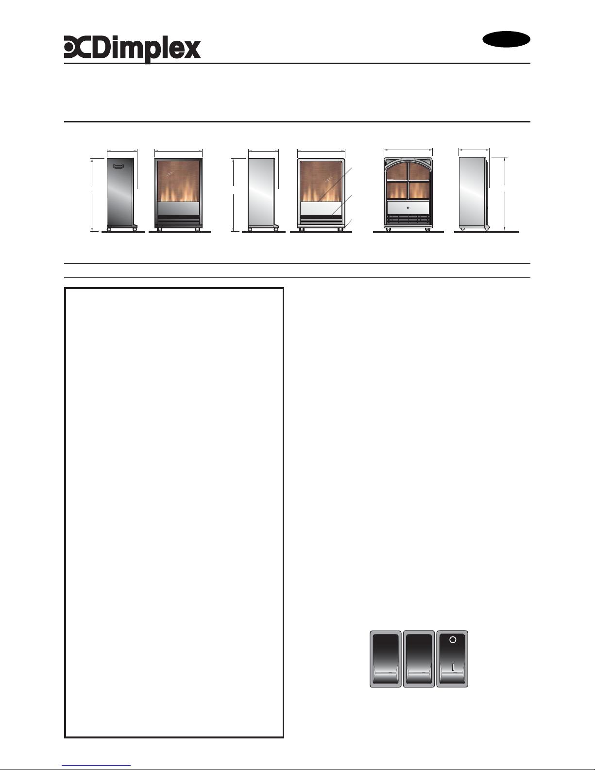
Dimensions
(millimetres)
Installation and Operating Instructions
08/18989/4 Issue 4
Danube Portastove Model: DNB20
Lagan Portastove Model: LAG20
Elba Portastove Model: ELB20
Allegri Portastove Model: ALG20
Important Safety Advice
When using electrical appliances, basic precautions
should always be followed to reduce the risk of fire,
electrical shock, and injury to persons, including the
following:
If the appliance is damaged, check with the supplier
before installation and operation.
Do not use outdoors.
Do not use in the immediate surroundings of a bath,
shower or swimming pool.
Do not locate the heater immediately below a fixed socket
outlet or connection box.
Do not cover the heater. Do not place material or
garments on the heater, or obstruct the air circulation
around the heater, for instance by curtains or furniture,
as this could cause overheating and a fire risk.
The appliance is not intended for use by young children
or infirm persons unless they have been adequately
supervised by a responsible person to ensure that they
can use the appliance safely.
Young children should be supervised to ensure they
do not play with the appliance.
Do not use this heater in series with a thermal control,
a program controller, a timer or any other device that
switches on the heat automatically, since a fire risk
exists when the heater is accidentally covered or
displaced.
Ensure that furniture, curtains or other combustible
material are positioned no closer than 1 metre from the
heater.
In the event of a fault unplug the heater.
Unplug the heater when not required for long periods.
Although this heater complies with safety standards,
we do not recommend its use on deep pile carpets or
on long hair type of rugs.
The appliance must be positioned so that the plug is
accessible.
If the supply cord is damaged it must be replaced by
the manufacturer or service agent or a similarly
qualified person in order to avoid a hazard.
Keep the supply cord away from the front of the heater.
Introduction
Unpack the heater carefully and retain the packaging for possible
future use, in the event of moving or returning the fire to your supplier.
These models are fitted with castors so they can moved from room
to room with ease, and are normally positioned against a wall.
A choice of 1kW or 2kW heat output is provided by the fan heater,
which is located at the bottom of the unit.
Before connecting the heater check that the supply voltage is the
same as that stated on the heater.
Please note: Used in an environment where background noise is
very low, it may be possible to hear a sound which is related to the
operation of the flame effect. This is normal and should not be a
cause for concern.
Electrical connection
WARNING – THIS APPLIANCE MUST BE EARTHED
This heater must be used on an AC ~ supply only and the voltage
marked on the heater must correspond to the supply voltage.
Before switching on, please read the safety warnings and operating
instructions.
Operation
The unique flame effect may be enjoyed whether or not the heating
elements are in operation.
Controls
The heater controls are located behind the flap on the front of the
heater. (see Fig. 1).
Three switches provide a choice of heat settings. A switch is in the
ON position when the side with the markings on (i.e. I , I , or II ) is
pushed in.
Fig. 1
Fig. 2
IMPORTANT: THESE INSTRUCTIONS SHOULD BE READ CAREFULLY AND RETAINED FOR FUTURE REFERENCE
1
2
3
I
II
II
432
662
275
662
275
432
662
275
432
Danube (Black)
Lagan (Silver)
Elba Allegri
castors
heat
outlet
controls
located
behind
flap
AUS/NZ
Page 2
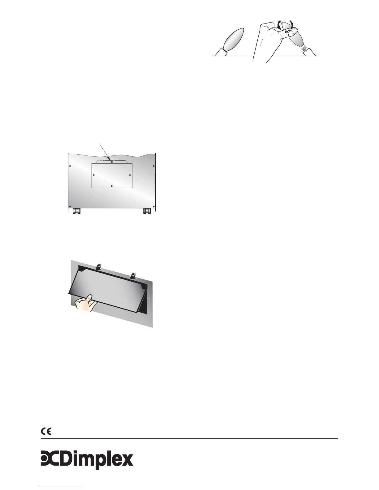
Fig. 3
Switch 1 ( I ) Controls the electricity supply to the heater and
flame effect
Note: This switch must be in the ON ( I ) position
for heater to operate with or without heat
Switch 2 ( I ) Provides 1kW heat output
Switch 3 ( II ) Provides 2kW output with switch 2
Maintenance
WARNING – BEFORE UNDERTAKING ANY MAINTENANCE OR
CLEANING REMOVE PLUG OR DISCONNECT FROM THE
ELECTRICITY SUPPLY.
Lamp Replacement
Two lamps are located behind the back panel as indicated in Fig. 3.
To gain access to the lamps, the four screws which secure the back
panel, must be removed. Remove and slide out panel as indicated in
Fig. 4.
Remove the defective lamp by unscrewing it as shown -see Fig. 5.
Replace with a 60W E14 SES Clear Candle lamp.
Take care not to over-tighten the lamp. Refit the back panel and
secure with the four screws.
Thermal Safety Cut-out
The built-in overheat cut-out switches of the appliance automatically
in the event of a fault. Switch off the appliance or disconnect the
mains plug from the socket. After a short cooling down phase, the
appliance is ready for use again. If the fault should occur again, see
your local dealer.
WARNING: In order to avoid a hazard due to inadvertent resetting of
the thermal cut-out, this appliance must not be supplied through an
external switching device, such as a timer, or connected to a circuit
that is regularly switched on and off by the utility.
Cleaning
For general cleaning use a soft clean duster – never use abrasive
cleaners. The viewing screen should be cleaned carefully with a
soft cloth. DO NOT use proprietary glass cleaners.
After Sales Service
Please see the separate Warranty leaflet for details of your
Warrantee & after sales service including contact details.
Should you require after sales service, please get in touch with
the supplier through whom you purchased the appliance, or the
contact number on your Warranty leaflet.
Fig. 5
four screws on
removable back
panel
Fig. 4
The product complies with the Australian/New Zealand Safety Standards AS/NZ S 335.2.30:1997 and 2002 Part 1 also the European Standard ElectromagneticCompatibility (EMC) EN 55 0141:1993, EN 61000-3-2:1995, EN 61000-3-3:1995, EN 55 014-2:1997. These cover the essential requirements of EEC Directive 2006/95/EC and 2004/108/EC.
Specification subject to change without prior notice
 Loading...