

Page 1
Architectural Heaters
AF20 Series
IMPORTANT INSTRUCTIONS
When using electrical appliances, basic precautions should
always be followed to reduce the risk of re, electric shock,
and injury to persons, including the following:
1. Read all instructions before using the heater.
2. The heater is hot when in use. To avoid burns, do not let
bare skin touch hot surfaces. The trim around the heater
outlet becomes hot during heater operation. Keep combustible materials, such as furniture, pillows, bedding,
papers, clothes, and curtains at least 3 ft (0.9 m) from the
front of the unit and keep them away from the sides and
rear.
3. Extreme caution is necessary when any heater is used
by or near children or invalids and whenever the unit is
left operating and unattended.
4. Do not operate any heater after it malfunctions. Discon-
nect power at the service panel and have the heater inspected by a reputable electrician before reusing.
5. Do not use outdoors.
6. To disconnect the unit, turn the controls off, and then
switch off at main power supply panel.
7. Do not locate these heaters below any electrical convenience receptacles.
8. Do not install these heaters against combustible, low
density cellulose bre surfaces.
9. Do not insert or allow foreign objects to enter any ventilation or exhaust opening as this may cause an electric
shock or re, or damage to the heater.
10. To prevent a possible re, do not block air intake or exhaust in any manner.
11. All electrical heaters have hot and arcing or sparking
parts inside. Do not use in areas where gasoline, paint,
or ammable liquids are used or stored.
12. Do not modify this heater. Use it only as described in
this manual. Any other use not recommended by the
manufacturer may cause re, electric shock or injury to
persons.
SAVE THESE INSTRUCTIONS
Installation Instructions
WARNING: Wiring procedures and connections should
be in accordance with the National Electric Code (NEC &
CEC) and local codes.
WARNING: To reduce the risk of re, do not store or use
gasoline or other ammable vapors or liquids in the vicinity of
the heater.
CAUTION: High temperature, risk of re, keep electrical
cords, drapery, furnishings, and other combustibles at
least 3 feet (0.9 m) from the front of the heater.
Recommendations for Locating Drapes and Furniture
near Heaters
For most satisfactory operation of the baseboard heaters and
minimum effect on drapes and furniture, the following recommendations should be observed:
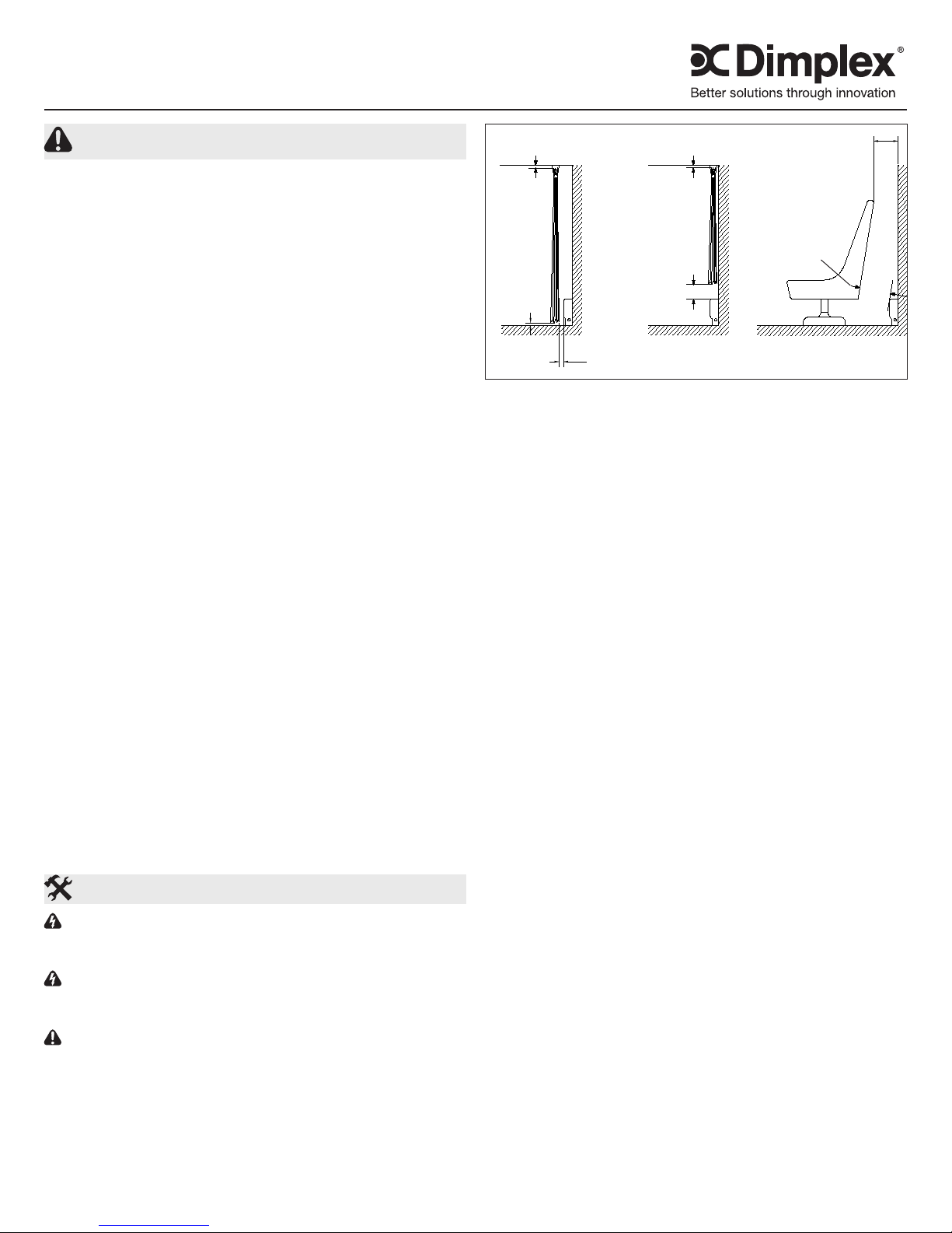
1.5 in (3.81 cm)
min
1.5 in
(3.81 cm)
min
3 in (7.62 cm)
min
1. Hang drapes so that, in use, they extend below the center line of the heater, but with at least 1.5 inches clearance from the nished oor covering (such as carpet, if
used).
2. Hang drapes so that there is at least 3 inches between
the extreme front of the heater and the nearest fold of the
drapes in the folded back (opened drape) position.
3. Hang drapes so there is at least 1.5 inches between the
top of the drapes and the ceiling.
4. To be suitable for draperies located close to heaters,
material should not discolour nor distort dimensionally
(stretch or shrink) upon extended exposure (1000 hrs.) to
a temperature of 200º F (93º C).
!
NOTE: If drapes are to be cut off above a heater, they
should be cut off at least 6 inches above the top of the
heater and preferably more.
!
NOTE: Place furniture no closer then 3 inches from the
baseboard heater.
1.5 in (3.81 cm)
min
6 in (15.24 cm)
min
3 in (7.62 cm)
min
3 in (7.62 cm)
min
Wall Installation
1. Unpack the heater from the carton and remove the front
panel.
!
NOTE: The front panel screws are recessed at the bot-
tom of the front panel at each end of the heater.
2. Remove the desired terminal box covers and wire supply
knockouts from the terminal box area.
3. Determine the correct mounting height, and scribe or
snap a level line on the wall to maintain each heater back
plate in a horizontal alignment, when mounting.
!
NOTE: The front panel screws are recessed in the top
louvres at each end of the heater.
4. Mount the back plate to the wall using suitable fasteners
(provided by the customer) using the scribed line on the
wall to keep the heater level.
!
NOTE: Should the wall surface be uneven, secure the
heater back panel to the high spots. This will avoid a dis-
torted appearance.
5. Proceed to the wiring instructions.
7203110000R02
Page 2
Recessed Wall Installation
!
NOTE: The use of a Signature Series Trim kit is strongly
recommended when recessing the heater.
!
NOTE: A recess opening dimension of 20-1/2” high and
the length of the heater is required to install this heater.
!
NOTE: The heater may be recessed up to a depth of
5-5/8”.
1. Unpack the heater from the carton and remove the front
panel.
!
NOTE: The front panel screws are recessed at the
bottom of the front panel at each end of the heater.
2. Remove the desired terminal box covers and wire supply
knockouts from the terminal box area.
3. Use trim frame as a template to drill holes into the top,
bottom and sides of the heater using a 1/8” diameter drill
bit.
4. Secure the trim frame using the #8 screws provided with
the trim kit.
!
NOTE: The bottom trim may be omitted if the heater is to
be installed at oor level.
5. Prepare the wall recess opening to accept the heater.
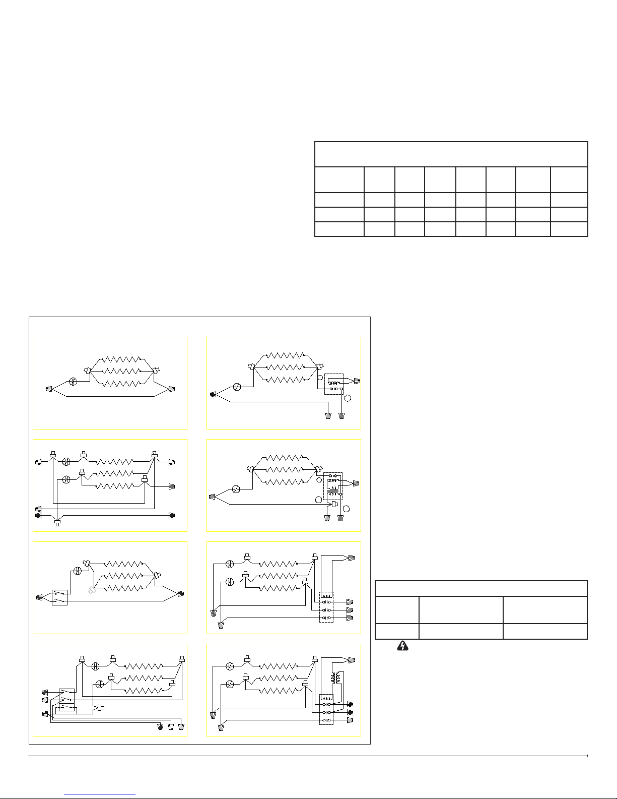
Wiring Diagrams
HEATER NO CONTROLS - 1 PH PARALLEL
ELEMENT
L1
LIMIT CONTROL
L2
HEATER NO CONTROLS - 3 PH DELTA
L1
LIMIT CONTROL
L2
L3
HEATER 2 POLE STAT - 1 PH PARALLEL
L1
L2
HEATER c/w 2 or 3 POLE STAT - 3 PH DELTA
L1
L2
L3
LIMIT CONTROL
STAT
STAT
RETURN WIRES
ELEMENT
RETURN WIRES
ELEMENT
RETURN WIRES
LIMIT CONTROL
RETURN WIRES
7106223000
ELEMENT
L1
L2
7106222200
L2
L1
L3
7106222500
7106222700
L2
L1
L1
L2
L3
HEATER LVD RELAY - 1 PH PARALLEL
LIMIT CONTROL
RETURN WIRES
HEATER LVC RELAY - 1 PH PARALLEL
LIMIT CONTROL
HEATER 3 POLE CONTACTOR - 3 PH DELTA
LIMIT CONTROL
HEATER 3 POLE CONTACTOR/TX - 3 PH DELTA
LIMIT CONTROL
REGLAGE DE LIMITE
ELEMENT
ELEMENT
RETURN WIRES
ELEMENT
RETURN WIRES
ELEMENT
RETURN WIRES
!
NOTE: Leave approximately 1/2” clearance to insert the
heater cabinet.
6. Secure the back plate into the recess opening using suit-
able fasteners (provided by customer).
7. Proceed to wiring instructions.
Wiring Instructions
Recommended minimum supply wire sizes are listed in the
table below:
MAXIMUM WATTS PER CIRCUIT USING 75 °C WIRE
(COPPER WIRE)
Rough in
Wire Size
14 1440 2496 2880 3324 4164 5760 7200
12 1920 3328 3840 4432 5552 7680 9600
10 2880 4992 5760 6648 8328 11520 14400
1. Run branch circuit wiring of proper voltage and wire size
to the location of the terminal box of the heater. (See
Chart)
!
NOTE: Supply wire entry is commonly made into one
heater. Through wiring (factory furnished) can be used
for connection to adjacent heaters.
RELAY
A
L1
7106223700
RELAY
A
B
L2
7106223200
24V
CONTACTOR
7106224000
24V
CONTACTOR
7106223500
120V 208V 240V 277V 347V 480V 600V
2. Wire all heaters and controls in accor-
dance with the appropriate wiring diagram.
!
NOTE: Sample wiring diagrams beside.
3. Wrap the supply ground wire around the
T2
T1
C
L2
green painted ground screw & tighten.
!
NOTE: When heaters are mounted end to
end, remove the nished end plate, install
a chase nipple and locknut in the terminal
box to ensure grounding continuity and to
protect the wiring.
Where headers are spaced apart, remove
the nishing end plate, and use rigid conduit
T2
(provided by customer) for through wiring and
T1
ground continuity. Do not exceed the allowable
C
L1
number of conductors allowed by the National
Electric Code.
4. Do a nal and complete check of all wiring
T2
T1
then replace the terminal box covers being
careful not to pinch any wires.
5. The front panel may now be installed.
Terminal Box Volumes in Cubic Inches
L1
Heater
L2
L3
Style
Left Hand Box 4”
Wide
Right Hand Box
AF20 379.75 474.75
T2
T1
WARNING: TO PREVENT THE RISK
OF FIRE, DO NOT OPERATE THE
HEATER WITHOUT THE FRONT PAN-
ELS IN PLACE.
• Insert the top of the front panel into the top
L1
L2
L3
ange of the heater.
• Push the bottom ange of the front panel
into place and secure with screws.
5” Wide
www.dimplex.com2
Page 3

Operation
WARNING: This heater must be properly installed before
it is used.
1. Prior to energizing remove all construction dirt (plaster,
sawdust, etc.) from interior and exterior of heater.
Dimplex baseboard heaters are designed and tested for safe
and trouble-free operation. All Dimplex baseboard heaters
are protected against overheating by a built-in thermal cutout.
Free airow throughout the heater is extremely important for
the most efcient operation of the heater. Restricted airow
may cause the thermal overload protector to cycle the heater
“ON and OFF”. A cycling heater will not supply sufcient heat
to the room.
Avoid direct contact of paper, fabric, or furniture with heater.
Maintenance
CAUTION: Before removing the front cover for cleaning,
make certain the power has been turned off at the circuit
breaker panel.
CAUTION: Allow adequate time for the element and body
casing to cool before attempting to work on the heater.
The AF20 series contain no moving parts. Since the
appliance contains no moving parts, little maintenance is
required beyond vacuum cleaning. It is, however, essential
that the heater is not operated with an accumulation of dust
or dirt on the element, as this can cause a build up of heat
and eventual damage. For this reason the heater must be
inspected regularly, depending upon conditions and at least
at yearly intervals. Once cleaning is complete replace the
front cover and restore power.
WARNING: The user can perform cleaning ONLY, all
other servicing should be performed by qualied service
personnel.
Warranty
The Manufacturer warrants the heating elements and
components of the enclosed product against any defect in
material or workmanship for a period of one year from the
date of purchase. In full satisfaction of any claims under
this Warranty the Manufacturer will repair or replace without
charge, in its factory or in the eld as it alone may decide,
any parts which in its opinion are defective.
The Manufacturer shall not be responsible for any
transportation or shipping costs in relation to such repair
or replacement except as specically assumed by it.
Misuse of this product or repairs by persons other than
the Manufacturer’s authorized personnel without the
Manufacturer’s written approval, will void this Warranty.
This Warranty is in lieu of all other warranties or conditions
whether expressed or implied including but not limited to
those of merchantability or tness for purpose and shall
constitute the sole remedy of the Purchaser and the sole
liability of the Manufacturer in respect of the sale of the
product, whether in the nature of breach or breach of
fundamental term, or of negligence or otherwise.
The Manufacturer shall not be liable for any special, indirect
or consequential damages or for any damages resulting from
removal or replacement of a heater subject to warranty claim
without the Manufacturer’s authorization.
This Warranty is transferable by the original consumer
purchaser of the product. Any claims under this Warranty
must be submitted in writing to the Service Manager, Dimplex
North America Ltd., 1367 Industrial Rd., Cambridge, Ontario
N1R 7G8, Canada.
1367 Industrial Road Cambridge ON Canada N1R 7G8
1-888-346-7539 www.dimplex.com
In keeping with our policy of continuous product improvement, we reserve the right to make changes without notice.
© 2013 Dimplex North America Limited
 Loading...