

Page 1
A Class Air Source Heat Pump
User Guide
I
MPORTANT
– T
HIS MANUAL MUST BE LEFT WITH THE USER AFTER INSTALLATION
8/60476/0
Issue 1.03
Page 2

ii
Contents
1: Introduction 1
2: How the Heat Pump Works 1
2.1 Tips and advice to follow when using your new heat pump 1
3: Heating System Controller 2
4: Operating the User Interface 2
4.1 Temperature
2
4.2 Home Screen
3
4.3 Space Heating
3
4.3.1 Comfort Levels
4
4.3.2 Operating Modes
5
4.3.4 Setting Time Periods
5
4.4 Domestic Hot Water (DHW)
6
4.5 Information
7
4.5.1 Adjusting Time and Date
8
4.5.2 Information - Message List
8
4.5.3 Changing Outside Off Temperature
8
4.6 Temporary Modes
9
4.6.1 Going Out
9
4.6.2 Home Early
9
4.6.3 Holiday Mode
9
5: Safety 10
6: Defrost 10
7: Maintenance 10
Page 3
1
1 Introduction
Thank you for choosing a Dimplex Heat Pump.
Dimplex A-Class is designed specifically to
maximise year-round heating system efficiency,
no matter the weather conditions. Its high
efficiency means lower running costs and a
faster payback for the homeowner.
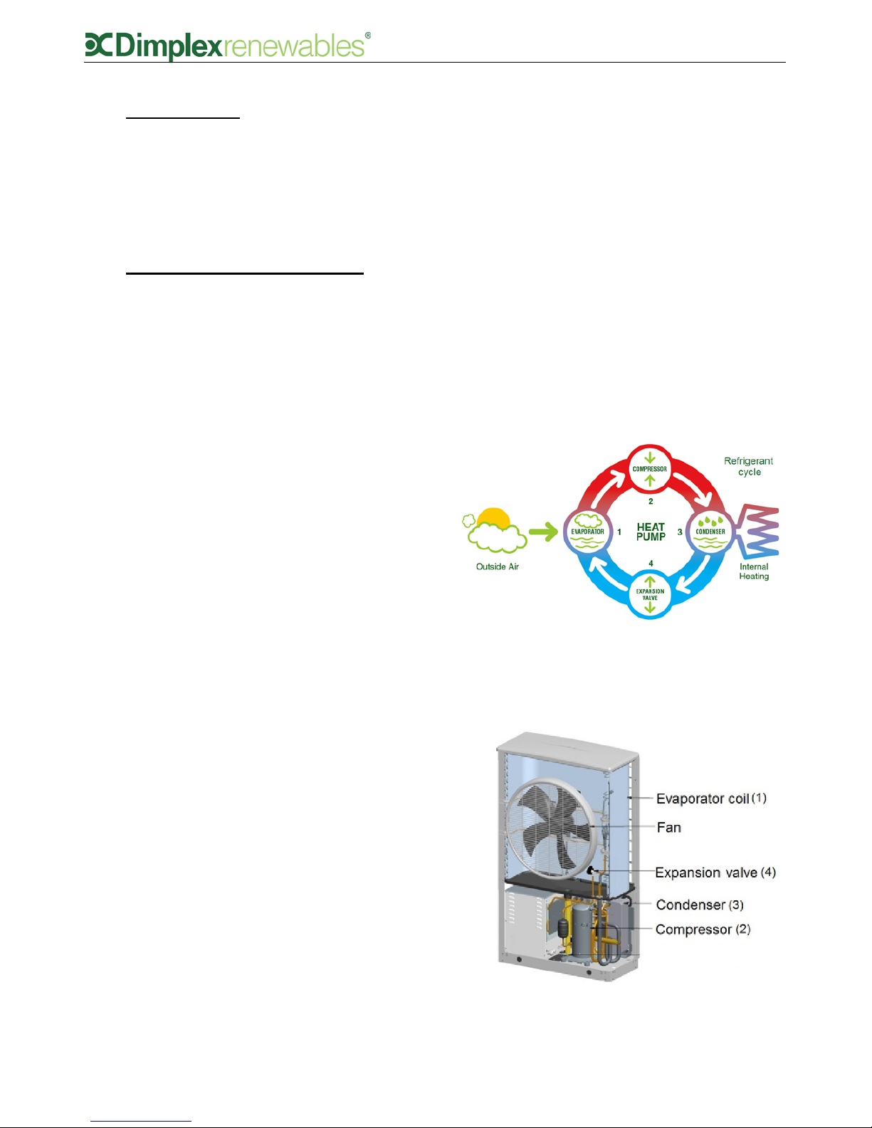
2 How the heat pump works
The operation of the heat pump is shown in
figure 1 below. A heat pump works on the same
principle as a fridge using a refrigerant fluid
which boils at a low temperature. Free energy is
take from the air to boil the refrigerant in the
evaporator coil (1), changing it from a liquid to
a vapour. This low grade heat is upgraded by
the compressor (2) increasing its pressure, and
consequently its temperature, to a useful high
temperature. The heat is transferred to your
heating system by the condenser (3), where the
refrigerant becomes liquid once again. The
liquid refrigerant is then expanded using an
expansion valve to a low pressure fluid before
repeating the cycle. 60-80% of the heat
generated by the heat pump comes from the
free energy taken from the air, compared to 2040% generated by the electricity used to power
the heat pump.
2.1 Tips and advice to follow when
using your new heat pump
• Glen Dimplex heat pumps are designed
with efficiency in mind. As a result of
using our renewable technology rather
than combustion or fossil fuels, the hot
water used to heat your home is heated
gradually, which allows the system to only
use as much energy as is required.
Because of this however, it will be
necessary to set your new heating system
to heat water/rooms a little while before
you would have had to set a traditional oil
or gas heating system, in order to allow
ample time for the desired temperatures
to be achieved.
• When using a Glen Dimplex heating
system, it is important to remember that
it is not possible to have the DHW and
space heating switched on at the same
time. If, for example, you require both hot
water and heating in the morning, it is
recommended to use the DHW function
first, followed by the space heating. The
insulation used on our cylinders ensures
that hot water will stay hot for as long as
possible, however it generally takes longer
to initially heat the DHW than for the
space heating to take effect.
When programming timer settings on the
UI, please check that the timer set for the
space heating and DHW do not overlap, as
the DHW function will automatically take
priority.
Figure 2: Inside the Heat Pump
Figure 1: Refrigeration Cycle
Page 4
2
3 Heating System Controller
(User Interface)
The controller/user interface that is supplied
with the Dimplex A-Class heat pump is used as
a heat pump controller as well as a heating and
domestic hot water (DHW) controller. It is also
the preferred option for use as a temperature
control device. The functions available for each
of these applications are explained in section 4.
When your heat pump system was installed, the
installer would have discussed with you the
different temperature control device options
available. While only one user interface is
currently available per system, there are
additional options of either temperature probes
or mechanical thermostats, which can be used
to control the temperature in up to four zones.
Mechanical thermostats provide less control
over the heating system, while the temperature
probe option allows the heat pump to sense
changes in demand and adjust accordingly. The
temperature probe option is generally
recommended over the mechanical thermostat
option.
A zone is defined as the physical area of your
home in which temperatures are controlled by
each individual device. For example, you might
have the user interface installed in your living
area, in which case this may be referred to as
zone 1. You may also install a temperature
probe upstairs in the sleeping/bedroom area,
which would then be designated as zone 2, and
so on. Extra zones are an additional, optional
feature of the heating system. The standard
package comes with one User Interface and the
possibility of four separate zones.
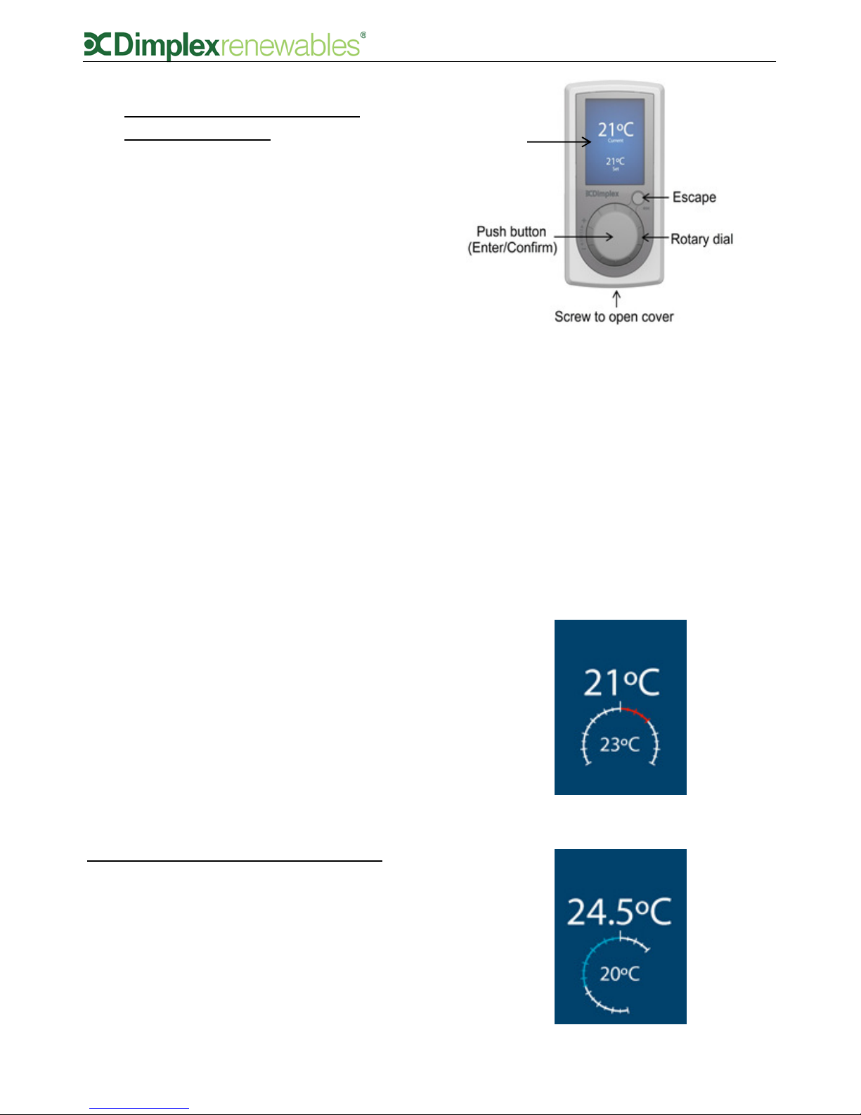
4 Operating the User Interface
• Select – click middle of dial (Enter/
Confirm)
• Change selected value – turn dial to
desired value
• Confirm change – click middle of dial
(Enter/Confirm)
• Back up one level – click small ’Esc’ button
(Escape)
4.1 Temperature
If the UI is not in use, the screen will switch to
screensaver mode after ten seconds, which
displays the current and set point temperature,
as shown in figure 3. When using a
mechanical thermosta t to cont rol
temperature in zone 1, the screensaver
feature will not be available. Turning the dial
left or right will decrease or increase the
temperature. Clicking the middle of the dial
confirms the new set point temperature for
zone 1.
Figure 3: Main User Interface (UI)
(Esc)
Temperature
Display
Screensaver
Figure 4(a): Increasing zone temperature
Figure 4(b): Decreasing zone temperature
Page 5

3
4.2 Home screen
The home screen, as shown in figure 5, is
accessed by pressing confirm from the
temperature screensaver.
Example - at 2.55 a.m. on Monday 22nd
November:
• Current water temperature in cylinder:
38°C
• Zone 1 temperature: 21°C
• Outside temperature: 5°C
• No temporary mode set
• No messages (‘i’ is white)
The home screen provides information on the
current system temperature, zone 1 and
outside temperatures, the temporary mode that
is selected (if any) and an alert if any messages
are present. From the home screen, you can
access the following menus:
Domestic hot water menu:
Set the heating mode of the hot water cylinder,
set time periods for the timer, boost the hot
water and set disinfection parameters. The
temperature that appears on the DHW icon on
the home screen is the current water
temperature.
Space heating menu:
Set the temperature of the space heating in
each zone, set heating to either ON, OFF or ON
TIMER mode, and set TIMER schedule settings.
Temporary mode menu:
Select from 3 different temporary modes: Going
Out, Home Early and Holiday mode. See section
4.6 for details.
Information screen:
View details on the heat pump, the current
operation of the various parts of the heating
system, the system run time history and any
warning messages that may occur.
4.3 Space Heating
Selecting the space heating icon from the home
screen will take you to the space heating menu,
shown in figure 6.
Figure 5: Home screen explained
Space Heating
Domestic
Hot Water
(DHW)
Temporary
Mode
Information
Figure 6: Space Heating menu explained
Operating Mode
Zone
Temperatures
& Comfort
Level
Timer
Setting
Page 6

4
Example:
• Room temperature is 21°C
• Heater is on
• TIMER mode selected
• Option 1 time period is selected
• At 9.35am the zone temperature will
decrease to 15°C (setback mode), as this
is the next change.
Zone temperatures:
This icon shows the zone 1 temperature. The
temperature of all zones can be controlled using
this menu, as shown in figure 7(a) and 7(b).
Operating mode:
This icon shows what mode the space heating is
running in: ON, OFF or TIMER. At initial start-up
the space heating setting is OFF and will need
to be adjusted to constantly ON or in TIMER
mode. Selecting the TIMER menu allows you to
select a predefined programme which can be
modified in the ‘Setting’ menu.
Setting:
Set up time periods for the space heating to
come on and off.
4.3.1 Comfort levels
If you feel that the desired room air
temperature in your home is not being reached,
it is possible to increase the comfort level
settings on your UI, which changes the water
input temperature for your heating system.
Glen Dimplex heat pumps allow for weather
compensation, and operate on a heating curve,
which will set the flow (water input)
temperature automatically depending on
outside conditions. The heating curves for each
zone in your home would have been set up by
the installer during the heat pump installation.
Changing the water input temperature will
change the response time for your heating
system.
In the comfort level submenu, as shown in
figure 8, it is possible to alter the water input
temperature for your system within a range of
6°C (-3°C to +3°C).
A warmer water input temperature will
increase energy consumption and
therefore running costs - every 1°C
reduction in the system’s water input
tem p e rat u re will re duc e en e rgy
consumption by 2.5%.
You can set your comfort level to automatically
remain set for anything from 1 hour to 14 days
(for short term changes or seasonal
adjustments), or if you wish to keep your
settings permanently, there is a permanent
setting option which will stay as set until you
change it again manually. The default comfort
level setting is 0.
Figure 7(a): Selecting a zone in the Zone
Temperatures submenu
Figure 7(b): Selecting a temperature for Zone 1
Figure 8: Adjusting comfort level
Page 7

5
4.3.2 Operating modes
Clicking on the clock icon allows you to select
from one of three running modes:
TIMER mode activates the pre-set timer
programmes.
ON mode turns the heating constantly on.
OFF mode turns the heating constantly off.
When the heating is set to OFF, you will be
asked for a setback temperature, as shown in
figure 9(b). This temperature is the OFF
temperature, which operates as a frost
protection feature. It is also the minimum room
temperature when the system is idle, and is
used as the set point temperature in between
programmed TIMER periods. It is set to a
default of 15°C but can be changed to suit the
climate.
4.3.3 Setting time periods
Time periods are pre-set but can be changed. 5
different ‘Options’ are available, each of which
can have up to 3 time period settings, and are
accessible by selecting the ‘Setting’ icon in the
space heating menu.
Figure 9(a): Selecting a zone in the Operating
Mode menu
Figure 9(c): Selecting operating mode, which
includes the option to change the day and time
period (Option 1)
Figure 9(b): Selecting a Setback temperature
Figure 10(a): Selecting a time period (Options 1-5)
Figure 10(b): Selecting time and temperature
settings for each option.
Page 8

6
Pre-set time periods
A number of time period have been pre-set to
typical heating time periods, to aid in quick and
easy initial set up. For example, Option 1 has
been set up as follows:
Period 1 21°C 06:00 – 09:00
Period 2 19°C 12:00 – 14:00
Period 3 21°C 17:00 – 22:00
The pre-set time periods can be easy changed to
suit your preference by selecting the Space
heating menu and the ‘Setting’ option.
Quiet Mode
Runs the heat pump in quiet mode, which may
be desirable at night if the heat pump is located
near bedrooms. Please note that in quiet mode it
will take longer to reach the set temperature as
the heat pump is running at a lower capacity in
order to reduce noise.
4.4 Domestic hot water (DHW)
Selecting the domestic hot water icon from the
home screen will take you to the domestic hot
water menu, shown in figure 11.
Water temperature:
This icon shows the set point temperature of the
DHW. You can also adjust the set point hot water
temperature here by turning the dial up or down
and then pressing it in to confirm, provided that
the TIMER mode is not set (TIMER mode
overrides all temperature changes except the
temporary modes explained in section 4.6 and
the Boost function).
A practical temperature for domestic hot water is
45°C. The A-Class cylinder and heat pump
together can typically achieve up to 60°C. The
maximum achievable temperature for the heat
pump is measured during commissioning, and an
indication is given when selecting the DHW setpoint if the immersion will be required to achieve
the set-point (adjusting the temperature of the
DHW above the maximum cylinder temperature
causes the immersion to be used to heat the
water above this maximum temperature).
Operating mode:
This icon shows what mode the domestic hot
water is running in: ON, OFF or TIMER. The
default setting is OFF, but can be adjusted to
constantly on or in TIMER mode by selecting the
mode icon and turning the dial. Selecting the
TIMER menu allows you to select a predefined
programme which can be modified in the ‘Setting’
menu.
Water
Temperature
(Set Point)
Setting
(Schedule Timer)
Disinfection
Settings
Figure 11: DHW screen explained
Operating Mode
Boost
Button
Figure 12: Setting a new temperature using the Water
Temperature function
Page 9

7
Figure 15: Setting disinfection frequency and time
Boost:
When using TIMER mode, you may want to use
DHW before the next scheduled period, for
example, if you arrive home from work early
and want to take a shower, but the DHW isn’t
scheduled to run until later. In this case, the
Boost function can be used to override the
TIMER until the water in the cylinder reaches
the set point temperature.
Disinfect:
Enable disinfection and set the time when it will
occur.
Setting:
Set up time periods for the hot water to come
on and off. Time periods (in the ‘Setting’ menu)
are pre-set but can be modified. There are
three types of settings you can store at one
time; Weekdays, Weekends and Custom time
periods, shown in figure 13(a). Up to 3 periods
can be chosen for each setting, as shown in
figure 13(b).
The time periods selected in ‘Setting’ can be
applied in TIMER mode, as shown in figure 14.
4.4.1 Disinfection
Disinfection is a function which keeps the level
of legionella bacteria in the cylinder under
acceptable levels. This is carried out by heating
the hot water in the cylinder to a high
temperature for a minimum set time. The
disinfection settings are pre-defined in the User
interface. If you wish you can change the
frequency of disinfection and the time that it
takes place, as shown in figure 10.
4.5 Information
Selecting the information icon from the home
screen will take you to the information menu.
The information menu provides you with details
of the settings which are currently active, as
shown in figure 16.
Figure 13(a): Setting menu options
Figure 14: Each setting from the ‘Setting’ menu
can be set on TIMER mode using the ‘Running
Mode’ menu
Figure 13(b): Three time periods are available
in the ‘Setting’ menu for each setting
Page 10

8
The icons will be highlighted in green if that
part of the system is on and white if it is off.
Some of the symbols displayed on this screen
will depend on the set up of your heating
system, therefore some icons may not be
visible. In this screen, you can also access an
additional menu which allows you to change the
date and time, the outside off temperature and
to view a list of any messages that occur. This
menu is accessed by turning the rotary dial to
the ‘Login’ button and middle clicking. Turn the
dial to ‘998’ and middle click again.
4.5.1 Adjusting the date and time
The date and time will be set during installation.
If for any reason you need to adjust these
settings you can do so by using the ‘Login’
button in the information screen, as shown in
figure 17. Turn the rotary dial to the login
button and middle click. Turn the dial to ‘998’
and middle click again.
4.5.2 Information – Message list
If the information symbol on the home screen is
highlighted orange, it means a minor fault has
occurred. When the message icon is highlighted
in red on the home screen, it usually means
there is an issue with the operation of the heat
pump. When you see this you must contact the
heat pump installer and provide them with the
error code.
The full message list can be viewed by entering
998, similar to the date and time menu
described in section 4.5.1. If a message is
active, it will be highlighted orange. Selecting
the message (by middle clicking the rotary dial)
will open a list of details about the system
operation the moment the message occurred.
4.5.3 Changing outside off temperature
You may not require your heat pump to come
on in warmer months, when the outside air
temperature reaches a certain level. You can
change the outside off temperature in the
information menu, by entering ‘Login = 998’ as
before. In this menu you will see a submenu
called ‘General DHW & Heating Control’.
Accessing this menu will allow you to change
the outside off temperature, by clicking on the
temperature and turning the dial to increase or
decrease the temperature.
If the outside off temperature is set too low for
your environment (e.g. default outside off
temperature is 18°C) and the temperature
outside surpasses this (e.g. it is 20°C outside
during summer), the heating will be switched
off and will revert back to the set back
temperature (see section 4.3.3) until the next
change. This can be prevented by increasing
the outside off temperature.
You will also find a number of other sub menus
in the ‘Login = 998’ menu. These menus display
information about temperatures in each zone,
which may be required when speaking to a
service agent.
Backup Heater
Space Heating
Heat Pump
Cylinder Immersion
Bivalent Boiler
Domestic Hot Water (DHW)
Login
Figure 16: Information Screen explained
Page 11

9
4.6 Temporary modes
A number of temporary modes can be set which
override the running mode settings, as shown in
figure 17. This can be used, for example, if you
have set up your heat pump so that it comes on
during set hours on weekdays and different set
hours during weekends, but would like to turn
your heating on at a different time than usual
without affecting your day to day settings.
NOTE: If you have your heat pump set up to
run in TIMER mode, changing the temperature
for the primary zone using the screen saver
mode will NOT work. Once the heat pump is
running in TIMER mode, a temporary mode or
the Boost function must be used if you want to
override the timer without changing your TIMER
settings/time periods.
4.6.1 Going Out
This mode turns OFF space heating until the
next scheduled ON time, when in TIMER mode.
4.6.2 Home Early
This mode turns ON your space heating until
the next scheduled OFF time, when in TIMER
mode.
4.6.3 Holiday mode
This mode allows you to set the space heating
and DHW in OFF mode while on holidays. By
setting the start date and number of days you
will be on holidays for, the heat pump saves
your return date, and turns the heating on 2
days before your return if you have under-floor
heating and 1 day before if you have Smartrads
or radiators., after which the schedule will
return to its previous settings. It will also run
disinfection 1 day before you return (at the set
disinfection time).
Figure 17: Temporary Modes menu
Figure 18: Going Out mode set. The heating will now
remain switched off until the next scheduled on time
Figure 19: Home Early mode set. The heating will
now remain turned on until the next scheduled OFF
time.
Figure 21: Holiday Mode screen
Page 12

10
5 Safety
• Installation and any service work on the
heat pump may only be performed by
authorised and qualified installer and after
-sales service technicians.
• This device is not suitable for operation
with an electrical generator and any
attempt to do so will void warranty.
• If the heat pump may be disconnected
from power supply for prolonged periods
of time or where power supplies are
susceptible to failure, antifreeze must be
added to the system.
• Additional heating may be required if heat
pump is intended to dry out a new or
renovated building, as the initial heat load
will be higher than the calculated load.
• Products not installed with the Dimplex
hydraulics packs will not be supported by
Dimplex. This includes but is not limited to
thermal stores.
• This appliance can be used by children
aged from 8 years and persons with
reduced physical, sensory or mental
capabilities, or lack of experience and
knowledge, provided that they have been
given supervi si o n or instruction
concerning use of the appliance in a safe
way and understand the hazards involved.
Children must not play with the appliance.
Cleaning and user maintenance must not
be carried out by children without
supervision.
6 Defrost
During colder weather, frost builds up on the
evaporator coil inside the heat pump. If this
frost remains in the evaporator, it will cause
blockages and will prevent air from flowing
efficiently through the heat pump, which will
result in poor performance. Therefore, when
frost starts to form on the evaporator coil, the
heat pump runs a defrost cycle. This lasts for
approximately 4 minutes and melts any frost
that is present.
Approximately 2 litres of condensate water is
drained from the system every time a defrost
cycle occurs. Therefore, it is essential that this
water is drained correctly. The heat pump is
supplied with a condensate pipe which must be
fed into a drain or soak away to allow for safe
disposal of the excess water. This will prevent
icy patches forming on footpaths or patios in
colder weather
7 Maintenance
Please see section 9 of the Installation manual
for ‘System Health Checks / Maintenance’
advice.
Page 13

11
 Loading...