

Page 1
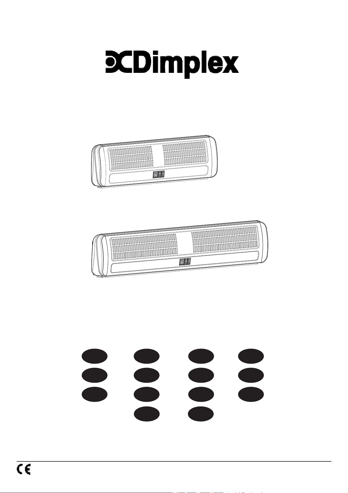
AC3N, AC3RN, AC45N, AC6N & AC6RN Air Curtains
AC3N, AC45N & AC3RN
PT
AC6N & AC6RN
DE
NL
SLPL NO SE
DK
FRUK
IT
FI
ES
RU
08/19062/0 - Issue 7
Products comply with the European Safety Standard: EN 60335-2-30 and the European Standards for Electromagetic Compatibility (EMC)
EN55014-1 / A2: 2002 and EN55014-2:2003. These cover the essential requirements of EEC directives 2006/95/EC and 2004/108/EC
Page 2
'C'
(a)
4
'B'
214
50
45
200
'A' 135
Model(s) Watt
AC3N 3.0kW
AC45N 4.5kW
AC6N 6.0kW
1
2
AC3RN 3.0kW
AC6RN 6.0kW
3
A
605
605
905
605
905
B
424
424
721
424
721
C
492
492
756
492
756
4
e
155
c
b
a
d
f
5
6
7a
8
O I
'A'
'B'
7b
'A'
'B'
Page 3
9
)
10
AUTO
I
11 12
AC3N, AC45N &AC6N
MAN
AC3RN
13
14
Page 4

UK ...................................................... 1
DE ...................................................... 2
FR ...................................................... 3
ES ...................................................... 4
PT ...................................................... 5
NL ...................................................... 6
IT ...................................................... 7
RU ...................................................... 8
PL ...................................................... 9
SL ...................................................... 10
NO ...................................................... 11
SE ...................................................... 12
DK ...................................................... 13
FI ...................................................... 14
Page 5
AC Air Curtains
- 1 -
UK
Models : AC3N, AC45N, AC6N, AC3RN & AC6RN
IMPORTANT: THESE INSTRUCTIONS SHOULD BE READ CAREFULLY
AND RETAINED FOR FUTURE REFERENCE
IMPORTANT SAFETY ADVICE
DO NOT COVER OR OBSTRUCT the air inlet or outlet grille.
ENSURE THE APPLIANCE IS EARTHED.
Do not use this heater in areas where excessive dust exists.
This heater must not be located immediately above or below a fi xed socket outlet or connection
box.
Always disconnect supply before working on the product.
This product should be mounted safely to solid wall or ceiling surfaces only.
Ensure the supply cables are of adequate current carrying capacity and are protected by a suitable
fuse.
If the appliance is mounted in a toilet or washroom, the appliance should be mounted such that no
part of it can be touched by a person using a fi xed bath or shower.
If the appliance is mounted in a toilet or washroom an isolating switch must be provided outside the
washroom adjacent to the entrance door.
This appliance can be used by children aged from 8 years and above and persons with reduced
physical, sensory or mental capabilities or lack of experience and knowledge if they have been given
supervision or instruction concerning use of the appliance in a safe way and understand the hazards
involved. Children shall not play with the appliance. Cleaning and user maintenance shall not be made
by children without supervision.
Children of less than 3 years should be kept away unless continuously supervised. Children aged
from 3 years and less than 8 years shall only switch on/off the appliance provided that it has been
placed or installed in its intended normal operating position and they have been given supervision
or instruction concerning use of the appliance in a safe way and understand the hazards involved.
Children aged from 3 years and less than 8 years shall not plug in, regulate and clean the appliance
or perform user maintenance.
CAUTION — Some parts of this product can become very hot and cause burns. Particular
attention has to be given where children and vulnerable people are present.
This heater is not equipped with a device to control the room temperature. Do not use this heater in
small rooms when they are occupied by persons not capable of leaving the room on their own, unless
constant supervision is provided.
Warning : In order to avoid a hazard due to inadvertent resetting of the thermal cut-out, this appliance
MUST NOT be supplied through an external switching device, such as a timer, or connected to a
circuit that is regularly switched on and off by the utility.
ATTENTION: IN ORDER TO
AVOID OVERHEATING DO
NOT COVER.
Electrical
The installation of this appliance should be carried out by a
competent electrician and be in accordance with the current IEE
wiring regulations.
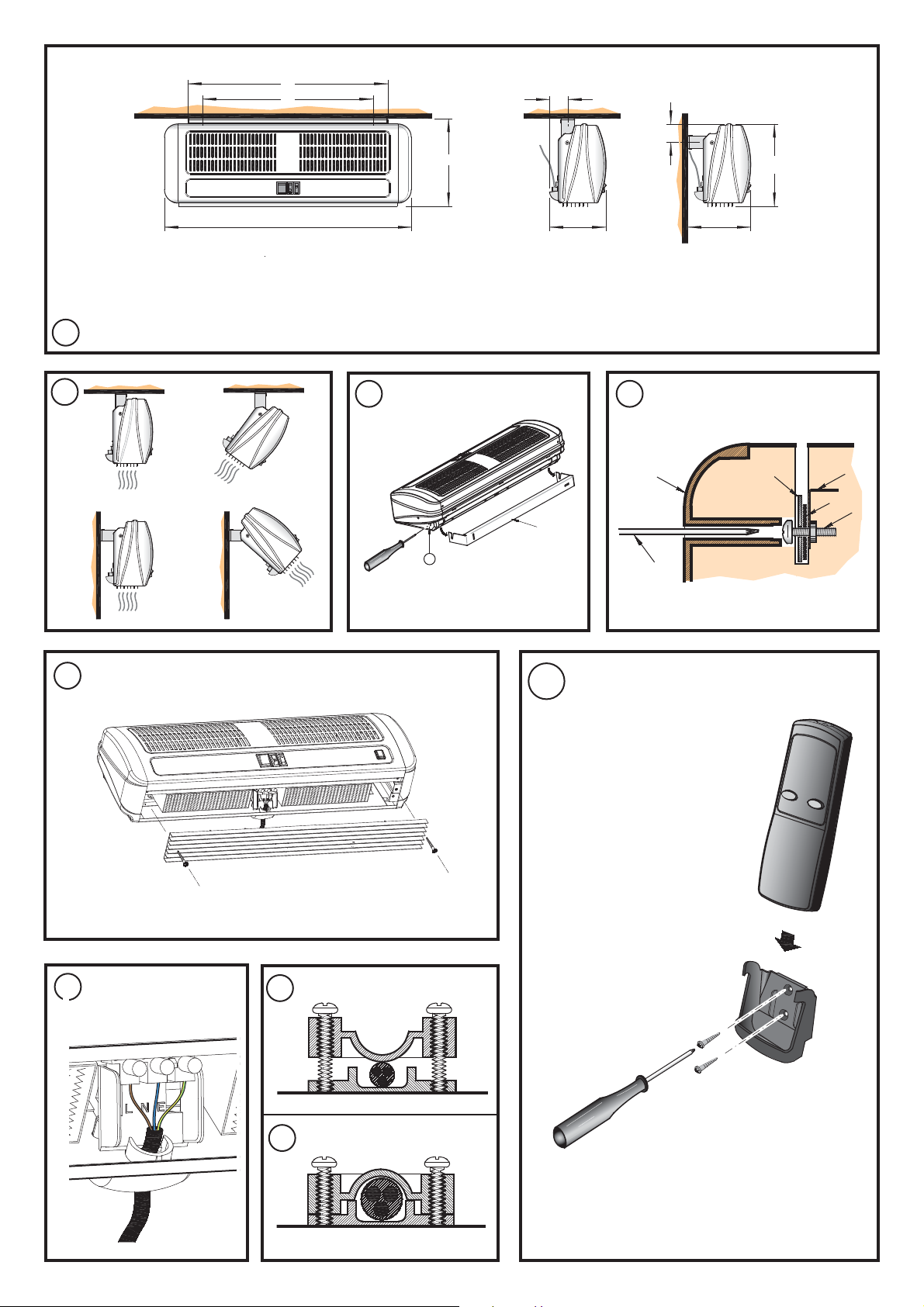
Fixing Positions
This appliance may be either wall-mounted or fi xed to a ceiling -
see Fig. 2 for various fi xing positions and ‘Installation’ see section
below, for details on fi xing. Heaters may be mounted end to end
for wide doorways.
Installation
Using the wall mounting bracket as a guide (see ‘a’ in Fig. 3) mark
off the hole positions on the wall or ceiling (see ‘B’ in Fig. 1). A
minimum height of 1.8 metres is required from fl oor to bracket.
Fix the bracket in position by following steps as described under
the heading ‘Wall or Ceiling Mounting’.
Wall or Ceiling Mounting
Solid brick or concrete block walls must be drilled and plugged
(using a spirit level as a guide ensure bracket is level), due to
different types of wall constructions fi xings are not included, ensure
the correct fi xings are used. The plug must be located in the solid
part of the wall, not just in the plaster layer.
For panelled internal walls or ceilings, it is best to locate the
studding, position the heater fi xing bracket accordingly and use
screws supplied. If it is not possible to locate the studding, use
type M5 Rawlplug inserts, making the 10mm holes with a drill
rather than a bradawl or a screwdriver.
Locate the heater on the mounting bracket ensuring that the pozihead screws are fully engaged in the slots of the bracket.
It is important that the serrated metal washer (a) is located between
the heater holding bracket (b) and the wall mounting bracket (c).
Page 6
Adjust heater to the required angle then fi rmly tighten the fi xing
screw (d) inside the endcap (e) using a cross-head screwdriver
(f) as shown in Fig. 4.
Electrical connection
Release the screws at either end of the air-outlet grille (see Fig.
5) to gain access to the terminals for connection of the supply
cable - see Fig. 6.
Insert the mains cable down the outside of the back panel (not
on inside) and through the rear entry cable clamp and make
connection as shown in Fig. 6 (see also Fig. 7 for detailed views
of cable clamp).
Fig. 7a shows the cable clamp detail for AC3N & AC3RN
models.
Fig. 7b shows cable clamp detail for AC45N & AC6N models.
Note : Part ‘A’ of cable clamp is fl ipped over to receive the larger
cable.
Connection to fi xed wiring should be made through an adjacent
minimum 20 amp double-pole switch for AC3N, AC3RN & AC45N
models.
Connection to fi xed wiring should be made through an adjacent
minimum 30 amp double-pole switch for AC6N model with a
minimum separation of 3mm in each pole.
Re-secure the outlet grille.
Ensure that the air-curtain is securely fastened and that the supply
cable is fi rmly clamped before operating the appliance.
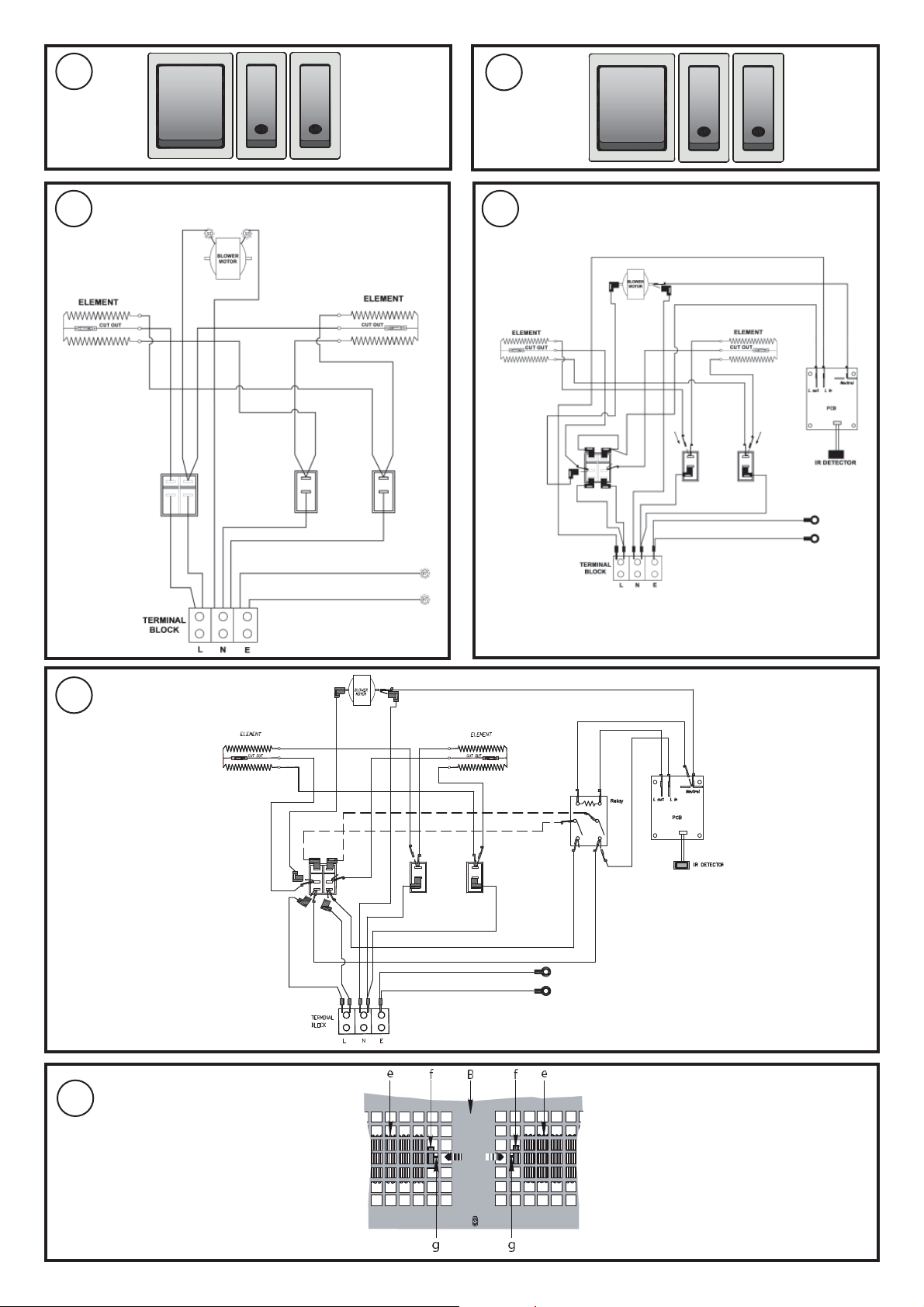
Operation (AC3N, AC45N & AC6N models)
Switch on electricity supply to the heater.
Switching the switch marked ‘I’ energises the blower.
Select ‘l’ and the smaller switches marked ‘’ as required (see
Fig. 9)
Settings - I : Fan ‘On’
I + : Half heat
I + + : Full heat
Operation (AC3RN & AC6RN model)
Switch on electricity supply to the heater.
Select the switch position ‘MAN’ for Manual Operation.
Select the switch position ‘AUTO’ for Operation via the remote
control.
Select the desired heat output using the smaller switches marked
‘’ (see Fig. 10).
To operate the remote control you must first select
‘AUTO’. The heater may now be turned On or Off
using the Remote Control (see Fig. 8).
Settings - MAN : Fan On
AUTO : Fan On or Off (using remote I / O)
MAN / AUTO + : Half heat
MAN / AUTO + + : Full heat
AUTO
’ will default to ‘OFF’ if the remote control is not being
‘
used.
NOTE. Infra red technology is used for the remote control link, the
range is 8 meters in line of slight.
If the remote control becomes lost, switch off at the mains supply
for at least 30 seconds and select ‘MAN’ for Manual Operation.
Remote Control (AC3RN & AC6RN model only)
Insert 2 off 1.5 volt AAA batteries into the remote control
handset.
Switch the heater to ‘AUTO’ for automatic operation.
Press the I button to activate the heater, and O to turn off.
If the remote control does not operate the heater, fi rst check
batteries, then point remote directly at the heater before
operating.
The remote control may be placed, when not in use, in the provided
wall-mounted holster (see Fig. 8). Screws and rawlplugs for wall
fi xing the holster are provided.
Important Battery Information
Discard leaking batteries.
Dispose of batteries in the proper manner according to Provincial
and local regulations. Any battery may leak electrolyte if mixed with
a different battery type, if inserted incorrectly, if all the batteries are
not replaced at the same time, if disposed of in a fi re or if an attempt
is made to charge a battery not intended to be recharged.
Thermal Safety Cut-outs
The power supply to the heating elements will be interrupted if one
or a combination of the following abnormal events occurs.
1. Air inlet or outlet grilles are obstructed.
2. Internal ventilation is impaired due to build up of dust and
fl uff.
3. Blower unit stalls.
Note : If the cut-out operates, the fan may continue to run
impairing the performance of the heater. If this occurs, turn off unit
immediately and follow the reset procedure below.
Procedure for resetting cut-out(s)
Establish cause and eliminate.
Follow the steps below to reset cut-out(s)
1. Disconnect power supply.
2. Pass small fl at head screwdriver through Air Inlet/Outlet
panel ‘B’ to button side of cut-out (see ‘g’ in Fig. 14) avoiding
contact with element (see ‘e’ in Fig. 14).
3. Press reset button in direction shown in Fig. 14 to reset cutout. (Cut-out clicks when reset)
4. Remove screwdriver carefully.
5. Turn on supply.
If the cut-out continues to operate intermittently, the heater
should be switched off and a service agent contacted.
Maintenance
WARNING : Disconnect the heater from the mains
supply before carrying out maintenance.
This product is designed to require no maintenance. If operated
in an extremely dusty environment it may however be necessary
to carefully brush clean the air-inlet grille from time to time.
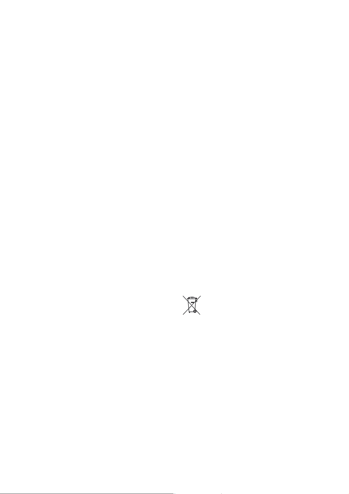
Recycling
For electrical products sold within the European Community.
At the end of the electrical products useful life it should
not be disposed of with household waste. Please recycle
where facilities exist. Check with your Local Authority or
retailer for recycling advice in your country.
Cleaning
WARNING: ALWAYS DISCONNECT POWER
SUPPLY before cleaning the heater.
Do not use detergents, abrasive cleaning powders or polish of
any kind on the heater.
External appearance can be maintained by wiping occasionally
with a damp cloth ; for stain removal, a weak soap solution can
be applied with a cloth and the surface wiped dry. Care must be
taken to avoid any moisture ingress into the product.
Ensure that dust or fl uff does not accumulate inside the heater
as this could lead to overheating of the element. Use a vacuum
cleaner to remove any fl uff which does accumulate.
After Sales Service
Should you require after sales service or should you need to
purchase any spares, please contact the retailer from whom the
appliance was purchased or contact the service number relevant
to your country on the warranty card.
Please do not return a faulty product to us in the fi rst instance as
this may result in loss or damage and delay in providing you with
a satisfactory service.
Please retain your receipt as proof of purchase.
Page 7

AC Luftschleier
- 2 -
Modelle: AC3N, AC45N, AC6N, AC3RN und AC6RN
WICHTIG: DIESE ANWEISUNGEN SORGFÄLTIG LESEN UND FÜR SPÄTERE REFERENZ AUFBEWAHREN
DE
WICHTIGE SICHERHEITSHINWEISE
Den Lufteinlass oder Luftauslass NICHT ABDECKEN ODER BLOCKIEREN.
SICHERSTELLEN, DASS DAS HEIZGERÄT GEERDET IST.
Dieses Heizgerät nicht in Bereichen betreiben, in denen es verstärkt Staub ausgesetzt ist.
Dieses Heizgerät darf nicht direkt über oder unter einer festen Steckdose oder Abzweigdose
montiert werden.
Vor dem Ausführen von Arbeiten am Produkt stets die Stromversorgung trennen.
Die Geräte muss sicher an stabilen Wand- oder Deckenfl ächen befestigt werden.
Sicherstellen, dass alle elektrischen Leitungen eine entsprechende Strombelastbarkeit
aufweisen und mit einer geeigneten Sicherung geschützt sind.
Wenn das Heizgerät in einer Toilette oder einem Badezimmer montiert wird, dann muss es so
montiert werden, dass kein Teil von einer Person in einer Badewanne oder Dusche berührt
werden kann.
Wenn die Einheit in einer Toilette oder einem Badezimmer montiert wird, dann muss sich
außerhalb des Badezimmers ein Trennschutzschalter neben der Eingangstür befi nden.
Warnung: Um Gefahr durch ungewünschtes Zurücksetzen des Überhitzungsschutzes zu
vermeiden, darf diese Einheit nicht durch ein externes Schaltgerät (z. B. einen Zeitschalter) mit
Strom versorgt oder an einen Schaltkreis angeschlossen werden, der vom Versorgungsbetrieb
regelmäßig ein- und ausgeschaltet wird.
Elektrik
Diese Einheit sollte von einem ausgebildeten Elektriker in Übereinstimmung mit den aktuellen
Verdrahtungsvorschriften der IEE montiert werden.
Befestigung
Die Einheit kann entweder an der Wand oder der Decke befestigt werden. Siehe Abbildung 2 mit
verschiedenen Befestigungen und den Abschnitt „Montageort“ unten mit Befestigungsdetails. Bei breiten
Türöffnungen können Heizgeräte längs hintereinander montiert werden.
Montageort
Mit Hilfe der Wandhalterung (siehe „a“ in Abbildung 3) die Position der Bohrungen an der Wand oder
der Decke markieren (siehe „B“ in Abbildung 1). Es wird eine Mindesthöhe von 1,8 m zwischen dem
Fußboden und der Wandhalterung benötigt. Die Wandhalterung mit den unter „Wand- oder Deckenmontage“
beschriebenen Schritten befestigen.
Wand- oder Deckenmontage
Bohrungen in stabilem Mauerwerk oder Zementwänden müssen mit den im Lieferumfang enthaltenen
Spreizdübel-Fasereinsätzen gebohrt und gedübelt werden. (Dabei eine Richtwaage zur Ausrichtung der
Halterung verwenden.) Der Dübel muss sich im stabilen Wandteil befi nden - nicht nur im Verputz.
Bei getäfelten Innenwänden oder -decken zuerst die Beschläge suchen und dann die Befestigungshalterung
des Heizgeräts mit den im Lieferumfang enthaltenen Schrauben entsprechend anbringen. Wenn die
Beschläge nicht gefunden werden können, Spreizdübel-Einsätze Typ M5 verwenden. Die 10 mm großen
Bohrungen mit einem Bohrer vornehmen, nicht mit einer Ahle oder einem Schraubendreher.
Das Heizgerät in der Montagehalterung anbringen und sicherstellen, dass die Pozidriv-Schrauben vollständig
in die Schlitze der Halterung eingehängt sind.
Es ist wichtig, dass sich die Fächer-Unterlegscheibe aus Metall (a) zwischen der Montagehalterung des
Heizgeräts (b) und der Wandhalterung (c) befi ndet. Das Heizgerät im gewünschten Winkel einstellen, dann
die Schraube (d) im Inneren der Kappe (e) mit einem Kreuzschlitzschraubendreher (f) festziehen - siehe
Abbildung 4.
Anschluss der Stromversorgung
Die Schrauben an beiden Enden des Luftauslasses entfernen (siehe Abbildung 5), um Zugang zu den
Kabelanschlüssen für das Stromkabel zu erhalten - siehe Abbildung 6.
Das Stromkabel an der Außenseite der Rückwand (nicht an der Innenseite) entlang und durch den hinteren
Kabeleingang verlegen und das Kabel wie in Abbildung 6 gezeigt anschließen (siehe Abbildung 7 für
eine detaillierte Ansicht des Kabeleingangs).
Abbildung 7a zeigt den Kabeleingang für Modelle AC3N und AC3RN.
Abbildung 7b zeigt den Kabeleingang für Modelle AC45N und AC6N. Hinweis: Teil „A“ des Kabeleingangs
wird bei Verwendung des größeren Kabels umgedreht.
Der Anschluss an festverlegte Leitungen sollte für die Modelle AC3N, AC3RN und AC45N über einen
benachbarten doppelpoligen 20-Ampere-Schalter erfolgen.
Der Anschluss an festverlegte Leitungen sollte für das Modell AC6N über einen benachbarten doppelpoligen
30-Ampere-Schalter mit einem Abstand von mindestens 3 mm in jedem Pol erfolgen.
Den Luftauslass wieder anbringen.
Vor Betrieb der Einheit sicherstellen, dass der Luftschleier sicher befestigt ist und dass die Stromkabel
fest eingespannt sind.
Betrieb (Modelle AC3N, AC45N und AC6N)
Die Stromversorgung zum Heizgerät einschalten.
Der mit „I“ gekennzeichnete Schalter schaltet den Lüfter ein.
„l“ und die kleineren, mit „“ markierten Schalter je nach Bedarf auswählen (siehe Abbildung 9)
Einstellungen - I : Lüfter „Ein“
I + : Halbe Wärme
I + + : Volle Wärme
Fernbedienung (Nur Modell AC3RN und AC6RN)
Zwei 1,5 Volt AAA-Batterien in die Fernbedienung einlegen.
Das Heizgerät auf „AUTO“ für automatischen Betrieb stellen.
I drücken, um das Heizgerät zu aktivieren. Mit der Taste O abschalten.
Taste
Wenn das Heizgerät nicht mit der Fernbedienung bedient werden kann, zunächst die Batterien prüfen, und
die Fernbedienung direkt auf das Heizgerät richten.
Die Fernbedienung kann in der im Lieferumfang enthaltenen Wandhalterung aufbewahrt werden, wenn sie
nicht verwendet wird (siehe Abbildung 8). Schrauben und Dübel zur Montage der Wandhalterung für die
Fernbedienung sind im Lieferumfang enthalten.
Wichtige Informationen zu Batterien
Auslaufende Batterien entsorgen.
Die Batterien in Übereinstimmung mit regionalen und lokalen Vorschriften entsorgen. Jede Batterie kann
lecken, wenn sie mit einem anderen Batterietyp verwendet oder falsch eingesetzt wurde, wenn Batterien
nicht gleichzeitig ausgetauscht werden, in einem Feuer entsorgt werden oder wenn eine nicht aufl adbare
Batterie aufgeladen wird.
Überhitzungsschutz
Die Stromversorgung der Heizelemente wird unterbrochen, wenn einer der folgenden oder eine Kombination
der folgenden ungewöhnlichen Vorfälle auftreten.
1. Lufteinlass oder Luftauslass sind blockiert.
2. Die interne Luftzirkulation ist durch Ansammlung von Staub und Fusseln beeinträchtigt.
3. Die Lüftereinheit blockiert.
Hinweis: Wenn der Überhitzungsschutz aktiviert wird, läuft das Gebläse ggf. weiter, wodurch die Leistung
des Heizgeräts vermindert wird. In diesem Fall die Einheit sofort ausschalten und den unten beschriebenen
Zurücksetzvorgang durchführen.
Zurücksetzen des Überhitzungsschutzes
1. Das Gerät von der Stromversorgung trennen.
2. Die Ursache der Sicherheitsabschaltung ermitteln und beseitigen.
(Hinweis: Dies sollte nur von fachkundigen Personen mit Erfahrung beim Reparieren von elektrischen
Geräten und unter Berücksichtigung der möglichen Gefahren durchgeführt werden).
3. Nach kurzer Zeit (nachdem sich das Heizgerät abgekühlt hat) erlaubt der Überhitzungsschutz die
Verbindung zum Stromnetz wieder; das Heizgerät nimmt den normalen Betrieb wieder auf.
Wartung
WARNUNG: Vor Wartungsarbeiten das Heizgerät vom Stromnetz trennen.
Dieses Produkt wurde so entwickelt, dass keine Wartungsarbeiten vonnöten sind. Wenn das Gerät in einer
sehr staubigen Umgebung betrieben wird, ist es u. U. nötig, den Luftauslass von Zeit zu Zeit vorsichtig
abzubürsten.
Recycling
Für Elektrogeräte, die in der Europäischen Gemeinschaft verkauft wurden.
Kaputte Elektrogeräte dürfen nicht im Hausmüll entsorgt werden. Wenn möglich sollten sie
recycelt werden. Informationen zu Recycling in Ihrem Land erhalten Sie von den örtlichen
Behörden oder von Ihrem Händler.
Reinigung
WARNUNG: Vor dem Reinigen des Heizgeräts IMMER ZUNÄCHST DIE STROMVERSORGUNG
UNTERBRECHEN.
Keine Lösungsmittel, Scheuerpulver oder Politur auf dem Heizgerät verwenden.
Die Außenfl ächen können durch gelegentliches Abwischen mit einem feuchten Tuch gereinigt werden. Um
Verschmutzungen zu reinigen, kann eine milde Seifenlösung mit einem Tuch aufgetragen und die Oberfl äche
abgetrocknet werden. Das Eindringen von Feuchtigkeit in das Produkt muss vermieden werden.
Sicherstellen, dass sich im Inneren des Heizgeräts kein Staub oder keine Fussel ansammeln, da dies zur
Überhitzung des Heizelements führen kann. Angesammelte Fussel mit einem Staubsauger entfernen.
Kundendienst
Wenn Sie den Kundendienst benötigen oder Ersatzteile bestellen möchten, bitte den Händler kontaktieren,
von dem das Gerät erworben wurde, oder die für Ihr Land zutreffende Kundendienst-Telefonnummer auf
dem Garantieschein anrufen.
Ein fehlerhaftes Produkt bitte zunächst nicht an uns zurücksenden, da dies Verlust oder Beschädigungen
des Produkts zur Folge haben sowie die Bereitstellung einer angemessenen Kundendienstleistung
verzögern könnte.
Bitte bewahren Sie Ihre Quittung als Kaufnachweis auf.
Betrieb (Modell AC3RN und AC6RN)
Die Stromversorgung zum Heizgerät einschalten.
Zum manuellen Betrieb den Schalter auf „MAN“ stellen.
Zum Betrieb über die Fernbedienung den Schalter auf die Position „AUTO“ stellen.
Die gewünschte Wärmeeinstellung über die kleineren, mit „ “ markierten Schalter auswählen
(siehe Abbildung 10).
Zum Betrieb über die Fernbedienung muss zuerst „AUTO“ ausgewählt werden. Das Heizgerät kann
nun über die Fernbedienung ein- und ausgeschaltet werden (siehe Abbildung 8).
Einstellungen - MAN : Lüfter Ein
AUTO : Lüfter Ein oder Aus
(I / O auf Fernbedienung)
MAN / AUTO + : Halbe Wärme
MAN / AUTO + + : Volle Wärme
AUTO
“ stellt automatisch auf „AUS“, wenn die Fernbedienung nicht verwendet wird.
„
HINWEIS: Die Fernbedienung verwendet Infrarot-Technologie. Die Reichweite beträgt 8 m in Sichtlinie.
Wenn die Fernbedienung verloren geht, die Stromversorgung mindestens 30 Sekunden lang trennen und
„MAN“ zum manuellen Betrieb auswählen.
Page 8

Rideaux d’air AC
- 3 -
Modèles : AC3N, AC45N, AC6N, AC3RN et AC6RN
IMPORTANT : LIRE ATTENTIVEMENT CES INSTRUCTIONS ET LES CONSERVER SOIGNEUSEMENT POUR POUVOIR LES CONSULTER ULTÉRIEUREMENT.
FR
CONSIGNES DE SÉCURITÉ IMPORTANTES
NE PAS COUVRIR NI OBSTRUER la grille d’entrée ou de sortie d’air.
S’ASSURER QUE L’APPAREIL EST RELIÉ À LA MASSE.
Ne pas utiliser cet appareil de chauffage dans des endroits très poussiéreux.
Cet appareil de chauffage ne doit pas être placé juste au-dessus ou en dessous d’une prise ou
d’un boîtier de connexion fi xes.
Toujours débrancher l’alimentation avant d’effectuer toute opération d’entretien sur ce
produit.
Ce produit doit être monté en toute sécurité sur un mur ou un plafond solides uniquement.
S’assurer que les câbles d’alimentation ont une intensité de courant admissible correcte et
qu’ils sont protégés par un fusible adapté.
Dans des toilettes ou salles d’eau, le dispositif doit être monté de telle sorte qu’aucune pièce ne
puisse être accessible par une personne utilisant une baignoire ou une douche fi xées au sol.
Dans les toilettes ou salles d’eau, un sectionneur doit être installé à l’extérieur de la pièce, à
côté de la porte d’entrée.
Avertissement : Pour éviter les risques liés à la réinitialisation accidentelle du disjoncteur, cet
appareil NE DOIT PAS être alimenté par un dispositif de connexion externe, tel qu’une minuterie,
ou branché à un circuit régulièrement mis hors et sous tension.
Installation électrique
L’installation de cet appareil doit être effectuée par un électricien compétent, conformément aux régulations
IEE en vigueur concernant les câblages électriques.
Positions de fi xation
Cet appareil peut être monté à un mur ou fi xé à un plafond ; pour connaître les différentes positions de fi xation
et obtenir des instructions de fi xation détaillées, voir la fi gure 2 et la section « Installation » ci-dessous. Pour
les portes plus larges, il est possible de monter plusieurs appareils de chauffage côte à côte.
Installation
En se basant sur le support de montage mural (voir l’élément « a » à la fi gure 3), marquer les emplacements
des orifi ces sur le mur ou au plafond (voir l’élément « B » à la fi gure 1). Veiller à ce que la hauteur entre
le sol et le support soit de 1,8 m minimum. Fixer le support en position conformément aux instructions de
la section « Montage mural ou au plafond ».
Montage mural ou au plafond
Pour ce qui est des murs en brique ou en parpains, effectuer des trous à la perceuse et les boucher à l’aide
des chevilles fournies (se munir d’un niveau pour s’assurer le positionnement correct du support). Les mèches
doivent être enfoncées dans la partie solide du mur et pas simplement dans la couche de plâtre.
Dans le cas de murs ou de plafonds cloisonnés, déterminer l’emplacement des chevilles, positionner le
support de fi xation de l’appareil de chauffage et fi xer à l’aide des vis fournies. Si les chevilles sont impossibles
à insérer, utiliser des chevilles de type M5 et, à l’aide d’une perceuse plutôt que d’un tournevis ou d’un
foret, effectuer des trous de 10 mm.
Positionner l’appareil de chauffage sur le support de montage en veillant à ce que les vis cruciformes
renforcées soit entièrement insérées dans les fentes du support.
Veiller à ce que la rondelle métallique sertie (a) soit située entre le support de fi xation de l’appareil de
chauffage (b) et le support de montage mural (c). Positionner l’appareil de chauffage à l’angle souhaité et
serrer fermement la vis de fi xation (d) située à l’intérieur de l’embout (e) à l’aide du tournevis cruciforme
(f), comme illustré à la fi gure 4.
Branchements
Retirer les vis de chaque côté de la grille de sortie d’air (voir fi gure 5) pour accéder aux terminaux et
connecter le câble d’alimentation (voir fi gure 6).
Insérer le câble électrique au bas et à l’extérieur du panneau arrière (et non à l’intérieur) en le faisant
passer à travers le collier de câble d’entrée arrière et en le connectant comme illustré à la fi gure 6 (voir
aussi la fi gure 7 pour une vue détaillée du collier de câble).
Le collier de serrage des modèles AC3N et AC3RN est illustré à la fi gure 7a.
Le collier de serrage des modèles AC45N et AC6N est illustré à la fi gure 7b. Remarque : Pour les câbles
plus larges, rabattre la partie « A » du collier de serrage.
Pour les modèles AC3N, AC3RN et AC45N, le branchement à un fi l fi xe doit se faire à l’aide d’un interrupteur
bipolaire adjacent de 20 A minimum.
Pour le modèle AC6N, tout raccordement à un câblage fi xe doit être effectué par le biais d’un commutateur
bipolaire adjacent de 30 A minimum, avec une séparation minimale de 3 mm entre chaque pôle.
Réinstaller la grille de sortie.
S’assurer que le rideau d’air est correctement fi xé et que le câble d’alimentation est correctement attaché
avant d’utiliser l’appareil.
Fonctionnement (modèles AC3N, AC45N et AC6N)
Mettre l’appareil de chauffage sous tension.
L’activation de la commande marquée « I » met le ventilateur en marche.
Sélectionner « l » et les commutateurs plus petits portant la marque « » comme indiqué (voir la fi gure
9).
Réglages - I : Ventilateur en marche
I + : Chauffage moyen
I + + : Chauffage maximal
Télécommande (modèle AC3RN et AC6RN uniquement)
Insérer 2 piles AAA de 1,5 V dans la télécommande.
Mettre l’appareil de chauffage sur « AUTO » pour un fonctionnement automatique.
Appuyer sur le bouton
Si la télécommande ne permet pas de faire fonctionner l’appareil de chauffage, vérifi er tout d’abord les
batteries, puis pointer directement la télécommande vers l’appareil de chauffage avant de l’actionner.
Lorsque la télécommande n’est pas utilisée, elle peut être rangée dans le support fourni destiné à être
fi xé au mur (voir fi gure 8). Les vis et les chevilles servant à fi xer le support de la télécommande au mur
sont fournies.
I pour activer l’appareil de chauffage, et O pour l’arrêter.
Informations importantes concernant les batteries
Mettre au rebut toute pile présentant des fuites.
Mettre au rebut les piles conformément aux réglementations locales applicables. L’électrolyte de toute pile
est susceptible de fuir si des piles de type différent sont installées ensemble, si les piles sont installées de
manière incorrecte, si toutes les piles ne sont pas remplacées simultanément, si les piles sont mises au
rebut dans un feu ou en cas de tentative de rechargement d’une pile non rechargeable.
Coupe-circuit thermique
L’alimentation électrique des éléments chauffants est interrompue si l’un des problèmes suivants est
détecté :
1. Les grilles d’admission ou de sortie d’air sont bouchées.
2. La ventilation interne est gênée par une accumulation de poussière et de peluches.
3. Le ventilateur cale.
Remarque : Si le disjoncteur se déclenche et que le ventilateur continue à fonctionner, le fonctionnement
de l’appareil de chauffage peut s’en voir affecté. Auquel cas, arrêter immédiatement l’appareil et effectuer
la procédure de réinitialisation indiquée ci-dessous.
Procédure de réinitialisation du disjoncteur
1. Mettre l’appareil hors tension.
2. Déterminer la cause de l’interruption de l’alimentation et résoudre l’origine de la panne.
(Remarque : cette étape doit être effectuée uniquement par une personne qualifi ée en matière de
réparation des appareils électriques et connaissant parfaitement les risques possibles impliqués).
3. Le disjoncteur se réactive après un bref moment (pour laisser le temps à l’appareil de chauffage
de refroidir), permettant ainsi à l’appareil d’être remis sous tension et de fonctionner à nouveau
normalement.
Entretien
AVERTISSEMENT - Mettre l’appareil de chauffage hors tension avant toute opération d’entretien.
Ce produit ne nécessite aucun entretien. Toutefois, en cas d’utilisation dans un environnement très
poussiéreux, il peut être nécessaire de nettoyer régulièrement la grille d’entrée d’air située à l’arrière.
Recyclage
Pour les produits électriques vendus au sein de l’Union Européenne.
Les produits électriques ne doivent pas être mis au rebut avec les déchets ménagers
lorsqu’ils arrivent en fi n de vie. Les recycler dans les endroits prévus à cet effet. Contacter
l’administration locale ou le revendeur pour connaître la procédure de recyclage en vigueur
dans le pays d’utilisation.
Nettoyage
AVERTISSEMENT - TOUJOURS COUPER L’ALIMENTATION avant de nettoyer l’appareil de
chauffage.
Ne pas utiliser de détergent, de produit abrasif ou tout produit de polissage sur l’appareil de chauffage.
L’aspect extérieur de l’appareil peut être entretenu en essuyant ce dernier de temps à autre avec un chiffon
humide ; pour éliminer les taches, appliquer une solution légèrement savonneuse à l’aide d’un torchon et
essuyer. Faire preuve de prudence pour empêcher toute humidité de pénétrer dans le produit.
Éviter toute accumulation de poussières ou de peluches à l’intérieur de l’appareil de chauffage, car cela
pourrait provoquer une surchauffe des éléments. Utiliser un aspirateur pour enlever les peluches.
Service après-vente
Pour solliciter le service après-vente ou se procurer des pièces détachées, contacter le vendeur du produit
ou le service d’assistance du pays désiré au numéro indiqué sur le bon de garantie.
Ne pas nous retourner un produit défectueux sans nous avoir averti au préalable car celui-ci risquerait de
se perdre ou de subir des dommages durant le transport ; le délai requis pour offrir un service satisfaisant
à l’utilisateur en serait inévitablement affecté.
Conserver soigneusement la facture en guise de preuve d’achat.
Fonctionnement (modèle AC3RN et AC6RN)
Mettre l’appareil de chauffage sous tension.
Choisir la position « MAN » pour le faire fonctionner manuellement.
Choisir la position « AUTO » pour le faire fonctionner avec la télécommande.
Choisir le niveau de chaleur souhaité à l’aide des petits interrupteurs portant la marque « » (voir Fig.
10).
Pour pouvoir utiliser la télécommande, choisir préalablement la position « AUTO ». L’appareil de chauffage
peut à présent être mis sous ou hors tension à l’aide de la télécommande (voir la fi gure 8).
Réglages - MAN : Ventilateur en marche
AUTO : Ventilateur en marche ou à l’arrêt
(à partir du bouton marche/arrêt (I / O)
de la télécommande)
MAN / AUTO + : Chauffage moyen
MAN / AUTO + + : Chauffage maximal
AUTO
» équivaut par défaut à « OFF » si la télécommande n’est pas utilisée.
«
REMARQUE : La télécommande fonctionne grâce à la technologie infra-rouge et a une portée de 8 m
dans l’axe de l’appareil.
En cas de perte de la télécommande, déconnecter l’appareil du réseau électrique pendant au
moins 30 secondes puis sélectionner la position « MAN » pour un fonctionnement manuel.
Page 9

Cortinas de aire AC
Modelos: AC3N, AC45N, AC6N, AC3RN y AC6RN
IMPORTANTE: ESTAS INSTRUCCIONES DEBEN LEERSE ATENTAMENTE Y CONSERVARSE PARA FUTURAS CONSULTAS
- 4 -
ES
AVISO DE SEGURIDAD IMPORTANTE
NO CUBRA NI OBSTRUYA las rejillas de entrada o salida de aire.
COMPRUEBE QUE EL APARATO ESTÉ CONECTADO A TIERRA.
No utilice esta estufa en zonas de mucho polvo.
No coloque esta estufa inmediatamente por encima o debajo de una toma de corriente fi ja o
de una caja de conexiones.
Desconecte siempre la alimentación antes de manipular el producto.
Este producto debe montarse de manera segura, únicamente en superfi cies macizas de paredes
o techos.
Compruebe que los cables de alimentación tengan la capacidad adecuada y estén protegidos
por un fusible apropiado.
Si este aparato ha de utilizarse en un baño o servicio, deberá montarse de forma que no pueda
haber contacto entre el mismo y la persona que utilice un baño o una ducha fi ja.
Si este aparato ha de utilizarse en un baño o servicio, deberá instalarse un interruptor aislante
fuera del baño y junto a la puerta de entrada.
Advertencia: Para evitar riesgos por restablecimiento accidental del disyuntor térmico, la
alimentación de este aparato NO DEBE proceder de un dispositivo de conexión externo, como
por ejemplo un temporizador, ni conectarse a un circuito encendido y apagado regularmente
por la empresa proveedora del fl uido eléctrico.
Alimentación eléctrica
La instalación de este aparato debe realizarla un electricista competente, de acuerdo con las normas
aplicables a las conexiones eléctricas.
Posiciones de fi jación
Este aparato puede montarse en una pared o fi jarse en un techo – vea en la Fig. 2 las diversas posiciones
de fi jación y consulte en “Instalación” los detalles de la fi jación. En las entradas amplias, se pueden montar
varias estufas una al lado de otra.
Instalación
Utilizando como guía el soporte de montaje mural (vea “a” en la Fig. 3), marque en la pared o en el techo
las posiciones de los orifi cios (vea “B” en la Fig. 1). Se necesita una altura mínima de 1,8 m entre el suelo
y el soporte. Fije el soporte en su posición, siguiendo los pasos descritos en el apartado “Montaje mural o
en techo”.
Montaje mural o en techo
Los muros de ladrillo macizo o de bloques de hormigón deben taladrarse (guiándose con un nivel de burbuja
de aire, para asegurarse de que el soporte quede horizontal) y proveerse con los tacos de plástico que se
acompañan. Los tacos deben superar la capa de yeso y penetrar en la parte maciza del muro.
Para techos o tabiques recubiertos con paneles, lo mejor es colocar los pasadores, situar convenientemente
el soporte de fi jación de la estufa y utilizar los tornillos que se acompañan. Si no es posible colocar los
pasadores, utilice inserciones para tacos M5 y abra los orifi cios de 10 mm con un taladro, en lugar de un
punzón o un destornillador.
Coloque la estufa sobre el soporte de montaje, comprobando que los tornillos de estrella con cabeza especial
para destornillador eléctrico queden totalmente sujetos en las ranuras del soporte.
Es importante que la arandela metálica dentada (a) quede entre el soporte de sujeción de la estufa (b) y
el soporte de montaje mural (c). Ajuste la estufa en el ángulo requerido y apriete bien el tornillo de fi jación
(d) en el interior de la cofi a (e) con un destornillador de cruceta (f), como en la Fig. 4.
Conexión eléctrica
Extraiga los tornillos de los dos extremos de la rejilla de salida del aire (vea la Fig. 5) a fi n de acceder a
los bornes para la conexión del cable de alimentación – vea la Fig. 6.
Conduzca el cable de alimentación por el exterior (no por el interior) del panel trasero, páselo a través de
la abrazadera del cable de entrada trasera y establezca la conexión como en la Fig. 6 (la Fig. 7 contiene
vistas detalladas de la abrazadera del cable).
La Fig. 7a muestra el detalle de la abrazadera del cable para los modelos AC3N y AC3RN.
La Fig. 7b muestra el detalle de la abrazadera del cable para los modelos AC45N y AC6N. Nota: para
recibir el cable de mayor medida, dé la vuelta a la parte “A” de la abrazadera del cable.
Para los modelos AC3N, AC3RN y AC45N, la conexión a cables fi jos deberá efectuarse mediante un
interruptor bipolar contiguo de 20 A como mínimo.
Para el modelo AC6N, la conexión a cables fi jos deberá efectuarse mediante un interruptor bipolar contiguo
de 30 A como mínimo y con una separación en cada polo no inferior a 3 mm.
Vuelva a sujetar la rejilla de salida.
Compruebe que la cortina de aire y el cable de alimentación queden bien sujetos, antes de utilizar el
aparato.
Funcionamiento (Modelos AC3N, AC45N y AC6N)
Active la alimentación eléctrica de la estufa.
Accionando el interruptor “I” se pone en marcha el soplador.
Seleccione “l” y los interruptores menores “” según sea necesario (vea la Fig. 9)
Ajustes - I : Ventilador “activado”
I + : Calor medio
I + + : Calor total
Mando a distancia (Sólo el modelo AC3RN y AC6RN)
Introduzca dos pilas AAA de 1,5 V en el mando a distancia.
Para activar el funcionamiento automático, sitúe el interruptor de la estufa en “AUTO”.
Pulse el botón
Si el mando a distancia no acciona la estufa, apúntelo directamente hacia el aparato después de comprobar
el buen estado de las pilas.
Cuando no se utilice, el mando a distancia puede dejarse en el soporte mural que se acompaña (vea la
Fig. 8).
El aparato se suministra con los tornillos y tacos precisos para instalar este soporte.
I para activar la estufa, y O para desactivarla.
Información importante sobre las pilas
Deseche las pilas que tengan fugas.
Deseche las pilas correctamente, de acuerdo con las normativas locales. Cualquier pila puede perder
electrolito si se mezcla con otras de tipo diferente, se inserta mal, no se cambia al mismo tiempo que las
demás, se arroja al fuego, o se intenta recargar sin ser recargable.
Disyuntores térmicos de seguridad
La alimentación eléctrica de los elementos calefactores se interrumpirá si se produce una o más de las
siguientes anomalías.
1. Obstrucción de las rejillas de entrada o salida de aire.
2. Ventilación interna difi cultada por acumulación de polvo y pelusa.
3. El soplador se atasca.
Nota: Si se activa el disyuntor, es posible que el ventilador siga en marcha y que perjudique así el
funcionamiento de la estufa. En este caso, desactive el aparato inmediatamente y realice el procedimiento
de reposición siguiente.
Procedimiento para el restablecimiento del disyuntor
1. Desconecte la alimentación eléctrica.
2. Averigüe la causa de la activación del disyuntor y corrija el fallo.
(Nota: esta operación sólo deberán realizarla personas competentes con experiencia en la reparación
de aparatos eléctricos y que sean conscientes de los posibles riesgos que conlleva.)
3. Poco después (el tiempo sufi ciente para que la estufa se enfríe) la reactivación del disyuntor permitirá
el retorno del fl uido eléctrico a la estufa y su funcionamiento normal.
Mantenimiento
ADVERTENCIA: Desconecte la alimentación de la estufa antes de efectuar el mantenimiento.
Este producto se ha diseñado para que no precise mantenimiento. No obstante, si se utiliza en un entorno
de mucho polvo, ocasionalmente puede precisar un cepillado cuidadoso de la rejilla de entrada de aire.
Reciclaje
Para productos eléctricos vendidos en la Comunidad Europea.
Los productos eléctricos que han fi nalizado su vida últil no deben desecharse junto con la
basura doméstica. Recíclelos, en las zonas donde haya instalaciones apropiadas. Solicite
asesoramiento a las autoridades locales o a su proveedor detallista.
Limpieza
ADVERTENCIA: DESCONECTE SIEMPRE LA ALIMENTACIÓN antes de limpiar la estufa.
No utilice detergentes, polvos de limpieza abrasivos ni pulimento de ningún tipo en la estufa.
El exterior del aparato puede limpiarse periódicamente con un paño húmedo; las manchas se eliminan
pasando un paño humedecido en una solución jabonosa y secando después la superfi cie. Tenga cuidado
de que no entre humedad en el aparato.
Compruebe que no se acumule polvo o pelusilla en el interior de la estufa, porque podría recalentarse
el elemento. Si llega a acumularse pelusilla, extráigala con una aspiradora.
Servicio posventa
Para solicitar servicio posventa o adquirir algún recambio, diríjase al proveedor del aparato o llame al
número de Atención al cliente de su país, que fi gura en la tarjeta de garantía.
No nos devuelva un producto defectuoso sin antes consultar con el servicio técnico, para evitar pérdidas
o daños y que podamos ofrecerle un servicio satisfactorio lo antes posible.
Guarde el recibo como prueba de compra.
Funcionamiento (Modelo AC3RN y AC6RN)
Active la alimentación eléctrica de la estufa.
Seleccione en el interruptor la posición “MAN” para funcionamiento manual.
Seleccione en el interruptor la posición “AUTO” para funcionamiento mediante el mando a distancia.
Seleccione la intensidad de calor que desee con los interruptores menores “” (vea la Fig. 10).
Para utilizar el mando a distancia deberá seleccionar antes “AUTO”. Ahora ya puede activar o desactivar
la estufa con el mando a distancia (vea la Fig. 8).
Ajustes - MAN : Ventilador activado
AUTO : Ventilador activado o desactivado
(utilizando el mando a distancia I / O)
MAN / AUTO + : Calor medio
MAN / AUTO + + : Calor total
AUTO
” se desactiva (“OFF”) por sí solo, si no se está utilizando el mando a distancia.
“
NOTA. La tecnología de infrarrojos aplicada al enlace por mando a distancia tiene un alcance de 8 metros
en línea recta.
Si se pierde el mando a distancia, desactive la alimentación eléctrica al menos durante 30 segundos y
seleccione “MAN” para pasar a funcionamiento manual.
Page 10

Cortinas de Ar CA
Modelos: AC3N, AC45N, AC6N, AC3RN e AC6RN
IMPORTANTE: LEIA ESTAS INSTRUÇÕES COM ATENÇÃO E GUARDE-AS PARA CONSULTA FUTURA
- 5 -
PT
AVISO IMPORTANTE SOBRE SEGURANÇA
NÃO CUBRA NEM OBSTRUA a grelha de entrada ou de saída de ar.
CERTIFIQUE-SE DE QUE O APARELHO POSSUI UMA PROTECÇÃO TERRA.
Não utilize este sistema de calefacção em áreas excessivamente poeirentas.
Este sistema de calefacção não deve ser colocado imediatamente acima ou abaixo de uma
tomada fi xa nem de uma caixa de ligação.
Desligue sempre o produto da corrente antes de efectuar qualquer trabalho no mesmo.
Este produto deverá ser montado de forma segura, apenas em superfícies sólidas de paredes
ou tectos.
Certifi que-se de que os cabos de alimentação possuem uma capacidade condutora adequada
e que estão protegidos por um fusível apropriado.
A instalação do aparelho numa casa de banho deverá ser feita de modo a que quem utilize uma
banheira ou chuveiro não tenha acesso a nenhuma parte do mesmo.
A instalação do aparelho numa casa de banho exige a montagem de um interruptor seccionador
no exterior da casa de banho, ao lado da porta de entrada.
AVISO: Para evitar perigos devido a uma reinicialização inadvertida do disjuntor térmico, este
aparelho NÃO DEVE ser alimentado através de um disjuntor externo como, por exemplo, um
temporizador, nem ligado a um circuito que seja ligado e desligado regularmente pela companhia
de electricidade.
Eléctricos
A instalação deste aparelho deverá ser efectuada por um electricista competente e em conformidade com
as actuais normas da IEE em termos de ligações eléctricas.
Posições de fi xação
Este aparelho pode ser montado na parede ou num tecto – consulte a Fig. 2 para obter indicações das
várias posições de fi xação e as respectivas instruções na secção “Instalação” que se segue, para obter
informações pormenorizadas sobre a fi xação. No caso de entradas largas é possível montarem-se sistemas
de aquecimento lado a lado.
Instalação
Utilizando o suporte de montagem na parede como guia (consulte “a” na Fig. 3) assinale as posições do
buraco na parede ou no tecto (consulte “B” na Fig. 1). É necessária uma altura mínima de 1,8 metros
do chão até ao tecto. Fixe o suporte na sua devida posição seguindo as etapas descritas na secção
“Montagem na parede ou no tecto”.
Montagem na parede ou no tecto
As paredes de tijolo ou blocos de betão devem ser perfuradas (utilizando um nível de bolha de ar como
guia para que o suporte fi que nivelado) e devem ser colocadas as buchas fornecidas. A bucha deverá
penetrar para além da camada de gesso e fi xar-se se na parte sólida da parede.
No caso de tectos ou paredes do tipo painel, é melhor localizar as escoras, posicionar o suporte de fi xação
do sistema de calefacção em conformidade e utilizar os parafusos fornecidos. Caso não consiga localizar
as escoras, utilize buchas do tipo M5, perfurando os orifícios de 10 mm com uma broca em vez de um
furador ou chave de fendas.
Coloque o sistema de calefacção no suporte de fi xação, certifi cando-se de que os parafusos estão totalmente
introduzidos nas ranhuras do suporte.
De salientar que é importante que a arruela de metal dentada (a) seja colocada entre o suporte do sistema
de calefacção (b) e o suporte de fi xação na parede (c). Posicione o sistema de calefacção no ângulo
pretendido e aperte fi rmemente o parafuso de fi xação (d) no interior da placa de cobertura terminal (e)
utilizando uma chave de estrela (f) como ilustrado na Fig. 4.
Ligação eléctrica
Desaperte os parafusos em qualquer dos lados da grelha de saída de ar (veja a Fig. 5) para aceder aos
terminais destinados à ligação do cabo de alimentação – consulte a Fig. 6).
Conduza o cabo de alimentação de rede pelo exterior do painel traseiro (e não pelo interior), faça-o passar
através da braçadeira que se encontra na parte de trás e efectue a ligação como ilustrado na Fig. 6 (consulte
também a Fig. 7 para obter imagens pormenorizadas da braçadeira).
A Fig. 7a exibe um pormenor da braçadeira dos modelos AC3N e AC3RN.
A Fig. 7b exibe um pormenor da braçadeira dos modelos AC45N e AC6N. Nota: a parte “A” da braçadeira
dobra-se para acolher cabos de maiores dimensões.
A ligação com a rede eléctrica deverá ser efectuada através de um interruptor bipolar adjacente de, no
mínimo, 20 A para os modelos AC3N, AC3RN e AC45N.
A ligação com a rede eléctrica deverá ser efectuada através de um interruptor bipolar adjacente de, no
mínimo, 30 A para o modelo AC6N com uma separação mínima de 3 mm em cada terminal.
Volte a fi xar a grelha de saída.
Certifi que-se de que a cortina de ar e o cabo de alimentação estão fi rmemente fi xos nos respectivos locais
antes de utilizar o aparelho
.
Funcionamento (modelos AC3N, AC45N e AC6N)
Ligue o fornecimento de energia eléctrica ao sistema de calefacção.
Accionando o interruptor “I” coloca-se o gerador de ar em funcionamento.
Seleccione “l” e os interruptores menores com a indicação “” conforme necessário (consulte a Fig. 9)
Confi gurações - I : Ventoinha ligada (On)
I + : Meio aquecimento
I + + : Aquecimento máximo
Controlo remoto (apenas para o modelo AC3RN e AC6RN)
Introduza 2 pilhas AAA de 1.5 volts dentro do aparelho do controlo remoto.
Coloque o sistema de calefacção na posição “AUTO” para um funcionamento automático.
Pressione o botão
Se o controlo remoto não controlar o aquecedor, verifi que primeiro as pilhas, em seguida aponte o controlo
remoto directamente para o aquecedor antes de o utilizar.
Quando não estiver a ser utilizado, o controlo remoto pode ser colocado no suporte de parede previsto para
o efeito (consulte a Fig. 8). São fornecidos parafusos e buchas para a fi xação do suporte na parede.
Informações importantes sobre pilhas
Descarte pilhas que estejam a derramar líquido.
Descarte as pilhas em conformidade com a legislação local. Qualquer pilha poderá derramar electrólito
caso seja misturada com uma bateria de tipo diferente, caso seja introduzida incorrectamente, caso não
sejam substituídas todas as pilhas simultaneamente, caso sejam colocadas numa fogueira ou caso se
tente carregar uma pilha que não se destina a ser carregada.
I para activar o aquecedor, e O para o desligar.
Disjuntores térmicos de segurança
O fornecimento de corrente eléctrica aos elementos calefactores será interrompido se ocorrer uma ou uma
combinação das seguintes anomalias:
1. Obstrução das grelhas de entrada ou saída de ar;
2. Ventilação interna difi cultada devido a acumulação de pó e cotão;
3. O gerador de ar deixa de trabalhar.
Nota: se o disjuntor for accionado, a ventoinha poderá continuar a funcionar afectando assim o desempenho
do sistema de calefacção. Se isto ocorrer, desligue a unidade imediatamente e cumpra o procedimento
de reinicialização indicado a seguir.
Procedimento para restaurar um disjuntor
1. Desligue a unidade da corrente.
2. Determine a causa do accionamento do disjuntor e rectifi que.
(Nota: Isto deve ser apenas realizado por pessoas competentes, com experiência na reparação
de electrodomésticos e com conhecimento total dos possíveis riscos envolvidos).
3. Após um breve período de tempo (permitindo que o aquecedor arrefeça) o corte irá reactivar-se
permitindo o retorno do fornecimento eléctrico para o aquecedor permitindo assim o funcionamento
normal da unidade.
Manutenção
AVISO: Desligue o termoventilador da tomada na parede antes de realizar qualquer trabalho de
manutenção.
Este aparelho foi concebido de forma a que não seja necessário realizar qualquer tipo de manutenção. Se
o aparelho for operado num ambiente extremamente poeirento, poderá no entanto ser necessário escovar
cuidadosamente a grelha traseira de entrada de ar de tempos a tempos.
Reciclar
Para produtos eléctricos vendidos na Comunidade Europeia.
Assim que os produtos eléctricos estiverem gastos, não deverão ser deitados fora juntamente
com o lixo doméstico. Recicle-os em local apropriado. Consulte a sua Autoridade Local ou
revendedor para obter mais informações sobre reciclagem no seu país.
Limpeza
AVISO: DEVE DESLIGAR SEMPRE A CORRENTE ELÉCTRICA antes de limpar o aquecedor.
Não utilize detergentes, pós de limpeza abrasivos nem faça o polimento com qualquer tipo de sistema
de calefacção.
O aspecto exterior pode ser mantido limpando-se ocasionalmente com um pano húmido; para a remoção
de nódoas, pode ser aplicada uma solução com pouco sabão e secar a superfície de seguida. Deverá ter
cuidado para evitar a entrada de humidade no produto.
Assegure-se de que poeira ou cotão não se acumulam dentro do sistema de calefacção, uma vez que isto
poderá sobreaquecer o elemento. Utilize um aspirador para remover qualquer acumulação de cotão.
Serviço pós-venda
Caso necessite de contactar o serviço pós-venda ou de comprar uma peça sobressalente, entre em
contacto com o seu revendedor ou com o número do serviço que corresponde ao seu país (ver o cartão
da garantia).
Por favor, não nos devolva um produto defeituoso antes de tentar resolver o problema de outra forma.
Com efeito, esse procedimento poderá resultar na perda ou danifi cação do produto e atrasar a prestação
de um serviço satisfatório.
Guarde o seu recibo como prova de compra.
Operação (modelo AC3RN e AC6RN)
Ligue o fornecimento de energia eléctrica ao sistema de calefacção.
Seleccione a posição “MAN” do interruptor para funcionamento manual.
Seleccione a posição “AUTO” do interruptor para funcionamento através do controlo remoto.
Seleccione a saída de calor pretendida utilizando a posição “” dos interruptores menores assinalados
(consulte a Fig. 10).
Para accionar o controlo remoto tem de seleccionar primeiro “AUTO”. O sistema de calefacção pode agora
ser “Ligado” ou “Desligado” utilizando o controlo remoto (consulte a Fig. 8).
Confi gurações - MAN : Ventoinha ligada (On)
AUTO : Ventoinha ligada
(On) ou desactivada
(Off) (utilizando o controlo remoto I / O)
MAN / AUTO + : Meio aquecimento
MAN / AUTO + + : Aquecimento máximo
AUTO
” predefi nir-se-á para “OFF” caso o controlo remoto não esteja a ser utilizado.
“
NOTA. É utilizada tecnologia de infravermelhos para efectuar a ligação do controlo remoto, o alcance é de
8 metros a direito sem quaisquer obstáculos.
Se tiver perdido o controlo remoto, desligue a unidade na tomada durante, no mínimo, 30 segundos e
seleccione a opção “MAN” para um funcionamento manual.
Page 11

AC Luchtgordijnen
- 6 -
Uitvoeringen: AC3N, AC45N, AC6N, AC3RN & AC6RN
BELANGRIJK: NEEM DEZE INSTRUCTIES ZORGVULDIG DOOR EN BEWAAR ZE VOOR NASLAGDOELEINDEN
NL
BELANGRIJK VEILIGHEIDSADVIES
Het luchtinlaat- en uitlaatrooster mogen NIET WORDEN AFGEDEKT OF GEBLOKKEERD.
ZORG DAT HET APPARAAT GEAARD IS.
Gebruik deze verwarmer niet op zeer stoffi ge plaatsen.
Plaats deze verwarmer niet pal boven of onder een vast stopcontact of aansluitkast.
Koppel altijd de netvoeding af voordat u aan het product gaat werken.
Dit product moet veilig worden gemonteerd, uitsluitend aan een stevige wand of plafond.
Controleer of de voedingskabels voldoende capaciteit hebben en door een geschikte zekering
zijn beveiligd.
Als het apparaat in een toilet of badkamer wordt gemonteerd, mag het nergens aangeraakt
kunnen worden door personen die een bad of een douche nemen.
Als het apparaat in een toilet of badkamer wordt gemonteerd, breng dan buiten de badkamer
naast de toegangsdeur een aan/uit-schakelaar aan.
Waarschuwing: om brandgevaar te voorkomen als gevolg van het onbedoeld resetten van het
afslagmechanisme voor thermische beveiliging dient u dit toestel NIET van stroom te voorzien
via een extern schakelinstrument, zoals een timer, of op een stroomkring aan te sluiten die
regelmatig aan en uit wordt gezet door het elektriciteitsbedrijf.
Elektrisch
De installatie van dit apparaat moet worden uitgevoerd door een bevoegde elektricien en in overeenstemming
met de actuele IEE-regelgeving voor elektrische aansluitingen.
Bevestigingsposities
Dit apparaat kan aan een wand of plafond worden gemonteerd - zie Afb. 2 voor diverse bevestigingsposities
en de paragraaf ‘Installatie’ hierna, voor details over de montage. De verwarmers kunnen bij brede
deuropeningen naast elkaar worden gemonteerd.
Installatie
Markeer met behulp van de montagesteun als sjabloon (zie ‘a’ in Afb. 3) de plaats van de gaten op de wand
of plafond (zie ‘B’ in Afb. 1). De afstand tussen de vloer en de steun moet minimaal 1,8 meter bedragen.
Bevestig de steun op de juiste plaats door te stappen uit te voeren die worden beschreven onder ‘Montage
aan de wand of het plafond’.
Montage aan de wand of het plafond
In massieve muren van baksteen of beton moeten gaten worden geboord waarin de meegeleverde pluggen
moeten worden aangebracht (gebruik een waterpas om te zorgen dat de steun waterpas hangt). De plug
moet in het massieve gedeelte van de wand steken, niet alleen in de stucwerklaag.
Bij binnenwanden of plafonds opgebouwd uit panelen, kunt u het beste de gaten in het onderliggende
regelwerk maken. Plaats de montagesteun op de juiste plaats en bevestig met de meegeleverde schroeven.
Als u niet bij het regelwerk kunt komen, maakt u met een boor (niet met een priem of schroevendraaier)
gaten van 10 mm en gebruikt u M5 keilbouten.
Plaats de verwarmer op de montagesteun en zorg dat de pozi-schroeven zich volledig in de sleuven van
de steun bevinden.
De metalen tandring (a) moet zich tussen de draagsteun van de verwarmer (b) en de montagesteun van de
wand (c) bevinden. Hang de verwarmer in de vereiste hoek en draai de bevestigingsschroef (d) stevig vast
in de eindaansluiting (e) met behulp van een kruiskopschroevendraaier (f) zoals weergegeven in Afb. 4.
Elektrische aansluiting
Draai de schroeven aan beide uiteinden van het luchtuitlaatrooster los (zie Afb. 5) om toegang te krijgen
tot de aansluitingen voor verbinding van de voedingskabel - zie Afb. 6.
Breng de netvoedingskabel onderaan de achterkant van het achterpaneel in (niet aan de binnenkant) en
door de kabelklem van de achterste ingang, en maak de verbinding zoals aangegeven in Afb. 6 (zie ook
Afb. 7 voor een gedetailleerde weergave van de kabelklem).
In Afb. 7a wordt de kabelklem voor AC3N en AC3RN modellen gedetailleerd weergegeven.
In Afb. 7b wordt de kabelklem voor AC45N en AC6N modellen gedetailleerd weergegeven. NB: deel ‘A’
van de kabelklem wordt opgeklapt zodat de grotere kabel er in past.
Bij AC3N, AC3RN & AC45N modellen moet de aansluiting op de vaste bedrading gemaakt worden via een
aangrenzende schakelaar met dubbele polen van minimaal 20 ampère.
Bij AC6N modellen moet de aansluiting op de vaste bedrading worden gemaakt via een aangrenzende
schakelaar met dubbele polen van minimaal 30 ampère, met een minimale afstand van 3 mm tussen de
polen.
Zet het uitlaatvenster opnieuw vast.
Controleer voordat u het apparaat in gebruik neemt of het luchtgordijn stevig is bevestigd en of de
voedingskabel stevig is vastgezet.
Bediening (AC3N, AC45N & AC6N modellen)
Schakel de elektrische voeding naar de verwarmer in.
Door aanzetten van de met ‘I’ gemarkeerde schakelaar wordt de aanjager van stroom voorzien.
Selecteer ‘l’ en naar wens de kleinere met ‘' gemarkeerde schakelaars (zie Afb. 9).
Instellingen - I : Ventilator aan
I + : Verwarming op halve sterkte
I + + : Verwarming op volle sterkte
Afstandsbediening (uitsluitend AC3RN & AC6RN)
Plaats twee AAA batterijen van 1,5 volt in de afstandsbediening.
Zet de verwarmer op ‘AUTO’ voor automatische bediening.
I om de verwarmer aan te zetten en op O om hem uit te schakelen.
Druk op
Als de verwarmer niet reageert op de afstandsbediening, controleer dan eerst de batterijen en richt de
afstandsbediening vervolgens recht op de verwarmer voor gebruik.
De afstandsbediening kan wanneer hij niet wordt gebruikt in de meegeleverde aan de wand te monteren
houder worden geplaatst (zie Afb. 8). De schroeven en pluggen om de houder aan de wand te bevestigen
zijn meegeleverd.
Belangrijke informatie over batterijen
Gooi lekkende batterijen weg.
Werp batterijen op correcte wijze weg, overeenkomstig de provinciale en plaatselijke voorschriften. Er
kan elektrolyt uit de batterijen lekken als u verschillende soorten batterijen door elkaar gebruikt, als u de
batterijen niet goed plaatst, als niet alle batterijen tegelijkertijd worden vervangen, als u ze in open vuur
gooit of als u een batterij probeert op te laden die daar niet voor bedoeld is.
Afslagmechanisme thermische beveiliging
De voeding naar de verwarmingselementen wordt onderbroken als één of meerdere van de volgende
abnormale omstandigheden zich voordoen:
1. Luchtinlaat- of uitlaatroosters geblokkeerd.
2. Inwendige ventilatie gebrekkig door opgehoopt stof en pluisjes.
3. Haperende aanjager.
NB: Als het afslagmechanisme is ingeschakeld kan het gebeuren dat de ventilator blijft draaien waardoor de
werking van de verwarmer nadelig wordt beïnvloed. Als dit probleem zicht voordoet, schakelt u de eenheid
onmiddellijk uit en voert u de volgende reset-procedure uit.
Procedure voor het resetten van het afslagmechanisme
1. Haal de stekker uit het stopcontact.
2. Stel vast waardoor het afslagmechanisme in werking is getreden en verhelp het probleem.
(NB : Dit mag uitsluitend worden gedaan door bevoegde personen met ervaring in het repareren
van elektrische apparaten, die volledig op de hoogte zijn van de mogelijke risico’s).
3. Na korte tijd (waarin de verwarmer kan afkoelen) wordt het afslagmechanisme opnieuw
geactiveerd waardoor er weer elektrische voeding is naar de verwarmer en er dus weer normale
werking mogelijk is.
Onderhoud
WAARSCHUWING: Haal de stekker uit het stopcontact voordat u onderhoud gaat uitvoeren.
Dit product is zo ontworpen dat onderhoud feitelijk niet vereist is. Alleen bij gebruik in een zeer stoffi ge
omgeving zal het van tijd tot tijd nodig zijn om het luchtinlaatrooster voorzichtig schoon te borstelen.
Recyclen
Voor elektrische producten verkocht binnen de Europese Unie.
Na het verstrijken van de levensduur van elektrische producten mogen zij niet worden
weggeworpen met het normale huisafval. Als er recycle-faciliteiten beschikbaar zijn, maak
daar dan gebruik van. Neem contact op met de locale overheidsinstanties of de winkel waar
u het apparaat hebt gekocht voor informatie over recyclen.
Reiniging
WAARSCHUWING: SCHAKEL ALTIJD DE NETVOEDING UIT voordat u de verwarmer reinigt.
Gebruik geen afwasmiddelen, schuurmiddelen of poetsmiddelen op enig deel van de verwarmer.
De buitenkant kan worden onderhouden door hem af en toe af te nemen met een vochtig doekje; verwijder
vlekken met een mild zeepsopje en een doekje en wrijf het oppervlak droog na reiniging. Voorkom dat
vocht het product kan binnendringen.
Zorg ook dat zich geen stof of pluisjes ophopen in de verwarmer aangezien het element dan oververhit kan
raken. Verwijder opgehoopte pluisjes met een stofzuiger.
After-sales service
Als u na aankoop service nodig hebt of als u reserveonderdelen wilt aanschaffen, neem dan contact
op met de winkel waar u het apparaat hebt gekocht of bel het servicenummer voor uw land dat op het
garantiebewijs staat.
Stuur nooit meteen een defect product naar ons op omdat dit verlies of schade zou kunnen veroorzaken
en u misschien langer op bevredigende service moet wachten.
Bewaar de bon als bewijs van aankoop.
Bediening (AC3RN & AC6RN)
Schakel de elektrische voeding naar de verwarmer in.
Zet de schakelaar op ‘MAN’ voor handmatige bediening.
Zet de schakelaar op ‘AUTO’ voor bediening via de afstandsbediening.
Selecteer de gewenste warmteafgifte met behulp van de kleinere met ‘’ gemarkeerde schakelaars
(zie Afb. 10).
Om de afstandsbediening te kunnen gebruiken moet u eerst ‘AUTO’ selecteren. De verwarmer kan nu aan
of uit worden gezet met de afstandsbediening (zie Afb. 8).
Instellingen - MAN : Ventilator aan
AUTO : Ventilator aan of uit
(met afstandsbediening I / O)
MAN / AUTO + : Verwarming op halve sterkte
MAN / AUTO + + : Verwarming op volle sterkte
AUTO
’ gaat standaard naar ‘OFF’ (uit) als de afstandsbediening niet wordt gebruikt.
‘
NB: Voor de verbinding naar de afstandsbediening wordt gebruik gemaakt van infraroodtechnologie. Het
bereik is 8 meter als er niets in de weg staat.
Als u de afstandsbediening kwijtraakt, schakel het apparaat dan voor minstens 30 seconden uit bij de
netvoeding en selecteer ‘MAN’ voor handmatige bediening.
Page 12

Barriere d’aria AC
Modelli: AC3N, AC45N, AC6N, AC3RN e AC6RN
IMPORTANTE: LEGGERE ATTENTAMENTE LE ISTRUZIONI RIPORTATE DI SEGUITO E CONSERVARLE PER OGNI RIFERIMENTO FUTURO.
- 7 -
IT
IMPORTANTE RACCOMANDAZIONE DI SICUREZZA
NON COPRIRE O OSTRUIRE la griglia di presa o di mandata dell’aria.
ASSICURARSI CHE L’APPARECCHIO SIA COLLEGATO A TERRA.
Non utilizzare il prodotto in ambienti molto polverosi.
Non collocarlo immediatamente sopra o sotto una presa di corrente fi ssa o una scatola di
connessione.
Prima di effettuare lavori di riparazione o modifi ca del prodotto, scollegare sempre la corrente
elettrica.
Per garantire la sicurezza, il prodotto deve essere montato solo a muri o soffi tti massicci.
Assicurarsi che i fi li della corrente siano in grado di condurre il carico di corrente esatta e
siano protetti da fusi appropriati.
Se l’apparecchio si trova in un gabinetto o in una sala da bagno, dovrà essere montato in modo tale
che nessuna delle sue parti possa entrare in contatto con una persona nell’atto di fare un bagno o
una doccia.
Se l’apparecchio è montato in un gabinetto o in una sala da bagno, è necessario installare un
sezionatore all’esterno di tali ambienti, di fi anco alle rispettive porte di ingresso.
Avvertenza: per evitare il rischio di una reimpostazione involontaria dell’interruttore di sicurezza,
questo apparecchio NON DEVE essere alimentato da un dispositivo di commutazione esterno,
come ad esempio un timer, né deve essere collegato a un circuito che viene regolarmente acceso
e spento dalla compagnia che eroga l’elettricità.
Caratteristiche elettriche
L’installazione dell’apparecchio deve essere effettuata da un elettricista competente e in conformità ai
regolamenti vigenti in materia di cablaggio IEE.
Posizioni di montaggio
L’apparecchio può essere montato sia a muro che a soffi tto: vedi Fig. 2 per le diverse posizioni di montaggio
e il paragrafo ‘Installazione’ riportato di seguito per informazioni di montaggio dettagliate. In presenza di
vani di porta ampi, gli aerotermi possono essere montati uno di fi anco all’altro.
Installazione
Servendosi della staffa di montaggio a muro come guida (vedi ‘a’ in Fig. 3), segnare le posizioni dei fori sulla
parete o sul soffi tto (vedi ‘B’ in Fig. 1). È richiesta una distanza minima di 1,8 metri tra il pavimento e la staffa.
Fissare la staffa in posizione seguendo i passaggi descritti nel paragrafo ‘Montaggio a muro o a soffi tto’.
Montaggio a muro o a soffi tto
I muri massicci di mattoni o cemento devono essere perforati (utilizzando una livella ad acqua come guida)
e i fori riempiti con gli elementi di fi ssaggio rawlplug forniti in dotazione. Gli elementi di fi ssaggio devono
situarsi nella parte massiccia del muro e non limitarsi al suo strato superfi ciale.
Nel caso di pareti o soffi tti interni con rivestimento di pannelli, è preferibile individuare l’intelaiatura della
parete e posizionare la staffa di montaggio dell’aerotermo in base ad essa con le viti fornite in dotazione.
Se non è possibile individuare l’intelaiatura, usare gli inserti rawlplug M5, praticando i fori da 10 mm con
un trapano piuttosto che con un punteruolo o un cacciavite.
Posizionare l’aerotermo sulla staffa di montaggio accertandosi che le viti pozi siano completamente inserite
nelle fessure della staffa.
È importante che la rondella dentellata in metallo (a) si trovi tra la staffa di sostegno dell’aerotermo (b) e
la staffa di montaggio a muro (c). Regolare l’aerotermo sull’angolo richiesto, quindi serrare saldamente
la vite di fi ssaggio (d) dentro il cappuccio terminale (e) con un cacciavite con punta a croce (f) come
mostrato in Fig. 4.
Collegamento elettrico
Svitare la vite su ciascun lato della griglia di mandata dell’aria (vedi Fig. 5) per accedere ai terminali e
collegare il cavo dell’alimentazione (vedi Fig. 6).
Posare il cavo dell’alimentazione di rete lungo l’esterno del pannello posteriore (non all’interno) e inserirlo
nel fermacavo posteriore, quindi eseguire il collegamento come mostrato in Fig. 6 (vedi anche Fig. 7 per
rappresentazioni dettagliate del fermacavo).
La Fig. 7a mostra in dettaglio il fermacavo nei modelli AC3N e AC3RN.
La Fig. 7b mostra in dettaglio il fermacavo nei modelli AC45N e AC6N. Nota: la parte ‘A’ del fermacavo è
capovolta per ricevere un cavo più grande.
Nei modelli AC3N, AC3RN e AC45N, il collegamento al cablaggio fi sso deve essere eseguito mediante un
interruttore bipolare adiacente di minimo 20 amp.
Nel modello AC6N, il collegamento al cablaggio fi sso deve essere eseguito mediante un interruttore bipolare
adiacente di minimo 30 amp con una separazione minima di 3 mm per ciascun polo.
Rimettere in sede la griglia di mandata dell’aria.
Prima della messa in funzione dell’apparecchio, verifi care che la barriera d’aria sia fi ssata saldamente in
posizione e che i cavi elettrici siano agganciati correttamente.
Funzionamento (modelli AC3N, AC45N e AC6N)
Collegare l’aerotermo alla corrente elettrica.
L’interruttore contrassegnato con ‘I’ aziona il ventilatore.
Selezionare ‘l’ e gli interruttori più piccoli contrassegnati con ‘’ come richiesto (vedi Fig. 9)
Impostazioni - I : Ventilatore acceso
I + : Calore medio
I + + : Calore massimo
Telecomando (solo modello AC3RN e AC6RN)
Inserire 2 batterie AAA da 1,5 volt nel ricevitore del telecomando.
Impostare l’aerotermo su ‘AUTO’ per il funzionamento automatico.
Premere il pulsante
Se l’aerotermo non si accende con il telecomando, controllare le batterie e quindi puntare il telecomando
direttamente verso l‘aerotermo per accenderlo.
Il telecomando può essere riposto nella custodia da montare a muro fornita in dotazione (vedi Fig. 8).
Anche le viti e gli elementi di fi ssaggio rawlplug necessari per il montaggio sono forniti con il prodotto.
Informazioni importanti sulla batteria
In caso di perdite, eliminare le batterie.
Per lo smaltimento delle batterie, fare riferimento alle norme ambientali locali. L’eventuale uso di batterie
di tipi diversi, l’installazione errata, la mancata sostituzione di tutte le batterie allo stesso tempo, il contatto
con il fuoco o il tentativo di ricaricare batterie non ricaricabili possono causare perdite di elettrolito
I per attivare l’aerotermo e il pulsante O per spegnerlo.
.
Interruttori di sicurezza termici
L’alimentazione elettrica degli elementi di riscaldamento viene automaticamente interrotta qualora si verifi chi
uno o più dei seguenti casi:
1. Le griglie di ingresso o uscita dell’aria sono ostruite.
2. La ventilazione interna è impedita da un accumulo di polvere e lanugine.
3. Il ventilatore si arresta.
Nota: il ventilatore potrebbe continuare a funzionare malgrado l’entrata in funzione dell’interruttore di
sicurezza, compromettendo le prestazioni dell’aerotermo. Se ciò si verifi ca, spegnere immediatamente
l’unità e seguire la procedura di reimpostazione riportata di seguito.
Reimpostazione dell’interruttore di sicurezza
1. Interrompere la distribuzione della corrente elettrica.
2. Determinare la causa dell’attivazione dell’interruttore e correggere il problema.
Nota: tali procedure devono essere eseguite solo da personale esperto, addestrato per la riparazione
di apparecchi elettrici e a conoscenza dei potenziali rischi.
3. Dopo un breve periodo di tempo (necessario per il raffreddamento dell’aerotermo) l’interruttore
si riattiverà, lasciando che l’apparecchio venga nuovamente alimentato e il normale funzionamento
ripristinato.
Manutenzione
AVVERTENZA: prima di eseguire lavori di manutenzione, scollegare l’apparecchio dalla presa di
alimentazione.
Questo prodotto è stato progettato in modo tale da non richiedere interventi di manutenzione. Se
l’apparecchio viene utilizzato in un ambiente estremamente polveroso, sarà necessario spazzolare la griglia
di presa dell’aria con regolarità e accuratezza.
Riciclaggio
Prodotti elettrici venduti nell’ambito della Comunità Europea.
Quando i prodotti elettrici non sono più utilizzabili, non possono essere smaltiti assieme ai
normali rifi uti domestici, bensì in apposite discariche. Per informazioni sui servizi di riciclaggio
locali, rivolgersi all’amministrazione locale o al proprio rivenditore di fi ducia.
Pulizia
AVVERTENZA: SCOLLEGARE SEMPRE L’ALIMENTAZIONE ELETTRICA prima di pulire
l’aerotermo.
Non usare detergenti, polveri abrasive o lucido di alcun tipo sull’unità.
Per tenere pulite le unità, è suffi ciente passarvi sopra di tanto in tanto un panno inumidito; per rimuovere
possibili macchie, strofi nare la superfi cie con un panno bagnato in una soluzione di acqua e poco sapone,
quindi asciugare. È necessario evitare di far colare liquidi di alcun genere all’interno del prodotto.
Assicurarsi che polvere e lanugine non si accumulino nell’unità per evitare che gli elementi riscaldanti si
surriscaldino. Utilizzare un aspirapolvere per rimuovere la lanugine accumulata.
Servizio di assistenza clienti
Per l’assistenza post-vendita o per l’acquisto di parti, rivolgersi al proprio rivenditore o al numero
dell’assistenza del proprio paese indicato sulla garanzia.
Non restituire un prodotto difettoso senza aver prima contattato l’assistenza, onde evitare la perdita
o il danneggiamento dello stesso e la conseguente impossibilità di fornire al cliente un servizio
soddisfacente.
Conservare la ricevuta come prova d’acquisto.
Funzionamento (modello AC3RN e AC6RN)
Collegare l’aerotermo alla corrente elettrica.
Selezionare la posizione ‘MAN’ per il funzionamento manuale.
Selezionare la posizione ‘AUTO’ per il funzionamento con il telecomando.
Selezionare l’emissione di calore desiderata mediante gli interruttori più piccoli contrassegnati
con ‘’ (vedi Fig. 10).
Per usare il telecomando, è necessario selezionare prima ‘AUTO’. L’aerotermo può ora essere acceso o
spento mediante il telecomando (vedi Fig. 8).
Impostazioni - MAN : Ventilatore acceso
AUTO : Ventilatore acceso o spento
(mediante telecomando I / O)
MAN / AUTO + : Calore medio
MAN / AUTO + + : Calore massimo
AUTO
Quando il telecomando non è in uso, l’impostazione ‘
NOTA: il collegamento con il telecomando è a raggi infrarossi e la sua portata è di 8 m.
Se il telecomando perde il collegamento, scollegare l’alimentazione elettrica per almeno 30 secondi e
selezionare ‘MAN’ per il funzionamento manuale.
’ è automaticamente disattivata.
Page 13

Воздушные завесы AC
Модели: AC3N, AC45N, AC6N, AC3RN и AC6RN
ВАЖНАЯ ИНФОРМАЦИЯ. ВНИМАТЕЛЬНО ПРОЧИТАЙТЕ ЭТИ ИНСТРУКЦИИ И СОХРАНИТЕ ИХ ДЛЯ ИСПОЛЬЗОВАНИЯ В БУДУЩЕМ
- 8 -
RU
ВАЖНАЯ ИНФОРМАЦИЯ ПО ТЕХНИКЕ БЕЗОПАСНОСТИ
НЕ ЗАГОРАЖИВАЙТЕ И НЕ ЗАГРОМОЖДАЙТЕ втяжные и вытяжные воздухораспределительные
решетки.
УБЕДИТЕСЬ В ТОМ, ЧТО ПРИБОР ЗАЗЕМЛЕН.
Не используйте этот нагреватель в местах с повышенным содержанием пыли в воздухе.
Не устанавливайте этот нагреватель в непосредственной близости от штепсельных розеток или
коммуникационных устройств.
Всегда отключайте питание прибора перед выполнением каких-либо работ по его
обслуживанию.
Этот прибор должен быть надежно прикреплен к твердой стене или твердому потолку.
Убедитесь в том, что кабели питания имеют достаточную допустимую нагрузку по току и
снабжены соответствующими предохранителями.
При использовании в туалете или умывальной комнате необходимо установить прибор вне
досягаемости лиц, принимающих ванну или душ.
При использовании прибора в туалете или умывальной комнате его необходимо оборудовать
разъединителем, установленным за пределами умывальной комнаты рядом с входной
дверью.
Внимание! Во избежание повреждения, вызванного случайным отключением теплового
выключателя, это устройство НЕ ДОЛЖНО получать электропитание через внешнее
переключающее устройство, такое как таймер, или не должно быть подключено к электросети,
которая запрограммирована на регулярное включение и отключение.
Электрические компоненты
Установка этого прибора должна выполняться квалифицированным электриком в соответствии с текущими
предписаниями Института инженеров по электротехнике (IEE) для монтажа электропроводки.
Выбор местоположения
Этот прибор можно монтировать на стене или прикреплять к потолку; см. способы монтирования прибора
на рис. 2 и информацию по монтированию далее в разделе по установке. В широких дверных проемах
обогреватели можно устанавливать вплотную друг к другу.
Установка
Используя настенный монтажный кронштейн в качестве ориентира (см. „a“ на рис. 3), выполните разметку
отверстий на стене или потолке (см. „B“ на рис. 1). Минимальная высота от пола до кронштейна должна
составлять 1,8 метра. Зафиксируйте кронштейн на месте, выполнив действия, описанные в разделе
„Монтирование на стене или на потолке“.
Монтирование на стене или на потолке
Если стена состоит из цельного кирпича или бетонных блоков, просверлите отверстие в стене (используя
уровень в качестве ориентира, чтобы убедиться, что кронштейн расположен горизонтально) и забейте в
них дюбели из комплекта поставки. Дюбели обязательно должны быть установлены в твердой части стены,
а не в слое штукатурки.
Если внутренние стены или потолок обшиты панелями, лучше всего установить стойку, разместить кронштейн
обогревателя соответствующим образом и использовать винты из комплекта поставки. Если установить
стойку невозможно, используйте дюбели типа M5 и просверлите 10-миллиметровые отверстия с помощью
дрели, а не с помощью ручного сверлильного инструмента или шуруповерта.
Разместите обогреватель на монтажном кронштейне, убедившись, что винты с крестообразным шлицем
полностью вошли в отверстия на кронштейне.
Зубчатая металлическая шайба (a) должна располагаться между кронштейном, удерживающим обогреватель
(b), и настенным крепежным кронштейном (c). Установите обогреватель под необходимым углом, затем
плотно затяните крепежный винт (d) под передней крышкой (e) с помощью крестообразной отвертки (f),
как показано на рис. 4.
Электрическое подключение
Выверните винты с обеих сторон вытяжной воздухораспределительной решетки (см. рис. 5), чтобы получить
доступ к выводам для подключения силового кабеля (см. рис. 6).
Протяните силовой кабель через внешнюю сторону задней панели (а не через внутреннюю сторону)
и через кабельный зажим входа на задней панели, затем выполните подключение, как показано
на рис. 6 (см. также рис. 7, на котором более подробно изображен кабельный зажим).
На рис. 7a показан кабельный зажим для моделей AC3N и AC3RN.
На рис. 7b показан кабельный зажим для моделей AC45N и AC6N. Примечание. Часть кабельного зажима,
обозначенная буквой „A“, перевернута, чтобы вместить кабель большего размера.
Для моделей AC3N, AC3RN и AC45N подключение к стационарной электропроводке должно выполняться
через двухполюсный переключатель, рассчитанный на силу тока не менее 20 А.
Для модели AC6N подключение к стационарной электропроводке должно выполняться через двухполюсный
переключатель, рассчитанный на силу тока не менее 30 А, с расстоянием между проводами 3 мм на каждом
полюсе.
Снова зафиксируйте вытяжную воздухораспределительную решетку.
Перед началом эксплуатации убедитесь в том, что воздушная завеса и кабель питания надежно
закреплены.
Эксплуатация (модели AC3N, AC45N и AC6N)
Включите электропитание обогревателя.
Переключатель с пометкой „I“ подает питание на вентилятор.
Выберите „l“ и при необходимости маленькие переключатели с пометкой „“ (см. рис. 9).
Настройки - I : вентилятор включен
I + : половинная мощность
I + + : полная мощность
Эксплуатация (модель AC3RN и AC6RN)
Включите электропитание обогревателя.
Для управления устройством вручную установите переключатель в положение „MAN“.
Если используется пульт дистанционного управления, установите переключатель в положение „AUTO“.
Выберите необходимую мощность нагрева с помощью маленьких переключателей с пометкой „“
(см. рис. 10).
Для использования пульта дистанционного управления необходимо сначала выбрать положение „AUTO“.
Теперь обогреватель можно включать и выключать с помощью пульта дистанционного управления (см.
рис. 8).
Настройки - MAN : вентилятор включен
AUTO : вентилятор включен или выключен
(с помощью I / O на ПДУ)
MAN / AUTO + : половинная мощность
MAN / AUTO + + : полная мощность
Настройка „
AUTO
ПРИМЕЧАНИЕ. Для дистанционного управления используется технология инфракрасной связи,
область действия составляет 8 метров прямой видимости.
Если пульт дистанционного управления неисправен, отключите устройство от источника питания минимум
на 30 секунд и выберите положение „MAN“ для управления вручную.
“ по умолчанию выключается, если пульт дистанционного управления не используется.
Пульт дистанционного управления (только модель AC3RN и AC6RN)
Вставьте 2 аккумуляторные батареи AAA 1,5 вольта в пульт дистанционного управления.
Установите переключатель в положение „AUTO“ для автоматического управления устройством.
Нажмите кнопку
Если пульт дистанционного управления не действует на обогреватель, сначала проверьте аккумуляторные
батареи, затем (перед началом управления) направьте пульт непосредственно на обогреватель.
Когда пульт дистанционного управления не используется, его можно хранить в держателе (входит в комплект
поставки), который крепится на стену (см. рис. 8). Винты и дюбели для монтирования держателя на стене
входят в комплект поставки.
I для активации обогревателя и O для его выключения.
Важная информация об аккумуляторных батареях
Утилизируйте батареи с нарушенной герметичностью.
Утилизируйте аккумуляторные батареи надлежащим образом в соответствии с государственными и
региональными нормативными актами. Установка аккумуляторных батарей разного типа, неправильная
установка, разрозненная замена батарей, их ликвидация путем сжигания в открытом огне, а также попытки
зарядки батарей, не предназначенных для повторного использования, могут послужить причиной утечки
электролита.
Тепловые плавкие предохранители
Подача электропитания на нагревательные элементы прекращается, если возникает одно из следующих
событий или их комбинация:
1. Загромождение втяжных или вытяжных воздухораспределительных решеток.
2. Засорение внутренней системы вентиляции накопившейся пылью и пухом.
3. Останов вентилятора.
Примечание. При срабатывании предохранителей вентилятор может продолжать работу, что приводит к
снижению производительности обогревателя. В этом случае немедленно выключите устройство и выполните
процедуру повторной установки, описанную далее.
Процедура повторной установки предохранителей
1. Отключите устройство от источника питания.
2. Определите и устраните причину срабатывания предохранителей.
(Примечание. Это должно выполняться только компетентными лицами с опытом ремонта
электрических устройств и знающими о возможных рисках.)
3. Спустя некоторое время (за которое обогреватель успевает остыть) предохранители возобновляют
работу, позволяя восстановить подачу питания на обогреватель и его обычную работу.
Техническое обслуживание
ВНИМАНИЕ. Перед выполнением технического обслуживания отключайте обогреватель от источника
питания.
Это устройство разработано таким образом, что не требует технического обслуживания. Однако при работе в
местах с очень высоким содержанием пыли в воздухе возникает необходимость периодической тщательной
чистки щеткой втяжной воздухораспределительной решетки.
Утилизация
Для электрических изделий, продаваемых в пределах Европейского сообщества.
По истечении срока эксплуатации электрические изделия не следует утилизировать вместе с бытовыми
отходами. Утилизация должна осуществляться в специально оборудованных местах. Для получения
информации о правилах утилизации в своей стране обратитесь в местные органы власти или к розничному
продавцу.
Чистка
ВНИМАНИЕ. ВСЕГДА ОТКЛЮЧАЙТЕ ОБОГРЕВАТЕЛЬ ОТ ИСТОЧНИКА ПИТАНИЯ перед чисткой.
Не используйте для обогревателя моющие средства, абразивные чистящие порошки или полировочные
вещества.
Периодически протирайте внешнюю поверхность влажной тканью; для удаления пятен можно использовать
ткань, смоченную в слабом мыльном растворе, а затем вытереть поверхность устройства насухо. Следите
за тем, чтобы внутрь прибора не проникала влага.
Убедитесь, что внутри обогревателя не скопилась пыль или пух, поскольку это может привести
к перегреву элемента. Для удаления скопившегося пуха используйте пылесос.
Обслуживание после продажи
По вопросам послепродажного обслуживания или приобретения запасных частей обращайтесь
центр обслуживания клиентов, расположенный в Вашем регионе, по номеру, указанному на гарантийном
талоне.
Не возвращайте неисправное изделие нам при первом же сбое в его работе, поскольку это может
привести к необоснованным издержкам, ущербу или задержке в предоставлении надлежащего уровня
обслуживания.
Сохраните чек, который подтверждает факт покупки устройства.
к розничному продавцу, у которого был приобретен данный нагреватель, или позвоните в
Page 14

Kurtyny powietrzne AC
Modele: AC3N, AC45N, AC6N, AC3RN & AC6RN
WAŻNE: NINIEJSZĄ INSTRUKCJĘ NALEŻY DOKŁADNIE PRZECZYTAĆ ORAZ ZACHOWAĆ DO WYKORZYSTANIA W PRZYSZŁOŚCI
WAŻNE ZALECENIA DOTYCZĄCE BEZPIECZEŃSTWA
NIE NALEŻY ZAKRYWAĆ LUB ZASŁANIAĆ kratki wlotowej ani wylotowej powietrza.
NALEŻY UPEWNIĆ SIĘ, CZY URZĄDZENIE JEST UZIEMIONE.
Kurtyny nie należy używać w miejscach nadmiernie zapylonych.
Kurtyny nie należy umieszczać bezpośrednio nad lub pod gniazdem sieciowym lub skrzynką
rozdzielczą.
Zawsze należy odłączyć zasilanie przed przystąpieniem do serwisowania produktu.
Produkt musi być bezpiecznie zamontowany, wyłącznie do mocnej ściany lub sufi tu.
Należy upewnić się, że kable zasilające mają odpowiednią obciążalność prądową i są
zabezpieczone
właściwym bezpiecznikiem.
Jeżeli urządzenie będzie montowane w toalecie lub łazience, należy je tak zamontować, aby
osoba
biorą
ca kąpiel lub prysznic nie mogła dotknąć żadnej części urządzenia.
Jeżeli urządzenie będzie montowane w toalecie lub łazience, na zewnątrz obok drzwi wejściowych
należy umieścić odłącznik.
Ostrzeżenie: Aby uniknąć niebezpieczeństwa związanego z przypadkowym wyzerowaniem
termowyłącznika, urządzenia NIE NALEŻY zasilać z wykorzystaniem zewnętrznego urządzenia
przełączającego, takiego jak wyłącznik czasowy (timer), ani nie można podłączać go do obwodu
zasilania, który jest często włączany i wyłączany przez dostawcę energii.
Instalacja elektryczna
Instalacja urządzenia powinna być przeprowadzona przez kompetentnego elektryka, zgodnie z aktualnymi
przepisami IEE dotyczącymi okablowania.
Pozycje montażu
Urządzenie może być montowane na ścianie lub sufi cie – patrz rys. 2 przedstawiający różne pozycje
montażu. Szczegóły dotyczące montażu można znaleźć poniżej w części „Instalacja”. Kurtyny mogą
być
montowane na całej szerokości drzwi.
Instalacja
Korzystając ze wspornika do montażu ściennego jako prowadnicy (patrz „a” na rys. 3), należy
zaznaczyć
na ścianie lub sufi cie miejsca pod otwory (patrz „B” na rys. 1). Minimalna wymagana odległość wspornika
od podłogi wynosi 1,8 m. Należy zamontować wspornik na miejscu, wykonując czynności opisane w
punkcie „Montaż na ścianie lub sufi cie”.
Montaż na ścianie lub sufi cie
Otwory należy wiercić w ścianach z litej cegły lub bloków betonowych i zakołkować dostarczonymi
kołkami (wypoziomować wspornik za pomocą poziomicy alkoholowej). Otwory muszą być wykonane w
twardej części ściany, a nie w warstwie tynkowej.
W przypadku ścian działowych i sufi tów pokrytych płytami najlepszym sposobem jest umieszczenie
kołków i odpowiednie przymocowanie do nich wspornika kurtyny dostarczonymi wkrętami. Jeśli nie
można zamocować kołków, należy użyć odpowiednich wkładek M5 i wykonać otwory o średnicy 10
mm za pomocą wiertarki (nie zaleca się używania dłuta lub wkrętaka).
Należy umieścić kurtynę na wsporniku, upewniając się, że wkręty z łbem z gniazdem krzyżowym są
całkowicie osadzone w otworach wspornika.
Ważne jest umieszczenie metalowej podkładki radełkowanej (a) pomiędzy wspornikiem kurtyny (b) a
wspornikiem do montażu ściennego (c). Kurtynę należy ustawić pod odpowiednim kątem, a następnie
mocno dokręcić wkręt mocujący (d) znajdujący się wewnątrz osłony (e) za pomocą wkrętaka
krzyżakowego (f) w sposób przedstawiony na rys. 4.
Połączenia elektryczne
W celu podłączenia przewodu zasilającego należy odkręcić wkręty znajdujące się na końcach kratki
wylotowej (patrz rys. 5), aby uzyskać dostęp do styków — patrz rys. 6.
Przewód zasilający należy poprowadzić w dół po zewnętrznej stronie panelu tylnego (nie wewnątrz),
przełożyć
go przez zacisk kablowy znajdujący się przy tylnym wejściu, a następnie podłączyć w sposób
przedstawiony
na rys. 6 (szczegółowe widoki obejmy przedstawiono na rys. 7).
Rys. 7a przedstawia zacisk kablowy dla modeli AC3N i AC3RN.
Rys. 7b przedstawia zacisk kablowy dla modeli AC45N i AC6N. Uwaga: Odwrócenie części „A” zacisku
kablowego pozwala na zamocowanie przewodu o większej średnicy.
W przypadku modeli AC3N, AC3RN i AC45N połączenie do instalacji sieciowej powinno zostać
dokonane
za pośrednictwem przynajmniej 20 A wyłącznika dwubiegunowego.
W przypadku modelu AC6N połączenie do instalacji sieciowej powinno zostać dokonane za
pośrednictwem przynajmniej 30 A wyłącznika dwubiegunowego, z minimalną przerwą dla każdego
bieguna
wynoszącą 3 mm.
Należy ponownie zamocować kratkę wylotową.
Przed uruchomieniem urządzenia należy upewnić się, że kurtyna powietrzna jest pewnie
przymocowana
oraz że przewód zasilający jest pewnie zamocowany.
Obsługa (modele AC3N, AC45N i AC6N)
Należy włączyć zasilanie elektryczne kurtyny.
Włączenie przełącznika oznaczonego „I” uruchamia dmuchawę.
W razie potrzeby należy nacisnąć przełącznik „l” i mniejsze przełączniki oznaczone „” (patrz rys. 9)
Ustawienia - I : Dmuchawa włączona
I + : Połowa mocy grzewczej
I + + : Pełny poziom grzania
Obsługa (model AC3RN i AC6RN)
Należy włączyć zasilanie elektryczne kurtyny.
Aby włączyć tryb ręczny, należy ustawić przełącznik w położeniu „MAN”.
Aby włączyć tryb sterowania zdalnego, należy ustawić przełącznik w położeniu „AUTO”.
Mniejsze przełączniki oznaczone „” umożliwiają ustawienie mocy grzewczej (patrz rys. 10).
Aby możliwe było sterowanie urządzeniem za pomocą pilota, najpierw należy wybrać tryb „AUTO”.
Pozwala to na włączanie i wyłączanie kurtyny za pomocą pilota (patrz rys. 8).
Ustawienie - MAN : Dmuchawa włączona
AUTO : Dmuchawa włączona lub wyłączona
(za pomocą pilota I / O)
MAN / AUTO + : Połowa mocy grzewczej
MAN / AUTO + + : Pełny poziom grzania
- 9 -
Jeśli pilot nie jest używany, tryb „AUTO” jest domyślnie wyłączany.
UWAGA: Do przesyłania sygnałów z pilota wykorzystywane jest promieniowe podczerwone; zasięg wynosi
8 m przy zachowaniu linii widoczności.
W razie utraty możliwości zdalnego sterowania należy wyłączyć zasilanie na przynajmniej 30 sekund
i włączyć tryb ręczny (położenie „MAN”).
Pilot (dotyczy tylko modelu AC3RN i AC6RN)
Do pilota należy włożyć 2 baterie 1,5 V AAA.
Aby włączyć tryb automatyczny, należy ustawić przełącznik w położeniu „AUTO”.
Należy nacisnąć przycisk
Jeśli pilot nie działa, należy najpierw sprawdzić baterie, a następnie, przed użyciem, skierować pilota
bezpośrednio na urządzenie.
Nieużywanego pilota można umieścić w kieszeni montowanej do ściany (patrz rys. 8). W zestawie
dostarczane są wkręty i kołki do montażu kieszeni do ściany.
Ważne informacje dotyczące baterii
Cieknące baterie należy wyrzucić.
Zutylizuj baterie w sposób zgodny z przepisami lokalnymi. Z każdej baterii może wyciekać elektrolit,
jeżeli
zostanie założona z baterią innego typu, założona nieprawidłowo, jeżeli nie wszystkie baterie zostaną
wymienione jednocześnie, jeżeli zostanie wrzucona do ognia lub w razie próby naładowania baterii, która
nie jest przeznaczona do ładowania.
Termowyłącznik zabezpieczający
Zasilanie elementów grzejnych zostanie przerwane, jeżeli nastąpi jedna lub więcej z poniższych
nieprawidłowości.
1. Zablokowanie kratki wlotowej lub wylotowej powietrza.
2. Ograniczenie wewnętrznego przepływu powietrza na skutek nagromadzenia się pyłu lub kurzu.
3. Zatrzymanie się dmuchawy.
Uwaga: W przypadku zadziałania termowyłącznika dmuchawa może nadal pracować, jednak nastąpi
spadek wydajności kurtyny. W takiej sytuacji należy niezwłocznie wyłączyć urządzenie i przeprowadzić
procedurę resetowania opisaną poniżej.
Procedura resetowania termowyłącznika
1. Odłącz źródło zasilania.
2. Ustal, co spowodowało zadziałanie termowyłącznika i usuń przyczynę.
(Uwaga: Ta czynność powinna być wykonywana tylko przez kompetentne osoby z doświadczeniem
w naprawianiu urządzeń elektrycznych i pełną wiedzą na temat możliwych zagrożeń).
3. Po krótkim czasie (potrzebnym do schłodzenia kurtyny) nastąpi aktywacja termowyłącznika, co
umożliwi przywrócenie zasilania kurtyny i normalną pracę.
Konserwacja
OSTRZEŻENIE: Przed wykonaniem konserwacji należy odłączyć kurtynę od źródła zasilania.
Ten produkt został tak zaprojektowany, aby nie wymagał konserwacji. Jednak podczas pracy w nadmiernie
zapylonym środowisku co pewien czas może być konieczne ostrożne oczyszczenie kratki wlotowej powietrza
za pomocą szczotki.
Czyszczenie
OSTRZEŻENIE: Przed przystąpieniem do czyszczenia urządzenia ZAWSZE NALEŻY ODŁĄCZAĆ
ZASILANIE.
Podczas czyszczenia nagrzewnicy nie wolno używać żadnych detergentów ani środków do szorowania
lub polerowania.
Powierzchnie zewnętrzne można konserwować sporadycznie przecierając je wilgotną szmatką. Do usuwania
plam należy użyć szmatki zamoczonej w słabym roztworze mydła, a następnie wytrzeć powierzchnię do
sucha. Należy uważać, aby do urządzenia nie dostała się wilgoć.
Należy sprawdzić, czy pył lub kurz nie gromadzą się wewnątrz nagrzewnicy, gdyż może to spowodować
przegrzewanie się elementów. Do usunięcia nagromadzonego kurzu należy użyć odkurzacza.
Obsługa posprzedażna
Gdy zajdzie potrzeba skorzystania z serwisu posprzedażnego lub zakupu części zamiennych, należy
skontaktować się ze sprzedawcą urządzenia lub zadzwonić na podany na karcie gwarancyjnej numer
serwisu w danym kraju.
Nie należy od razu odsyłać uszkodzonego urządzenia do producenta, ponieważ może to spowodować jego
utratę, uszkodzenie lub opóźnienie naprawy.
Prosimy dołączyć paragon jako dowód zakupu.
I, aby włączyć urządzenie, a przycisk O, aby je wyłączyć.
Recykling
Dla urządzeń elektrycznych sprzedawanych na terenie Unii Europejskiej.
Urządzenia nie wolno utylizować wraz z odpadami domowymi. Należy je oddać do
utylizacji.
W celu uzyskania szczegółowych informacji odnośnie utylizacji proszę skontaktować się
z lokalnymi władzami.
PL
Page 15

AC zračne zavese
Izvedbe: AC3N, AC45N, AC6N, AC3RN in AC6RN
POMEMBNO: POZORNO PREBERITE NAVODILA IN JIH SHRANITE ZA MOREBITNE POTREBE V PRIHODNJE
- 10 -
SL
POMEMBNI VARNOSTNI NAPOTKI
NE POKRIVAJTE ALI KAKO DRUGAČE OVIRAJTE zračnega dovoda ali izhodne mrežice.
NAPRAVA MORA BITI OZEMLJENA.
Grelnika ne uporabljajte v prekomerno prašnih prostorih.
Grelnika ne postavljajte neposredno pod fi ksno vtičnico ali električno omarico.
Pred delom na izdelku, tega vedno izklopite iz električnega omrežja.
Ta izdelek je treba varno namestiti na čvrst zid ali strop.
Poskrbite, da bodo napajalni kabli prenesli potrebno obremenitev in da so zaščiteni z
ustrezno varovalko.
Napravo namestite v kopalnico tako, da je ni možno doseči iz kadi ali iz kabine za prho.
Če boste napravo montirali v stranišče ali kopalnico mora biti povezana preko stikala izven
prostora,
nameščenega takoj ob vhodnih vratih.
Opozorilo: Da bi se izognili nevarnosti zaradi nenamernega vklopa toplotne varnostne prekinitve
ta
naprava NE SME biti oskrbovana preko zunanje stikalne naprave, kot so časovnik ali pa
tokokroga,
ki redno in samodejno vklaplja in izklaplja naprave.
Elektrika
Namestitev te naprave naj izvede ustrezno usposobljen električar v skladu z veljavnimi predpisi za
električne napeljave IEE.
Položaji za namestitev
To napravo je mogoče namestiti na zid ali pritrditi na strop - glej sl. 2. Za podrobnosti o položajih za
namestitev in pritrditev si oglejte spodaj. Grelniki naj bi bili montirani od roba do roba široke vratne
odprtine.
Namestitev
Uporabite stenski nosilec kot vodilo (glej ‘a’ na sl. 3) in označite pozicije izvrtin na steni ali stropu
(glej ‘B’ na sl. 1). Zahtevana je minimalna višina 1,8 m, od tal pa do nosilca. Pritrdite nosilec v pozicijo,
upoštevajte postopke, ki so opisani pod naslovom ‘Pritrditev na zid ali na strop’.
Pritrditev na zid ali strop
Izvrtajte izvrtine v betonski zid ali zidake in uporabite zidne vložke (uporabite vodno tehtnico, da
zagotovite
vodoravnost pritrdilnega nosilca) in vstavite zidne vložke. Vložke je treba namestiti na trdnem delu zidu
in ne v mavec.
Za panelne vmesne plošče ali strope določite stran, pozicijo v skladu z namestitvijo pritrdilnega nosilca
grelnika in uporabite priložene vijake. Če ni možno določiti stebra, potem uporabite vstavek vrste M5,
izvrtajte izvrtino 10 mm s svedrom, ne uporabljajte šila ali izvijača.
Namestite grelnik na pritrdilni nosilec, pri tem se prepričajte, da so vgrezni vijaki v celoti priviti v utore
pritrdilnega nosilca.
Pomembno je, da je nazobčana ploščica (a) nameščena med pritrdilni nosilec grelnika (b) in stenski pritrdilni
nosilec (c). Nastavite grelnik v zaželenem kotu in trdno privijte pritrdilne vijake (d) znotraj pokrova (e),
uporabite križni izvijač (f), kot je prikazano na sl. 4.
Električna povezava
Sprostite vijaka na obeh straneh izhodne mrežice (glej sl. 5) za dostop do mesta priključitve oskrbovalnih
kablov - glej sl. 6.
Vpeljite glavni kabel skozi izrez na zadnji plošči (ne na notranji strani) in skozi zadnji kabelski sponki in
izvedite povezavo kablov, kot je opisano na sl. 6 (glej tudi sl. 7 za detajlni pogled na kabelsko sponko).
Sl. 7a Prikazuje detajle kabelske sponke za izvedbe AC3N in AC3RN.
Sl. 7b Prikazuje detajle kabelske sponke za izvedbe AC45N in AC6N. Opomba: Del ‘A’ kabelske sponke
je zasukan navzgor, za sprejem daljšega kabla.
Priključitev na fi ksno kabelsko povezavo mora biti izvedeno z bližnjim, minimalno 20 amp dvo-polnim
stikalom za izvedbe AC3N, AC3RN in AC45N .
Priključitev na fi ksno kabelsko povezavo mora biti izvedeno z bližnjim, minimalno 30 amp dvo-polnim
stikalom za izvedbo AC6N z minimalnim odpiranjem kontaktov 3mm na obeh polih.
Namestite izhodno varovalno mrežico.
Pred uporabo naprave poskrbite, da je zračna zavesa dobro pritrjena na svoje mesto in da so napajalni
kabli dobro pritrjeni.
Delovanje (modeli AC3N, AC45N in AC6N)
Grelnik priključite na električno napajanje.
Vklop stikala na oznako ‘I’ električni tok do ventilatorja.
Izberite ‘l’ in manjše stikalo označeno ‘l’ po potrebi (glej sl. 9)
Nastavitve - I : Ventilator vklop ‘On’
I + : Polovično ogrevanje
I + + : Polno ogrevanje
Daljinski upravljalnik (izvedba AC3RN in AC6RN)
Vstavite dve 1.5 voltni AAA bateriji v daljinski upravljalnik.
Preklopite na grelniku na ‘AUTO’ za samodejno delovanje.
Za vklop grelnika pritisnite tipko
Če daljinski upravljalnik ne deluje, najprej preverite baterije, potem usmerite daljinski upravljalnik direktno
v smeri grelnika.
Kadar daljinskega upravljalnika ne potrebujete, ga lahko namestite na predvideno stensko držalo
(glej sl. 8). Priloženi so vijaki in zidni vložki za pritrditev držala na steno.
I, za izklop pritisnite tipko O.
Pomembne informacije o baterijah
Ne uporabljajte baterij, ki puščajo.
Baterije zavrzite v skladu z zakoni in lokalnimi predpisi. Če kombinirate različne vrste baterij, napačno
vstavite baterije, ne zamenjate vseh baterij istočasno, odvržete baterije v ogenj ali jih poskušate
napolniti, čeprav to ni mogoče, lahko pride do puščanja elektrolitov.
Toplotne varnostne prekinitve
Oskrba električne energije do ogrevalnih elementov se prekine, če pride do enega ali kombinacije sledečih
neobičajnih dogodkov:
1. Dovod zraka ali izhodna mrežica je ovirana.
2. Oslabljeno notranje prezračevanje, zaradi nabiranja prahu in umazanije.
3. Ventilator se zaustavi.
Opomba: Če se deluje toplotna varnostna prekinitev, možno je vrtenje ventilatorja, poslabšanje učinka
gretja.
Če se to zgodi, takoj izklopite enoto in izvedite postopek resetiranja, kot je opisano spodaj.
Postopek za resetiranje toplotne prekinitve
1. Izključite oskrbo z električnim tokom.
2. Ugotovite kaj je privedlo do izklopa električnega toka in odpravite vzrok.
(Opomba: To lahko storijo samo ustrezno usposobljene osebe z izkušnjami iz servisiranja električnih
aparatov, ki so seznanjene z morebitnimi nevarnostmi).
3. Po krajšem času (počakajte, da se grelnih ohladi) bo toplotna prekinitev ponovno aktivirala dotok
električnega toka in grelnik bo ponovno normalno deloval.
Vzdrževanje
OPOZORILO: Napravo pred vzdrževanjem izklopite iz električnega omrežja.
Ta izdelek ne potrebuje vzdrževanja. Če grelnik uporabljate v izjemno prašnih prostorih, boste morali
občasno s ščetko previdno očistiti mrežico za dovod zraka.
Recikliranje
Za električne izdelke, ki so bili prodani v Evropski skupnosti.
Ko naprava odsluži svojemu namenu je ne smete odstraniti v hišne odpadke. Prosimo,
reciklirajte na za to določenem mestu. Posvetujte se z vašo lokalno upravo ali podjetjem,
ki skrbi za reciklažo v vaši državi.
Čiščenje
OPOZORILO: VEDNO IZKLOPITE DOVOD ELEKTRIČNEGA TOKA, preden začnete s čiščenjem
grelnika.
Za čiščenje grelnika ne uporabljajte detergentov, agresivnih polirnih sredstev ali topil.
Enoto očistite s suho krpo; madeže odstranite s pomočjo blagega čistila in krpe. Bodite pozorni, da vlaga
ne zaide v notranjost izdelka.
Bodite pazljivi, da se v grelniku ne nabere prah ali umazanija, saj lahko to privede do pregrevanja
elementa.
Nabrano umazanijo očistite s sesalnikom..
Garancijske storitve
Če potrebujete garancijske storitve ali želite kupiti rezervne dele, se obrnite na trgovca, pri katerem ste kupili
napravo, ali pa pokličite servisno številko za svojo državo, ki je na garancijski kartici.
Ne vračajte nam okvarjenega izdelka, ker lahko pride do izgube ali poškodovanja in zamude pri nudenju
zadovoljivih storitev.
Shranite račun kot dokazilo o nakupu.
Shranite raиun kot dokazilo o nakupu.
Delovanje (izvedba AC3RN in AC6RN)
Grelnik priključite na električno napajanje.
Za ročno delovanje izberite pozicijo stikala ‘MAN’.
Za delovanje preko daljinskega upravljalnika izberite pozicijo stikala ‘AUTO’.
Izberite želeni izhod ogrevanja z manjšim stikalom označenim z ‘l’ (glej sl. 10).
Za delovanje z daljinskim upravljalnikom morate najprej izbrati ‘AUTO’. Grelnik zdaj lahko vklapljate ali
izklapljate z daljinskim upravljalnikom (glej sl. 8).
Nastavitve - MAN : Vklop ventilatorja (On)
AUTO : Vklop ali izklop ventilatorja
(uporaba daljinskega upravljalnika I / O)
MAN / AUTO + : Polovično ogrevanje
MAN / AUTO + + : Polno ogrevanje
‘AUTO’ je osnovna nastavitev na izklop ‘OFF’ v primeru, ko se ne uporablja daljinski upravljalnik.
OPOMBA: Za daljinsko povezavo se uporablja infrardeča tehnologija, ki deluje v dosegu 8 metrov.
Če se daljinsko upravljanje ne deluje, izklopite glavno oskrbo z električnim tokom za najmanj 30 sekund
in izberite ročno ‘MAN’ za ročne operacije.
Page 16

Luftgardiner AC
- 11 -
Modeller: AC3N, AC45N, AC6N, AC3RN & AC6RN
VIKTIG: VENNLIGST LES ANVISNINGENE NØYE OG TA VARE PÅ DEM FOR FREMTIDIG BRUK
NO
VIKTIG SIKKERHETSINFORMASJON
IKKE TILDEKK ELLER TETT IGJEN luftinntaks- eller avtrekksgitteret.
KONTROLLER AT APPARATET ER JORDET.
Bruk ikke varmeapparatet i områder med mye støv.
Varmeapparatet skal ikke plasseres rett over eller under en fast stikkontakt eller
koplingsboks.
Kople alltid fra strømmen før arbeid med produktet.
Produktet skal bare monteres på en fast vegg eller i taket.
Kontroller at strømkablene har tilstrekkelig strømbelastningsevne og er beskyttet med en
passende sikring.
Hvis apparatet monteres på et toalett eller i et vaskerom, skal det monteres slik at ingen deler av
det kommer i kontakt med en person som bader i et installert badekar, eller som dusjer.
Hvis apparatet monteres på et toalett eller i et vaskerom, skal det installeres en skillebryter på
utsiden av vaskerommet nær inngangsdøren.
Advarsel! For å unngå farlige situasjoner som følge av utilsiktet nullstilling av utkoplingsfunksjonen
for overoppheting, er det viktig at denne enheten IKKE tilføres strøm gjennom en ekstern
bryterenhet, for eksempel en tidsbryter, eller koples til en krets som regelmessig slås av og på
av elektrisitetsverket.
Elektrisk
Apparatet skal installeres av en kompetent elektriker i overensstemmelse med gjeldende IEE-krav for
ledningstilkopling.
Monteringssteder
Enheten skal monteres enten på veggen eller i taket. Fig. 2 viser ulike plasseringer, og under ”Montering”
nedenfor fi nner du informasjon om montering av enheten. Flere enheter kan monteres etter hverandre
over vide dører.
Montering
Bruk veggbraketten som mal (se ”a” i fi g. 3), og merk av for hullenes plassering på veggen eller i taket
(se ”B” i fi g. 1). Det kreves en minimumsavstand på 1,8 m fra gulvet til braketten. Fest braketten i denne
stillingen ved å følge trinnene som beskrevet under ”Vegg- eller takmontering”.
Vegg- eller takmontering
I vegger av murstein eller betong må det bores og plugges (bruk vater slik at braketten blir vannrett) med
Rawl-plugger. Pluggen må plasseres i den faste delen av veggen og ikke bare i gipslaget.
I vegger og tak med panel er det best å feste enhetens festebrakett til stenderverket med skruene som
følger med. Hvis det ikke er mulig å fi nne stenderverket, skal du bruke Rawl-plugger av typen M5 og lage
10 mm store hull med en drill og ikke med spissbor eller skrutrekker.
Plasser enheten på festebraketten, og forsikre deg om at pozidrive-skruene sitter riktig i hullene på
braketten.
Det er viktig at den taggete metallskiven (a) er plassert mellom enhetens festebrakett (b) og veggbraketten (c).
Juster enheten til ønsket vinkel, og stram så til skruen (d) i endedekslet (e) ved hjelp av en stjerneskrutrekker
(f) som vist i fi g. 4.
Elektrisk tilkopling
Løsne skruene i den ene enden av avtrekksgitteret (se fi g. 5) for å få tilgang til klemmene for tilkopling av
tilførselskabelen (se fi g. 6).
Før nettstrømkabelen ned på utsiden av det bakre panelet (ikke på innsiden) og gjennom kabelklemmen
på baksiden, og kople til som vist i fi g. 6. Fig. 7 viser kabelklemmen i detalj.
Fig. 7a viser kabelklemmen for AC3N- og AC3RN-modellene i detalj.
Fig. 7b viser kabelklemmen for AC45N- og AC6N-modellene i detalj. Merk! Del ”A” av kabelklemmen er
snudd for å gi plass til en større kabel.
Tilkopling til faste ledninger skal gjøres gjennom en nærliggende topolet bryter på minst 20 ampere på
modellene AC3N, AC3RN og AC45N.
Tilkopling til faste ledninger skal gjøres gjennom en nærliggende topolet bryter på minst 30 ampere på
modell AC6N, med en avstand på minst 3 mm ved hver pol.
Fest avtrekksgitteret igjen.
Forsikre deg om at luftgardinen er godt festet, og at tilførselskabelen er riktig festet i klemmen, før enheten
tas i bruk.
Bruk (Modellene AC3N, AC45N og AC6N)
Slå på strømtilførselen til varmeapparatet.
Når du slår på bryteren som er merket med ”I”, aktiveres viften.
Velg ”l” og de mindre bryterne merket med ”” etter behov (se fi g. 9).
Innstillinger - I : Vifte ”på”
I + : Halv varme
I + + : Full varme
for manuell drift.
Fjernkontroll (Kun modellen AC3RN og AC6RN)
Sett inn 2 batterier på 1,5 V (type AAA) i fjernkontrollen.
Sett varmeapparatets bryter i posisjonen ”AUTO” for automatisk drift.
I-knappen for å aktivere varmeapparatet eller O-knappen for å slå det av.
Trykk på
Hvis du ikke får til å bruke fjernkontrollen for å betjene varmeapparatet, skal du først kontrollere batteriene,
og deretter sørge for at fjernkontrollen peker direkte mot apparatet når du forsøker å betjene det.
Når fjernkontrollen ikke er i bruk, kan den plasseres i en holder som følger med og kan monteres på veggen
(se fi g. 8). Det følger med skruer og Rawl-plugger for veggmontering av holderen.
Viktig batteriinformasjon
Kast batterier som lekker.
Deponer batteriene i henhold til gjeldende lover og forskrifter. Alle batterier kan lekke elektrolytt hvis de
blandes med andre batterityper, hvis de monteres feil, hvis alle batteriene ikke skiftes ut samtidig, hvis de
kastes på et bål eller hvis du forsøker å lade et batteri som ikke er oppladbart.
Utkopling ved overoppheting
Strømtilførselen til varmeelementene brytes hvis ett eller fl ere av følgende forhold foreligger:
1. Luftinntaks- eller avtrekksgitrene er tette.
2. Redusert intern ventilasjon på grunn av mye støv og lo.
3. Vifteenheten stanser.
Merk! Hvis utkoplingsfunksjonen aktiveres, kan viften fortsette å gå og redusere varmeapparatets ytelse.
Hvis dette skjer, skal du umiddelbart slå av apparatet og følge instruksjonene for nullstilling nedenfor.
Nullstille utkoplingsfunksjonen
1. Kople fra strømtilførselen.
2. Finn årsaken til at utkoplingsfunksjonen ble aktivert, og utfør korrigerende tiltak.
(NB: Dette skal bare utføres av en kyndig person med erfaring i reparasjon av elektriske apparater,
og som er fullt klar over hvilke farer dette kan innebære).
3. Etter en liten stund (la varmeapparatet kjøles ned) vil utkoplingsfunksjonen aktiveres igjen slik at det
er mulig å gjenopprette strømtilførselen til varmeapparatet, som deretter vil fungere som normalt.
Vedlikehold
ADVARSEL! Kople apparatet fra nettstrøm før det blir utført vedlikeholdsarbeid.
Dette produktet er konstruert slik at det ikke krever vedlikehold. Hvis det brukes i et svært støvet miljø, kan
det imidlertid av og til være nødvendig å børste luftinntaksgitteret forsiktig rent for støv.
Gjenvinning
Gjelder elektriske produkter som selges innen EU.
Når elektriske produkter skal kasseres etter endt bruk, skal de ikke kastes sammen med
husholdningsavfall. Send dem til gjenvinningsanlegg der slike fi nnes. Forhør deg med lokale
myndigheter eller forhandleren om gjenvinning i det aktuelle landet.
Rengjøring
ADVARSEL! KOPLE ALLTID FRA STRØMTILFØRSELEN før du rengjør apparatet.
Bruk ikke noen form for vaskemidler, skurepulver eller poleringsmidler på varmeapparatet.
Ytterfl aten kan tørkes av med en fuktig klut med jevne mellomrom. Fjern fl ekker ved å vaske med en klut fuktet
med en svak såpeoppløsning, og tørk av etterpå. Pass på at det ikke kommer fuktighet inn i produktet.
Kontroller at støv eller lo ikke samler seg inni varmeapparatet, fordi dette kan føre til at varmeelementet
overopphetes. Fjern eventuell loansamling med støvsuger.
Kundeservice
Hvis du skulle få behov for kundeservice eller reservedeler, bes du kontakte leverandøren du kjøpte apparatet
fra, eller benytte det relevante servicenummeret for ditt land på garantikortet.
Et defekt produkt skal ikke returneres til oss i første omgang, ettersom dette kan føre til tap eller skade og
forsinke tilfredsstillende service.
Vi ber deg ta vare på kvitteringen som kjøpsbevis.
Bruk (Modellen AC3RN og AC6RN)
Slå på strømtilførselen til varmeapparatet.
Velg bryterposisjon ”MAN” for manuell drift.
Velg bryterposisjon ”AUTO” for drift via fjernkontroll.
Velg ønsket varmeeffekt ved hjelp av de mindre bryternes posisjon ”” (se fi g. 10).
For å bruke fjernkontrollen må du først velge ”AUTO”. Du kan nå slå varmeapparatet ”på” eller ”av” ved
hjelp av fjernkontrollen (se fi g. 8).
Innstillinger - MAN : Vifte på
AUTO : Vifte på eller av
(ved bruk av fjernkontroll I / O)
MAN / AUTO + : Halv varme
MAN / AUTO + + : Full varme
AUTO
I posisjonen ”
Merk! Det brukes infrarød teknologi for fjernkontrollen. Rekkevidden er 8 meter.
Hvis du mister fjernkontrollen, skal du slå av nettstrømtilførselen i minst 30 sekunder, og så velge ”MAN”
” er standardinnstillingen ”av” hvis fjernkontrollen ikke brukes.
Page 17

AC luftridåer
- 12 -
Modeller: AC3N, AC45N, AC6N, AC3RN och AC6RN
VIKTIGT! LÄS DESSA INSTRUKTIONER NOGGRANT OCH BEHÅLL DEM FÖR FRAMTIDA REFERENS
SE
VIKTIGA SÄKERHETSFÖRESKRIFTER
Gallren för luftintag och -utlopp FÅR INTE ÖVERTÄCKAS ELLER TÄPPAS TILL.
SE TILL ATT APPARATEN ÄR JORDAD.
Använd inte denna värmeapparat i utrymmen där det fi nns extra mycket damm.
Denna värmeapparat får inte placeras omedelbart ovanför eller nedanför ett fast eluttag eller
en anslutningsdosa.
Koppla alltid ifrån spänningskällan innan du arbetar med produkten.
Produkten ska endast monteras på ett säkert sätt på fasta vägg- eller takytor.
Kontrollera att strömförsörjningskablarna har tillräcklig belastningskapacitet och är skyddade
med en lämplig säkring.
Om apparaten monteras på en toalett eller i ett tvättrum bör den monteras på sådant sätt att
ingen del kan nås av en person som använder ett badkar eller en dusch.
Om apparaten monteras på en toalett eller i ett tvättrum måste en frånskiljare sättas upp utanför
tvättrummet bredvid dörren.
Varning! För att undvika en olycka på grund av oavsiktlig återställning av värmesäkringen får
denna produkt INTE anslutas genom en extern kopplingsanordning, t.ex. en timer, eller kopplas
till en strömkrets som regelbundet sätts igång och stängs av genom anordningen
Elektriskt
Installation av denna apparat bör utföras av en behörig elektriker och ske i enlighet med aktuella
installationsföreskrifter från IEE.
Monteringsplatser
Apparaten kan antingen monteras på väggen eller i taket - se fi g. 2 för information om olika monteringsplatser
och avsnittet ”Installation” nedan för monteringsinstruktioner. Värmeapparater kan monteras i rad efter
varandra ovanför breda dörröppningar.
Installation
Märk med hjälp av väggkonsolen (se ”a” i fi g. 3) upp hålens position på väggen eller i taket (se ”B” i fi g. 1).
Avståndet mellan golvet och konsolen måste vara minst 1,8 meter. Sätt konsolen på plats genom att följa
stegen som beskrivs i avsnittet ”Vägg- eller takmontering”.
Vägg- eller takmontering
Solida tegel- eller betongväggar måste borras och pluggas (använd ett vattenpass för att se till att konsolen
är plan) med de medföljande väggpluggarna. Pluggen måste sättas i den solida delen av väggen och inte
bara i gipsskiktet.
För panelväggar inomhus eller innertak är det bäst att ta reda på var reglarna sitter, placera konsolen
till värmeapparaten där och använda de medföljande skruvarna. Om det inte går att fi nna reglarna
ska du använda väggplugg av typ M5 och göra 10 mm hål med borrmaskin hellre än med syl eller en
skruvmejsel.
Placera värmeapparaten på konsolen och se till att skruvarna av pozidrivtyp är helt iskruvade mot
konsolen.
Det är viktigt att låsbrickan (a) sitter mellan värmeapparatens konsol (b) och väggkonsolen (c). Justera
värmeapparaten till den vinkel som krävs och dra sedan åt fästskruven (d) inuti gaveln (e) med en
krysspårskruvmejsel (f) såsom visas i fi g. 4.
Elektrisk anslutning
Lossa på skruvarna vid varje ände på luftutloppsgallret (se fi g. 5) för att komma åt uttagen för anslutning
av matningskabeln – se fi g. 6.
För in nätkabeln längs utsidan på bakpanelen (inte insidan) och genom den bakre kabelingångsklämman
och anslut såsom visas i fi g. 6 (se också fi g. 7 för detaljerad bild av kabelklämma).
I fi g. 7a visas kabelklämman i detalj för modellerna AC3N och AC3RN.
I fi g. 7b visas kabelklämman i detalj för modellerna AC45N och AC6N. OBS! Del ”A” av kabelklämman
vänds för användning till grövre kabel.
Anslutning till fast elinstallation bör göras genom en närliggande dubbelpolig strömbrytare för minst 20 A
för modellerna AC3N, AC3RN och AC45N.
Anslutning till fast elinstallation bör göras genom en närliggande dubbelpolig strömbrytare för minst 30 A
för modellen AC6N med minst 3 mm avstånd mellan varje pol.
Sätt fast utloppsgallret igen.
Kontrollera att luftridån är säkert fäst och att matningskabeln är stadigt fastklämd innan du börjar använda
apparaten.
Användning (modellerna AC3N, AC45N och AC6N)
Slå på spänningskällan till värmeapparaten.
Om du kopplar på brytaren märkt ”I” sätts fl äkten igång.
Välj ”l” och de mindre brytarna märkta ”” efter behov (se fi g. 9)
Inställningar - I : Fläkt ”På”
I + : Halv värme
I + + : Full värme
Fjärrkontroll (endast modell AC3RN och AC6RN)
Sätt i 2 1,5-volts AAA-batterier i fjärrkontrollen.
Ställ in värmeapparaten på ”AUTO” för automatisk användning.
Tryck på knappen
Om fjärkontrollen inte kan styra värmeapparaten ska du först kontrollera batterierna och sedan rikta
fjärrkontrollen direkt mot värmeapparaten.
När fjärrkontrollen inte används kan den sättas i den medföljande vägghållaren (se fi g. 8). Skruvar och
pluggar för montering av hållaren medföljer.
Viktig information om batterier
Kassera batterier som läcker.
Släng batterier på rätt sätt enligt regionala och lokala förordningar. Alla batterier kan läcka elektrolyt om de
blandas med en annan batterisort, om de sätts i på fel sätt, om inte alla batterierna byts ut samtidigt, om
de slängs i en eld eller om man försöker ladda ett batteri som inte är avsett för uppladdning.
I för att slå på värmeapparaten och knappen O för att slå av den.
Värmesäkringar
Strömförsörjningen till värmeelementen avbryts om en eller fl era av följande avvikande händelser
inträffar:
1. Luftintags- eller luftutloppsgallren är blockerade.
2. Inre ventilation försämras pga. avlagringar av damm eller ludd.
3. Blåsenheten avstannar.
OBS! Om säkringen löst ut kan fl äkten fortsätta att gå och försämra värmeapparatens förmåga. Om detta
inträffar ska du omedelbart slå av enheten och följa återställningsförfarandet nedan.
Förfarande för återställning av säkringen
1. Koppla bort strömförsörjningen.
2. Fastställ vad som fi ck säkringen att lösa ut och korrigera.
(OBS! Detta ska endast utföras av kvalifi cerade personer med erfarenhet av att reparera elektriska
apparater och med full kännedom om de risker som fi nns.)
3. Efter en kort stund (då värmeapparaten fått svalna) återaktiveras säkringen och strömförsörjningen
till värmeapparaten kan återupptas, vilket möjliggör normal användning.
Underhåll
VARNING! Koppla bort apparaten från elnätet innan underhåll utförs.
Denna produkt är utformad för att vara underhållsfri. Om den används i en extremt dammig miljö kan det
dock vara nödvändigt att emellanåt noggrant borsta rent luftintagsgallret på baksidan.
Återvinning
För elektriska produkter som säljs inom EU.
När elektriska produkter slutar fungera ska de inte slängas med hushållsavfall. Återvinn där
sådana möjligheter fi nns. Kontakta lokala myndigheter eller återförsäljare för information
om återvinning i ditt land.
Rengöring
VARNING! KOPPLA ALLTID BORT VÄRMEAPPARATEN FRÅN STRÖMFÖRSÖRJNINGEN innan
du rengör den.
Använd inte något sorts rengöringsmedel, slipande rengöringspulver eller polermedel på
värmeapparaten.
Det yttre utseendet kan upprätthållas genom att man då och då torkar av med en fuktig trasa. För
fl äckborttagning kan man använda en svag tvållösning på en trasa och därefter torka ytan torr. Var försiktig
så att fukt inte tränger in i produkten.
Se till att damm och ludd inte samlas inuti värmeapparaten eftersom detta kan leda till att elementet
överhettas. Använd en dammsugare för att avlägsna ludd som faktiskt samlats.
Service efter försäljning
Om du behöver service eller reservdelar ska du kontakta återförsäljaren som du köpte apparaten från eller
kontakta det servicenummer på garantikortet som gäller för ditt land.
Returnera inte en felaktig produkt direkt till oss eftersom detta kan resultera i att apparaten försvinner
eller skadas eller fördröjning av en tillfredställande service.
Behåll ditt kvitto som inköpsbevis.
Användning (modell AC3RN och AC6RN)
Slå på spänningskällan till värmeapparaten.
Välj läget ”MAN” för manuell användning.
Välj läget ”AUTO” för användning med fjärrkontroll.
Välj önskad värmeffekt med de mindre brytarna märkta ”” (se fi g. 10).
Om du vill använda fjärrkontrollen måste du först välja ”AUTO”. Värmeapparaten kan nu slås På eller Av
med fjärrkontrollen (se fi g. 8).
Inställningar - MAN : Fläkt På
AUTO : Fläkt På eller Av
(med fjärrkontrollens I / O)
MAN/AUTO + : Halv värme
MAN/AUTO + + : Full värme
AUTO
” hamnar som standard i läget ”OFF” om fjärrkontrollen inte används.
”
OBS! Infraröd teknik används för fjärrkontrollens kommunikation. Räckvidden är 8 meter rakt framifrån.
Om fjärrkontrollen kommer bort ska du stänga av nätaggregatet i minst 30 sekunder och välja ”MAN” för
manuell användning.
Page 18

AC Luftgardiner
- 13 -
Modeller: AC3N, AC45N, AC6N, AC3RN & AC6RN
VIGTIGT: DENNE VEJLEDNING SKAL LÆSES OMHYGGELIGT OG GEMMES TIL FREMTIDIG BRUG
DK
VIGTIGT SIKKERHEDSRÅD
TILDÆK ELLER BLOKER IKKE luftindsugnings- eller -aftræksgitteret.
SØRG FOR, AT APPARATET ER JORDFORBUNDET.
Varmeaggregatet må ikke anvendes på områder med store forekomster af støv.
Varmeaggregatet må ikke placeres umiddelbart over eller under en fast stikkontakt eller
forbindelsesdåse.
Sluk altid for strømtilførslen, før der udføres arbejde på produktet.
Produktet må kun monteres sikkert på solide væg- eller loftsfl ader.
Sørg for, at strømforsyningskablerne har den rette strømføringskapacitet og er beskyttede af en
passende sikring.
Hvis apparatet monteres på et toilet eller badeværelse, skal det monteres således, at ingen del
af det kan berøres af en person, som benytter et stationært badekar eller brusekabine.
Hvis apparatet monteres på et toilet eller i et badeværelse, skal der opsættes en skilleafbryder
uden for badeværelset ved siden af indgangsdøren.
Advarsel: For at undgå fare som følge af utilsigtet tilbagestilling af den termiske afbryder, MÅ
apparatet IKKE være tilsluttet via en ekstern afbryderanordning, såsom en timer, eller være
tilsluttet et kredsløb, der regelmæssigt tændes og slukkes af elselskabet.
Elektrisk
Installationen af dette apparat bør udføres af en kompetent elektriker og være i overensstemmelse
med IEEs kabelføringsregulativer.
Fastgøringspositioner
Apparatet kan enten fastgøres på væg eller loft - se fi g. 2 for forskellige fastgørelsespositioner og afsnittet
‘Installation’ nedenfor for oplysninger om fastgøring. Varmeaggregater kan monteres ende-til-ende i brede
døråbninger.
Installation
Anvend vægmonteringsbeslaget (se ‘a’ på fi g. 3) til at markere hullernes placering på væggen eller i loftet
(se ‘B’ på fi g. 1). Der skal være minimum 1,8 meter fra gulv til beslag. Fastgør beslaget med følgende trin
som beskrevet under overskriften ‘Væg- eller loftsmontering’.
Væg- eller loftsmontering
Massive murstens- eller betonvægge skal udbores og tilstoppes (anvend et vaterpas for at sikre at beslaget
er i vater) med de medfølgende rawlplugs. Rawlpluggen skal anbringes i væggens massive del, ikke kun
i pudslaget.
Ved panelbeklædte indvendige vægge eller lofter er det bedst at lokalisere sømmene og anbringe
varmeaggregatets fastgøringsbeslag i overensstemmelse hermed og anvende de medfølgende skruer.
Hvis det ikke er muligt at lokalisere sømmene, skal der anvendes rawlplugindsatser af typen M5 og bores
huller på 10 mm med en boremaskine i stedet for et platbor eller en skruetrækker.
Placer varmeaggregatet på monteringsbeslaget og sørg for, at skruerne med pozi-hoved er sat helt ind
i beslagets noter.
Det er vigtigt, at den rifl ede metalspændeskive (a) anbringes mellem varmeaggregatets holdebeslag
(b) og vægmonteringsbeslaget (c). Juster varmeaggregatet til den ønskede vinkel og tilspænd derefter
fastspændingsskruen (d) fast inde i slutmuffen (e) med en stjerneskruetrækker (f) som vist på fi g. 4.
Elektrisk forbindelse
Løsn skruerne i begge ender af luftaftræksgitteret (se fi g. 5) for at opnå adgang til terminalerne til tilslutning
af kraftkablet – se fi g. 6.
Indsæt netkablet ned langs bagpanelets yderside (ikke på indersiden) og gennem bagindførselskabelklemmen
og udfør forbindelsen som vist på fi g. 6, (se også fi g. 7 for detaljerede billeder af kabelklemmen).
Fig. 7a viser detaljerede billeder af kabelklemmen til model AC3N & AC3RN.
Fig. 7b viser detaljerede billeder af kabelklemmen til model AC45N & AC6N. Bemærk: Del ‘A’ af
kabelklemmen er vendt for at kunne rumme det større kabel.
Forbindelsen til fast ledningsføring skal udføres gennem en tilstødende topolet afbryder på minimum 20
A til model AC3N, AC3RN & AC45N.
Forbindelsen til fast ledningsføring skal udføres gennem en tilstødende topolet afbryder på minimum 30 A
til model AC6N med en adskillelse på mindst 3 mm i hver pol.
Fastgør aftræksgitteret igen.
Sørg for, at luftgardinet er fastgjort sikkert, og at kraftkablet er solidt fastspændt før apparatet betjenes.
Betjening (model AC3N, AC45N & AC6N)
Tænd for strømtilførslen til varmeaggregatet.
Tryk på kontakten mærket ‘I’ aktiverer blæseren.
Vælg ‘l’ og de mindste kontakter mærket ‘’ som ønsket (se fi g. 9)
Indstillinger - I : Ventilator ‘On’
I + : Halv varmestyrke
I + + : Fuld varmestyrke
Fjernbetjening (kun model AC3RN & AC6RN)
Indsæt 2 1,5 volt AAA-batterier i fjenbetjeningens håndsæt.
Indstil varmeaggregatet på ‘AUTO’ for automatisk betjening.
Tryk på knappen
Hvis fjernbetjeningen ikke kan tænde varmeaggregatet, undersøges batterierne først, og derefter rettes
fjernbetjeningen direkte mod varmeaggregatet, før den afprøves.
Når fjernbetjeningen ikke anvendes, kan den anbringes i det medfølgende vægmonterede hylster (se Fig.
8). Skruer og rawlplugs til at montere hylstret på væggen medfølger.
Vigtig batteriinformation
Kasser utætte batterier.
Kasser batterier på korrekt måde i overensstemmelse med lokale forskrifter. Alle batterier kan lække
elektrolyt, hvis de blandes med en anden batteritype, hvis de sættes forkert i, hvis alle batterier ikke
udskiftes samtidig, hvis de brændes, eller hvis der gøres forsøg på at oplade et batteri, der ikke er beregnet
til at blive genopladet.
I for at aktivere varmeaggregatet, og O for at slukke for det.
Termiske sikkerhedsafbrydere
Strømtilførslen til varmeelementerne vil blive afbrudt, hvis en eller en kombination af følgende abnorme
hændelse indtræder.
1. Luftindsugnings- eller aftræksgitteret blokeres.
2. Indvendig ventilation forringes som følge af akkumulering af støv og fnug.
3. Blæseenheden går i stå.
Bemærk: Hvis sikkerhedsafbryderne kobler til, kan ventilatoren fortsætte med at køre og forringe
varmeaggregatets ydeevne. Hvis det sker, slukkes apparatet straks og proceduren for nulstilling nedenfor
følges.
Procedure for nulstilling af sikkerhedsafbryderne
1. Sluk for strømtilførslen.
2. Find ud af hvad der har fået sikkerhedsafbryderne til at koble ind og ret fejlen.
(Bemærk: Dette må kun udføres af kvalifi cerede personer med erfaring i reparation af elektriske
apparater, samt med fuld viden om de mulige farer i forbindelse hermed).
3. Efter kort tid (hvor varmeaggregatet køler ned) genaktiveres sikkerhedsafbryderne, og strømtilførslen
til varmeaggregatet genoptages og dermed normal drift.
Vedligeholdelse
ADVARSEL: Træk varmeaggregatets stik ud af vægstikket, før der udføres vedligeholdelse.
Dette produkt er designet til ikke at behøve vedligeholdelse. Hvis det kører i meget støvede omgivelser,
kan det dog blive nødvendigt at børste luftindsugningsgitter forsigtigt rent af og til.
Genbrug
For elektriske produkter, der sælges i EU.
Når det elektriske produkt har nået slutningen af levetiden, må det ikke kasseres sammen
med husholdningsaffald. Skal genbruges, hvor sådanne faciliteter fi ndes. Få råd vedrørende
gældende regler for genbrug hos kommunen eller forhandleren.
Rengøring
ADVARSEL: SLÅ ALTID STRØMMEN FRA, før varmeaggregatet rengøres.
Brug ikke rengøringsmidler, der indeholder slibemiddel eller politur på varmeaggregatet.
Ydersiden kan vedligeholdes ved lejlighedsvis aftørring med en fugtig klud. For at fjerne pletter kan der
påføres en mild sæbeopløsning med en klud, hvorefter overfl aden tørres af med en tør klud. Sørg for, at
der ikke kommer noget fugt ind i apparatet.
Pas på at der ikke ophobes støv eller fnug inden i varmeaggregatet, da dette kan bevirke, at elementet
overophedes. Brug en støvsuger til at fjerne fnug, som ophober sig.
Service efter salg
Hvis der er behov for service efter salg, eller hvis der skal rekvireres reservedele, kontaktes detailforhandleren,
hvor apparatet er købt, eller ringes til det relevante servicenummer på garantikortet.
Undlad venligst at returnere et fejlbehæftet produkt til os i første omgang, da det kan resultere i tab eller
skade, samt forsinkelse mht. at give en tilfredsstillende service.
Kvitteringen skal gemmes som bevis på købet.
Betjening (model AC3RN & AC6RN)
Tænd for strømtilførslen til varmeaggregatet.
Vælg kontaktpositionen ‘MAN’ for manuel betjening.
Vælg kontaktpositionen ‘AUTO’ for betjening med fjernbetjeningen.
Vælg den ønskede varmeydelse med de små kontakter mærket ‘’ (se fi g. 10).
For betjening af fjernbetjeningen vælges først ‘AUTO’. Varmeaggregatet kan nu tændes ‘On’ eller slukkes
‘Off’ med fjernbetjeningen (se fi g. 8).
Indstillinger - MAN : Ventilator ‘On’
AUTO : Ventilator On eller Off
(med fjernbetjeningen I / O)
MAN / AUTO + : Halv varmestyrke
MAN / AUTO + + : Fuld varmestyrke
AUTO
’ indstilles som standard på ‘OFF’, hvis fjernbetjeningen ikke bruges.
‘
BEMÆRK. Der anvendes infrarød teknologi til fjernbetjeningsforbindelsen, og rækkevidden er 8 meter
i synsfeltet.
Hvis fjernbetjeningen bliver væk, skal man slukke for strømtilførslen i mindst 30 sekunder og vælge ‘MAN’
for manuel betjening.
Page 19

AC-ilmaverhot
Mallit: AC3N, AC45N, AC6N, AC3RN
TÄRKEÄÄ: LUE OHJEET HUOLELLISESTI LÄPI JA SÄILYTÄ NE TULEVAA TARVETTA VARTEN
ja AC6RN
- 14 -
FI
TÄRKEÄ TURVALLISUUTTA KOSKEVA OHJE
ÄLÄ PEITÄ TAI TUKI ilmanotto- tai ilmanpoistoritilöitä.
VARMISTA, ETTÄ LAITE ON MAADOITETTU.
Älä käytä tätä lämmitintä sellaisissa paikoissa, joissa on liikaa pölyä.
Tätä lämmitintä ei saa sijoittaa suoraan kiinteän pistorasian tai kytkentärasian ylä- tai
alapuolelle.
Katkaise aina virransyöttö, ennen kuin käsittelet tätä laitetta.
Tämän laitteen saa asentaa turvallisesti vain tukeviin seiniin tai kattoihin.
Varmista, että johtojen virransiirtokyky on riittävä ja että johdot on suojattu sopivalla
sulakkeella.
Jos laite asennetaan käymälään tai pesutilaan, laite on asennettava siten, ettei kukaan kiinteää
kylpyä tai suihkua käyttävä henkilö pääse koskettamaan mitään laitteen osaa.
Jos laite asennetaan käymälään tai pesutilaan, pesutilan oven viereen on asennettava
turvakatkaisin.
Varoitus: Termostaattilämpökatkaisun tahattoman toiminnan aiheuttamien vaaratilanteiden
välttämiseksi laitteeseen EI SAA liittää ulkoista kytkintä, kuten ajastinta, eikä sitä saa liittää
virtapiiriin, jonka sähkölaitos säännöllisin väliajoin kytkee päälle/pois päältä.
Sähkötekniset tiedot
Tämän laitteen saa asentaa vain valtuutettu sähköasentaja. Asennuksessa on noudatettava IEE:n
johdotuksia koskevia säännöksiä.
Asennuskohdat
Tämä laite voidaan asentaa joko seinälle tai kattoon. Katso kuvasta 2 eri asennuskohdat ja alla olevan
kohdan “Asennus” tiedot. Lämmittimet voidaan asentaa päittäin leveisiin oviaukkoihin.
Asentaminen
Käytä seinäasennuskiinnikettä ohjeena (katso kohta “a” kuvassa 3) ja merkitse reikien porauskohdat seinään
tai kattoon (katso kohta “B” kuvassa 1). Lattian ja kiinnikkeen välisen etäisyyden tulee olla vähintään 1,8
metriä. Kiinnitä kiinnike paikalleen noudattamalla otsikon “Seinä- tai kattoasennus” alla olevia ohjeita.
Seinä- tai kattoasennus
Tiili- tai betoniseinissä on käytettävä asennusproppuja (varmista kiinnikkeen suoruus vesivaa’alla), jotka
tulevat tuotteen mukana. Propun on ulotuttava seinän kiinteään osaan eikä pelkästään rappaukseen.
Jos asennus tehdään paneloituun väliseinään tai kattoon, etsi koolauskohdat ja asenna lämmittimen kiinnike
käyttämällä mukana toimitettuja ruuveja. Jos koolauskohtaa ei löydy, käytä M5-tyypin proppuja. Tee 10
mm:n reiät porakoneella purasimen tai ruuvitaltan asemesta.
Asenna lämmitin kiinnikkeeseen. Varmista, että ruuvit osuvat kiinnikkeen uriin oikein.
On tärkeää, että hammastettu metallialuslevy (a) asennetaan lämmittimen kiinnikkeen (b) ja seinäkiinnikkeen
(c) väliin. Säädä lämmitin vaadittuun kulmaan. Kiristä sitten tiukasti kiinnitysruuvi (d), joka on päätytulpan
(e) sisällä, käyttämällä ristipääruuvitalttaa (f). Katso kuva 4.
Sähköliitäntä
Löysennä ruuvit ilman ulostuloritilän (katso kuva 5) kummastakin päästä niin, että pääset käsiksi virtakaapelin
kytkentäliittimiin. Katso kuva 6.
Asenna päävirtakaapeli takapaneelin ulkopuolelle (ei sisäpuolelle) ja takakaapelikiinnikkeen kautta. Tee
sitten kytkennät kuvan 6 mukaan, katso myös kuvasta 7 tarkka kuvaus kaapelikiinnikkeestä.
Kuvassa 7a näkyvät mallien AC3N ja AC3RN kaapelikiinnikkeen tarkat tiedot.
Kuvassa 7b näkyvät mallien AC45N ja AC6N kaapelikiinnikkeen tarkat tiedot. Huomautus: Kaapelikiinnikkeen
osa “A” taitetaan ympäri niin, että siihen sopii suurempi kaapeli.
Kytkentä kiinteään johdotukseen on tehtävä vieressä olevan vähintään 20 ampeerin kaksoisnapakytkimen
kautta mallien AC3N, AC3RN ja AC45N kohdalla.
Kytkentä kiinteään johdotukseen on tehtävä vieressä olevan vähintään 30 ampeerin kaksoisnapakytkimen
kautta mallin AC6N kohdalla. Napojen välisen etäisyyden on oltava vähintään 3 mm.
Kiinnitä lähtöritilä takaisin.
Varmista, että ilmaverho on kiinnitetty kunnolla paikalleen ja että virtakaapeli on kunnolla kiinnitetty ennen
laitteen käyttöä.
Käyttö (mallit AC3N, AC45N ja AC6N)
Kytke lämmittimeen sähkövirta.
Puhallin kytkeytyy kytkimestä, jossa on merkintä “I”.
Valitse “l” ja pienemmät kytkimet, joissa on merkintä “”, tarpeen mukaan (katso kuva 9)
Asetukset - I : Puhallin Päälle
I + : Puolilämpö
I + + : Täysi lämpö
Etäohjain (ainoastaan malli AC3RN ja AC6RN)
Aseta 2 kpl 1,5 voltin AAA-paristoa etäohjaimen käsiosaan.
Valitse lämmittimen automaattitoiminta “AUTO”-asennolla.
Kytke lämmitin päälle painamalla
Jos lämmitin ei toimi etäohjainta käyttämällä, tarkista ensin paristot. Tähtää sitten etäohjain suoraan kohti
lämmitintä ja koeta uudestaan.
Kun etäohjainta ei käytetä, se voidaan asettaa mukana tulevaan seinätelineeseen (katso kuva 8). Mukana
tulevat ruuvit ja proput seinätelineen kiinnitystä varten.
Tärkeitä tietoja paristoista
Hävitä vuotavat paristot.
Hävitä paristot noudattaen asianmukaisia määräyksiä. Kaikki paristot voivat vuotaa, jos eri paristotyyppejä
käytetään samaan aikaan, jos paristot asennetaan väärin, jos kaikkia paristoja ei vaihdeta samaan aikaan,
jos paristot hävitetään polttamalla tai jos yritetään ladata sellainen paristo, jota ei ole tarkoitettu
ladattavaksi.
I-painiketta, ja sammuta se O-painikkeella.
Termostaattilämpökatkaisut
Lämmitysvastusten virransyöttö katkaistaan, jos esiintyy jokin seuraavista epänormaaleista tilanteista tai
niiden yhdistelmä.
1. Ilman tulo- tai lähtöritilä on tukossa.
2. Sisäinen ilmanvaihto on huonoa pölyn tai roskien kertymisen vuoksi.
3. Puhallin jumiutuu.
Huomautus: Jos termostaattilämpökatkaisin laukeaa, puhaltimen toiminta voi jatkua, jolloin lämmittimen
toiminta heikkenee. Jos lämmittimen toiminta heikkenee, käännä se heti pois päältä, ja toimi seuraavien
ohjeiden mukaan:
Termostaattilämpökatkaisimen nollaus
1. Katkaise virransyöttö.
2. Selvitä laukeamisen syy ja korjaa se.
(Huomautus: Tämän toimenpiteen saa suorittaa ainoastaan pätevä henkilö, jolla on kokemusta
sähkölaitteiden korjaamisesta ja joka on täysin tietoinen mahdollisista vaaratilanteista).
3. Jonkin ajan kuluttua (kun lämmitin on jäähtynyt) katkaisin aktivoituu uudelleen ja sallii lämmittimen
virransyötön ja normaalin toiminnan jatkumisen.
Huolto
VAROITUS: Irrota lämmittimen verkkojohto pistorasiasta ennen huoltotoimenpiteitä.
Tämä laite on suunniteltu huoltovapaaksi. Erittäin pölyisessä ympäristössä ilman ulostuloaukot täytyy ehkä
aika ajoin kuitenkin harjata huolellisesti puhtaiksi.
Kierrätys
Koskee EU-alueella myytyjä sähkölaitteita.
Kun sähkölaitteen käyttöikä on päättynyt, älä hävitä sitä kotitalousjätteen mukana. Kierrätä
laite mahdollisuuksien mukaan. Saat lisätietoja kierrätysmahdollisuuksista paikallisilta
viranomaisilta tai jälleenmyyjältä.
Puhdistus
VAROITUS: IRROTA LAITE AINA VIRTALÄHTEESTÄ ennen puhdistusta.
Älä käytä lämmittimen puhdistukseen pesuaineita, naarmuttavia puhdistusjauheita tai kiillotusaineita.
Laite voidaan pyyhkiä kostealla kankaalla. Tahrat voidaan irrottaa käyttämällä mietoon puhdistusaineliuokseen
kostutettua kangasta. Pyyhi pinta lopuksi kuivaksi. Varo, ettei laitteen sisään pääse kosteutta.
Varmista, että pölyä tai nöyhtää ei keräänny lämmittimen sisälle, koska tämä saattaa aiheuttaa vastuksen
ylikuumenemisen. Poista kerääntynyt nöyhtä pölynimurilla.
Myynnin jälkeinen huolto
Jos tarvitset myynninjälkeistä palvelua tai varaosia, ota yhteys liikkeeseen, josta ostit laitteen, tai
takuukortissa ilmoitettuun maakohtaiseen palvelunumeroon.
Älä palauta viallista tuotetta ensimmäiseksi meille, koska se saattaa kadota tai vahingoittua, ja palvelun
saaminen viivästyä.
Säilytä kuitti todisteena hankinnasta.
Käyttö (malli AC3RN ja AC6RN)
Kytke lämmittimeen sähkövirta.
Valitse käsikäyttö asettamalla kytkin asentoon “MAN”.
Valitse etäohjaus asettamalla kytkin asentoon “AUTO”.
Valitse haluamasi lämpöteho käyttämällä pienempiä kytkimiä, joissa on merkintä “” (katso kuva 10).
Etäohjauksen käyttö edellyttää, että valitset ensin “AUTO”. Lämmitin voidaan nyt kytkeä Päälle tai
Pois päältä käyttämällä etäohjausta (katso kuva 8).
Asetukset - MAN : Puhallin Päälle
AUTO : Lämmitin Päälle tai Pois päältä
(käyttämällä etäohjausta I / O)
MAN / AUTO + : Puolilämpö
MAN + + : Täysi lämpö
AUTO
”-tilassa oletuksena on “Pois päältä”, jos etäohjausta ei käytetä.
“
HUOMAUTUS: Etäohjaimen linkittämiseen käytetään infrapunatekniikkaa, jonka toimintamatka on 8 metriä.
Infrapunatekniikan toiminta edellyttää visuaalisesti esteetöntä linjaa.
Jos etäohjaus ei enää toimi, kytke päävirta pois päältä vähintään 30 sekunnin ajaksi ja valitse käsikäyttö
valitsemalla “MAN”.
 Loading...