

Page 1
Air Curtain
Model AC3 and Model AC45
IMPORTANT
These instructions should be read and carefully retained
by the user.
The installation of this appliance should be carried out by a
competent electrician and be in accordance with the current
IEE wiring regulations. Tools required are an electrical
screwdriver with a 3mm wide blade, a No 2 posidriver, a
7mm AF open ended or box spanner, an 8mm AF open
ended spanner.
Installation and Operating
Instructions
DO NOT COVER OR OBSTRUCT the air inlet or outlet
grille.
Special instructions on fitting the heater to
a wall or ceiling:-
Solid brick or concrete block walls must be drilled and
plugged with Rawlplug No 10 size FIBRE inserts. The plug
must be located in the solid part of the wall, not just in the
plaster layer.
For panelled internal walls or ceilings, it is best to locate
the studding, position the heater fixing bracket accordingly
and use No 10 size wood screws. If it is not possible to
locate the studding, use type M5 Rawlplug INTERSETS,
making the 10mm holes with a drill rather than a bradawl or
a screwdriver.
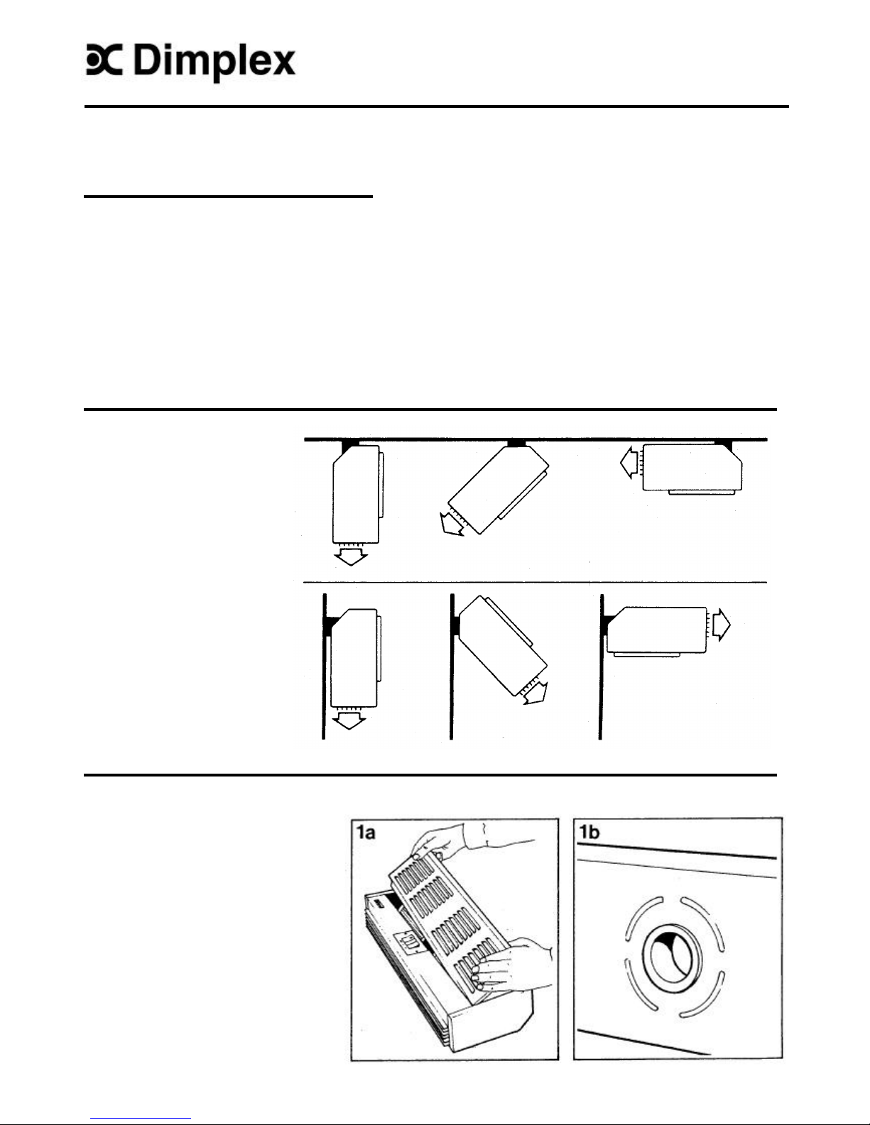
Fixing Positions
Ceiling
mounting
Wall
mounting
Heaters may be mounted end to
end for wide doorways.
Installation
1 (a) Remove front louvered panel by
removing two screws on top flange.
1 (b) If the electricity supply to the heater
is required via conduit entry or through
the remote control switch, it will be
necessary to remove the knockout
around the cable entry bush to provide
a 2Omm diameter hole.
Page 2
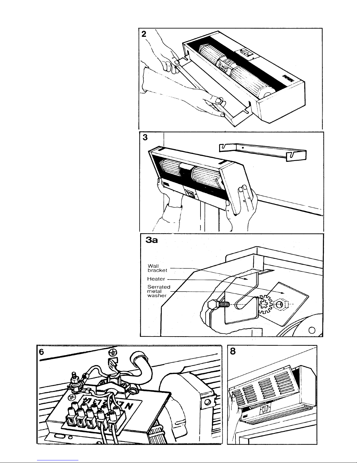
2. Remove the mounting bracket and mark
off the screw positions on the wall or
ceiling. Fix the bracket in position by
making the necessary wall fixings as
described under the heading "Special
Instructions on Fitting Heater to a Wall or
Ceiling".
3. Locate the heater on the mounting
bracket ensuring that the hexagonal
headed screws are fully engaged in the
slots of the bracket.
3a. It is important that the serrated metal
washer is located between the heater wall
fixing member and the wall-mounting
bracket. Adjust heater to the required
angle then firmly tighten the hexagonal
headed screws using the 8mm spanner.
4. Connection to the fixed wiring of the
premises should be done through an
adjacent 20 amp double-pole switch.
5. Connection from the remote control
switch (accessory Ref. No. AC0001) may
be carried out either by conduit entry or
cables run into the heater through a conduit
bush. Refer to circuit diagrams 1 and 2
opposite for removal and substitution of
wires within the appliance.
6. Release the screws securing the mains
supply terminal bracket to gain better
access to the terminal for connection of the
supply cable, which should be carried out
at this point.
WARNING: THIS APPLIANCE MUST BE
EARTHED.
Also ensure that supply cables are of
adequate current carrying capacity and are
protected by a suitable fuse.
If the appliance is mounted in a bathroom,
the appliance should be mounted such that
no part of it can be touched by a person
using a fixed bath or shower. An isolating
switch must be provided outside the
entrance door to the bathroom or be of the
pull-cord type.
7. Re-secure mains supply terminal
bracket,
ensuring that the original screws are used
to do this.
8. Re-secure front cover.
Page 3

Operation
1. Switch on electricity supply to the heater.
2. Switching the switch marked " "
energises blower and illuminates neon
indicator.
3. Select " " and switches marked " xx " and
" xx xx " as required :-
Switch : Cooling
+ xx : half heat
+ xx xx : half heat
+ xx + xx xx : full heat
NOTE: When remote control switch is fitted,
ensure that all three appliance switches are
switched to the "ON" position.
Page 4

Maintenance WARNING: DISCONNECT SUPPLY before carrying out
maintenance.
Thermal Safety Cut outs Two cut -outs are fitted to the heater, situated on the end of the heat exchanger, and
accessible as described below * * . The cut -outs will operate if the appliance
overheats for the following reasons.
a) Air inlet louvered panel obstructed.
b) Air outlet grille obstructed.
c) Fan motor stalled or slow start due to build-up of dirt or fluff.
Rectification procedure:
a) Establish cause and eliminate.
b) Reset thermal cut out (s) by depressing black button on side of cut out as
described in 1 - 3 below.
Air Outlet
1) Pass flat head screwdriver through air Centre Panel Grille
outlet grill to centre panel side of reset button.
2) Press buttons in directions shown to
reset cut -outs. Cut-out clicks when reset.
3) Remove screwdriver carefully.
Cleaning External appearance can be maintained by wiping occasionally with a damp cloth;
for stain removal, a weak soap solution can be applied, then wipe dry.
Internal cleaning should be carried out periodically to maintain the performance of
the heater. Remove the louvered front panel and clean the inside of the heater of
fluff and dust, using a small soft dry brush or vacuum cleaner attachment, taking
extreme care not to disturb internal wiring.
After Sales Service Your Dimplex Air Curtain is guaranteed for one year from date of purchase . We
undertake to exchange or repair free of charge within this period any part found to be
defective due to a manufacturing fault. This guarantee in no way prejudices your
rights under common law.
Should you require after sales service, please get in touch with the supplier through
whom you purchased the appliance, or your nearest service agent.
Please do not initially return a faulty appliance or part of an appliance to us as this
may result in transit damage and or delay in providing service. Let us know your
difficulty, quoting the model number and series letter of the appliance. We will then
take the appropriate action.
This product complies with the European standard for Electromagnetic Compatibility (EMC) ENS5014, EN60555-2 and
EN60555-3 which cover the essential requirements of EEC Directive 891336.
issue 1. 10/10/95
Glen Dimplex UK Limited UK customer helpline (8.00am – 6.00pm Mon-Fri; 8.30am -1.00pm Sat)
Millbrook House
Grange Drive Customer Services: Tel. 0870 7270101
Hedge End Fax. 0870 7270102
Southampton.
Hampshire, SO30 2DF Republic of Ireland 01 8424833
 Loading...