

Dimplex CDFI500-PRO, 6909660400, 6909660300, CDFI1000-PRO Owner's Manual
Owner’s Manual
6909660300
6909660400
Model
CDFI1000-PRO
CDFI500-PRO
7214300200R00
IMPORTANT SAFETY INFORMATION: Always read this manual
rst before attempting to install or use the Opti-myst® cassette. For
your safety, always comply with all warnings and safety instructions
contained in this manual to prevent personal injury or property
damage.
To view the full line of Dimplex products, please visit
www.dimplex.com

2 www.dimplex.com
Table of Contents
Always use a qualied technician
or service agency to repair
this unit.
!
NOTE: Procedures and
techniques that are considered
important enough to
emphasize.
CAUTION: Procedures and
techniques which, if not
carefully followed, will result in
damage to the equipment.
WARNING: Procedures
and techniques which, if not
carefully followed, will expose
the user to the risk of re,
serious injury, or death.
Welcome & Congratulations .................. 3
IMPORTANT INSTRUCTIONS ................ 4
Installation ............................... 6
Operation ............................... 14
Maintenance ............................. 17
Accessories ............................. 18
Warranty ................................ 19
Technical Support ......................... 22
3
Welcome & Congratulations
Thank you and congratulations for purchasing an Opti-myst® cassette
from Dimplex. Please use our convenient online registration page to
record your model and serial numbers for future reference at
www.dimplex.com/register
NO NEED TO RETURN TO THE STORE
Questions with operation or assembly? Require Parts Information?
Product Under Manufacturer’s Warranty?
Contact us at: www.dimplex.com/customer_support
For Troubleshooting and Technical Support
OR Toll-Free 1-888-DIMPLEX (1-888-346-7539)
Monday to Friday 8:00 a.m. to 4:30 p.m. EST
In order to better serve you, please have your model and serial number
ready or register your product online before calling (See above)
Serial Number
Label
Rating Label with
Model Number
Please carefully read and save these instructions.
CAUTION: Read all instructions and warnings carefully before
starting installation. Failure to follow these instructions may result
in a possible electric shock, re hazard and will void the warranty.

4 www.dimplex.com
When using electrical appliances,
basic precautions should always
be followed to reduce the risk of
fire, electric shock, and injury to
persons, including the following:
① Read all instructions before
using the unit.
② Do not operate any unit if the
unit has been dropped or damaged
in any manner. Contact Dimplex
Technical Service at 1-888-346-
7539.
③ Do not use outdoors.
④ Extreme caution is necessary
when any heater is used by or near
children or invalids and whenever
the heater is left operating and
unattended.
⑤ Do not operate any heater after
it malfunctions. Disconnect power
at service panel and have heater
inspected by a reputable electrician
before reusing.
⑥ To disconnect the unit, turn the
controls OFF, disconnect power at
the service panel.
⑦ Do not insert or allow foreign
objects to enter any ventilation or
exhaust opening as this may cause
an electric shock or re, or damage
the heater.
IMPORTANT INSTRUCTIONS
⑧ To prevent a possible re, do not
block air intakes or exhaust in any
manner.
⑨ All electrical heaters have hot
and arching or sparking parts
inside. Do not use in areas where
gasoline, paint, or ammable liquids
are used or stored.
⑩ Do not modify the unit. Use it
only as described in this manual.
Any other use not recommended by
the manufacturer may cause re,
electric shock or injury to persons.
⑪ Do not burn wood or other
materials in the unit.
⑫ Always use a certied electrician
should new circuits or outlets be
required.
⑬ Disconnect the power supply
before performing any cleaning,
maintenance or relocation of the
unit.
⑭ When transporting or storing the
unit, keep in a dry place, free from
excessive vibration and store so as
to avoid damage.

5
SAVE THESE INSTRUCTIONS
WARNING: Remote control
contains small batteries. Keep away
from children. If swallowed, seek
medical attention immediately.
WARNING: Do not install
battery backwards, charge, put
in re or mix with used or other
battery types - may explode or leak
causing injury.
!
NOTE: Changes or
modications not expressly
approved by the party responsible
for compliance could void user's
authority to operate the equipment.
IMPORTANT INSTRUCTIONS
CAUTION
RISK OF ELECTRIC SHOCK
DO NOT OPEN
NO USER-SERVICEABLE PARTS INSIDE
CAUTION: This equipment has been
tested and found to comply with the limits
for Class B digital device, pursuant to part
15 of the FCC Rules. These limits are
designed to provide reasonable protection
against harmful interference in a residential
installation. This equipment generates, uses
and can radiate radio frequency energy
and, if not installed and used in accordance
with the instructions, may cause harmful
interference to radio or television reception,
which can be determined by turning the
equipment OFF and ON, the user is
encouraged to try to correct the interference
by one or more of the following measures:
• Reorient or relocate the receiving
antenna.
• Increase the separation between the
equipment and the receiver.
• Connect the equipment into an outlet on
a circuit different from that to which the
receiver is connected.
• Consult the dealer or an experienced
radio/TV technician for help.
This device complies with Part 15 of the
FCC Rules. Operation is subject to the
following two conditions: (1) This device
may not cause harmful interference, and
(2) this device must accept any interference
received, including interference that may
cause undesired operation.
FCC CAUTION: Any changes or
modications not expressly approved by
the party responsible for compliance could
void the user’s authority to operate this
equipment.
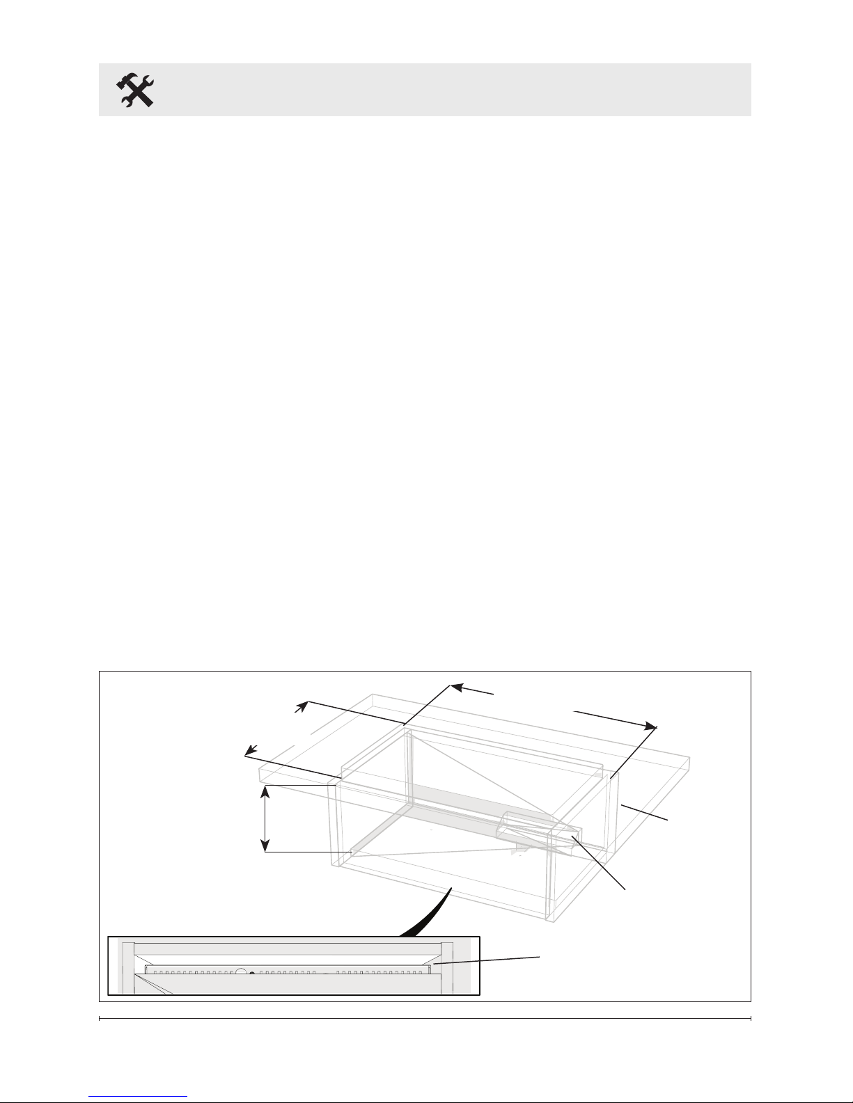
6 www.dimplex.com
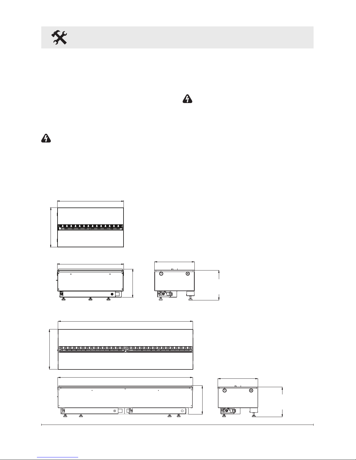
8.50 in. (216 mm)
40.08 in. (1018 mm)
Logset: 13.94 in. (353 mm)
11.94 in. (303 mm)
40.08 in. (1018 mm)
Media Plate: 11.94 in. (303 mm)
8.50 in. (216 mm)
20.04 in. (509 mm)
20.04 in. (509 mm)
11.94 in. (303 mm)
Logset: 13.94 in. (353 mm)
Adjustable from
9.13 in. (232 mm)
to 9.63 in. (245 mm)
Media Plate: 11.94 in. (303 mm)
CDFI1000P
CDFI500P
Adjustable from
9.13 in. (232 mm)
to 9.63 in. (245 mm)
Installation
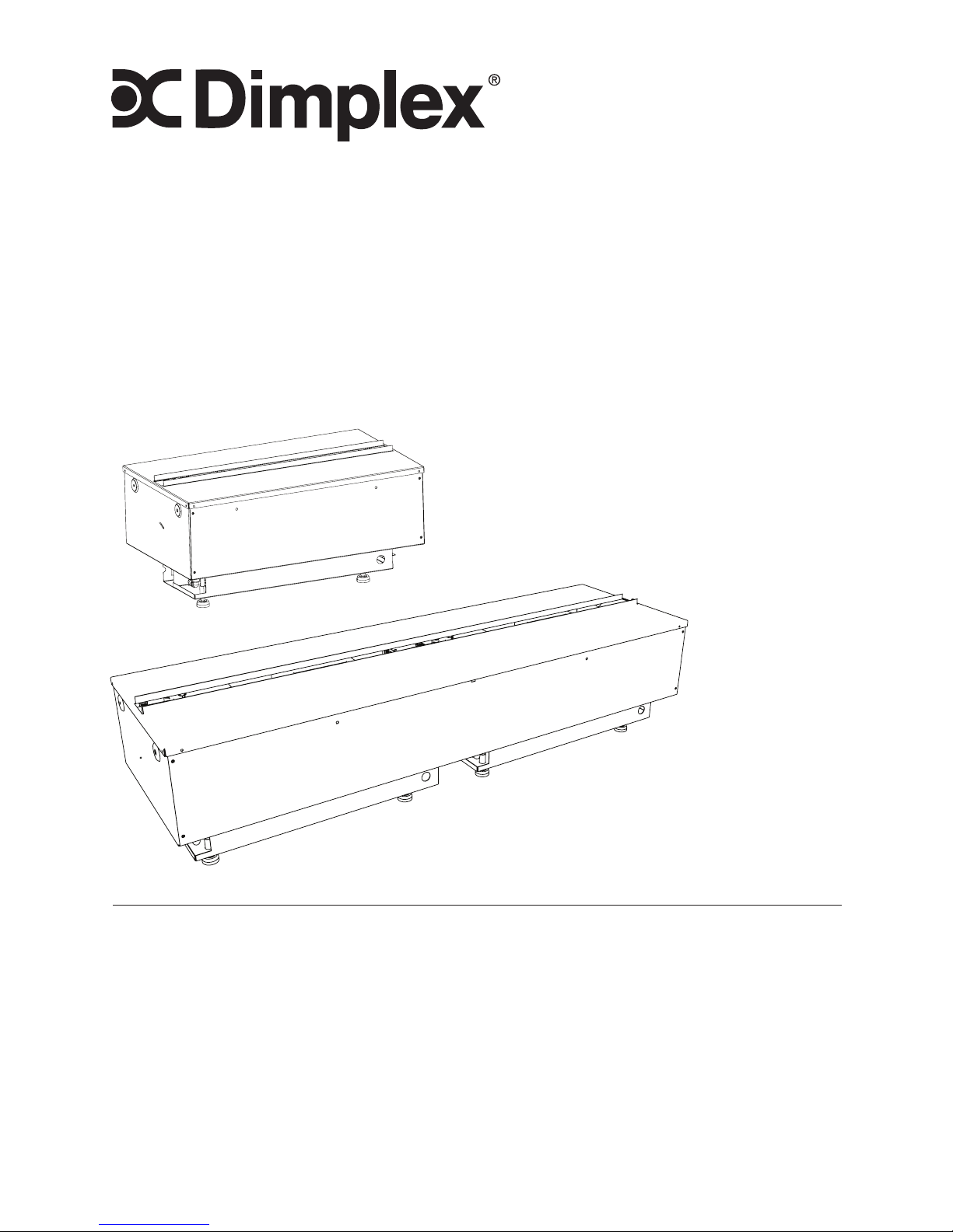
The CDFI1000-PRO and
CDFI500-PRO are supplied in an
assembled state and are designed
to be permanently installed. The
units come ready for hardwire
installation and the use of the
water rell containers.
WARNING: Construction and
electrical outlet wiring must
comply with local building codes
and other applicable regulations
to reduce the risk of re, electric
shock and injury to persons.
WARNING: To reduce the risk of
re, do not store or use gasoline
or other ammable vapours or
liquids in the vicinity of the unit.
!
NOTE: A 15 Amp, 120 Volt
circuit is required. A dedicated
circuit is preferred but not essential
in all cases. A dedicated circuit will
be required if, after installation,
the circuit breaker trips or the fuse
blows on a regular basis when the
cassette is operating. Additional
appliances on the same circuit may
exceed the current rating of the
circuit breaker.
!
NOTE: When prepar-
ing the opening for the unit
¼ in. (6.4 mm) of clearance
should be maintained from
each surface to ensure easy
installation.
Product Dimensions
CDFI500-PRO
CDFI1000-PRO
7
Installation
WARNING: Failure to install the
cassette as instructed below
may result in damage to the
equipment and or may expose
the user to the risk of re,
serious injury, illness or death.
WARNING: Do not attempt to
wire your own new outlets or
circuits. To reduce the risk of
re, electric shock or injury to
persons, always use a licensed
electrician.
WARNING: Ensure that the
On/Off switch is set to the OFF
position (refer to Operation
section) and that the circuit on
which the unit is to be installed
has the power cut off at the
service panel until installation is
complete.
!
NOTE: Please read all
instructions before installing.
Cassette Plumbing
The units come equipped with rell
containers for manual lling of the
reservoir. The unit can be hard
plumbed with the Dimplex
plumbing accessory kit CDFIPLUMB-KIT, available from
your local Dimplex dealer, or with
standard 1/4 in (6.4mm) tubing,
using the information outlined
below.
!
NOTE: The plumbing accessory
kit is designed for use with copper
piping.
CAUTION: Ensure that all
plumbing connections meet local
plumbing code requirements.
CAUTION: Ensure that the
location of the plumbing connection
allows for easy access to allow
for shutoff during scheduled
maintenance.
1. Locate a cold water line in the
vicinity of the desired location
of the cassette.
!
NOTE: Normal tap water can
be used in the Opti-myst® as long
as the tap water is not considered
to be hard water. In the event
your tap water is hard, softened or
ltered water is recommended.
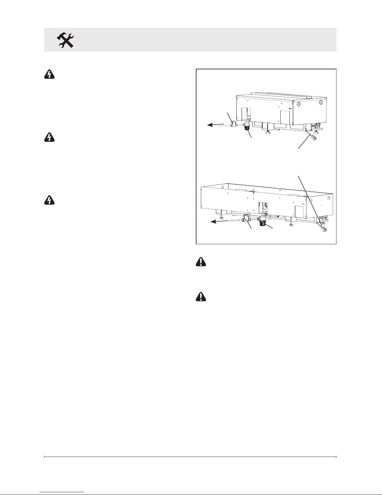
Figure 1
Ball
Valve
To water
source
Ball
Valve
To water
source
CDFI500-PRO
CDFI1000-PRO
Filter
Filter
2 pin wire for
connecting to
optional Heater
8 www.dimplex.com
Installation
2. Turn OFF the main water
supply and drain the line of any
standing water (if possible),
before proceeding to tie into
the water line.
!
NOTE: Once the new plumbing
connections are complete ensure
that the lines are ushed to prevent
any debris from going into the unit.
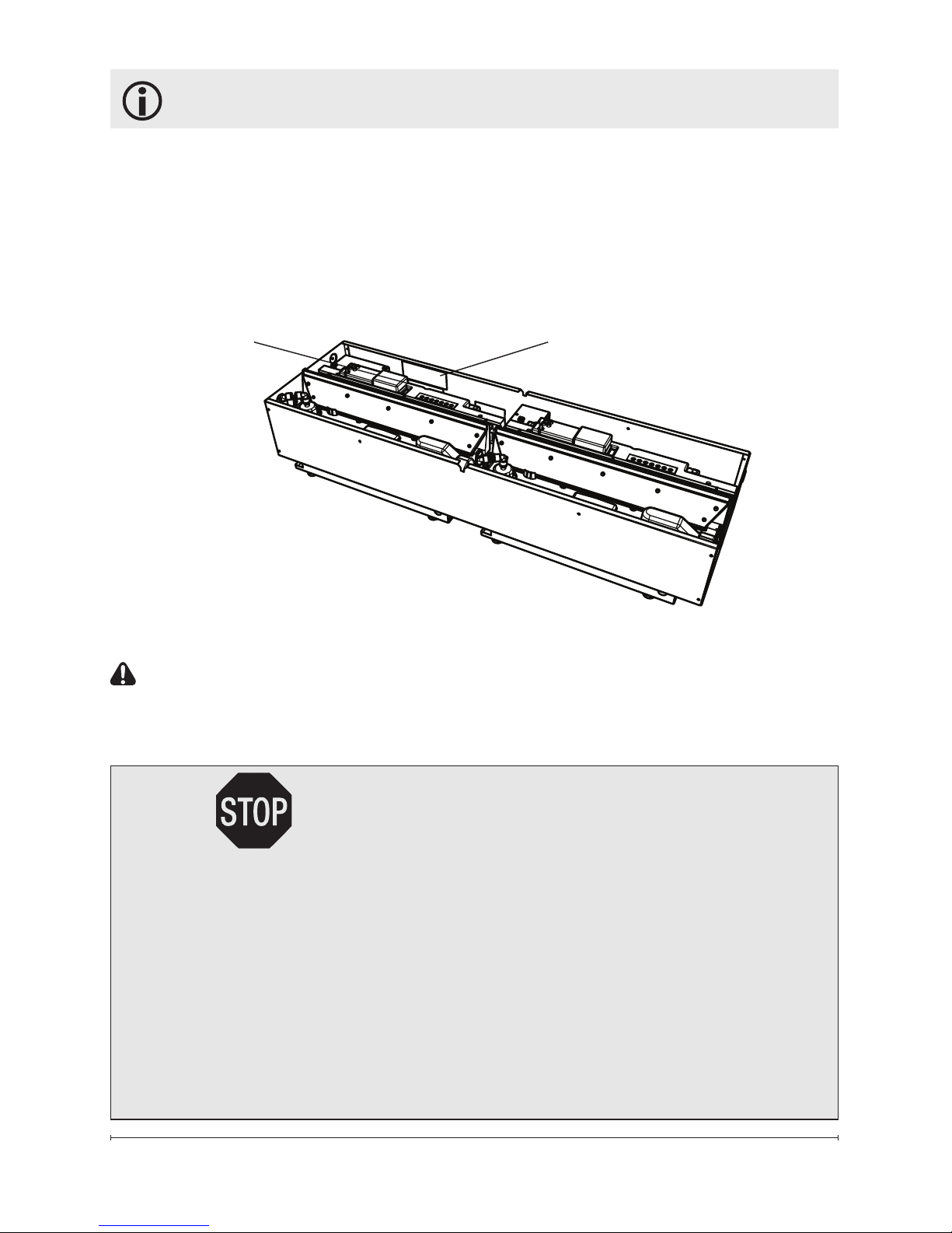
3. On the cassette, remove the
top cover assemblies (Figure
10, page 18) and prime each of
the water reservoirs with 33.5
oz (1L) of water.
4. Replace the top cover
assemblies and ensure that the
two plumbing caps are securely
attached to the top cover of the
water reservoirs. (Figure 10,
page 18)
5. Locate the ball valve located
in the bottom center of the unit
(near the back). (Figure 1)
6. Attach one end of the ¼ in
(6.4 mm) tubing to the ball
valve. Insert the tubing into the
ball valve tting so that it is fully
inserted (approximately ½ in
(12 mm)).
!
NOTE: Ensure that the end of
the tubing is cut square, to prevent
leaking.
7. Route the tubing to the area of
the water source.
8. Verify that all of the
connections are fully inserted,
and begin opening each of the
valves, ensuring that no leaks
are present.
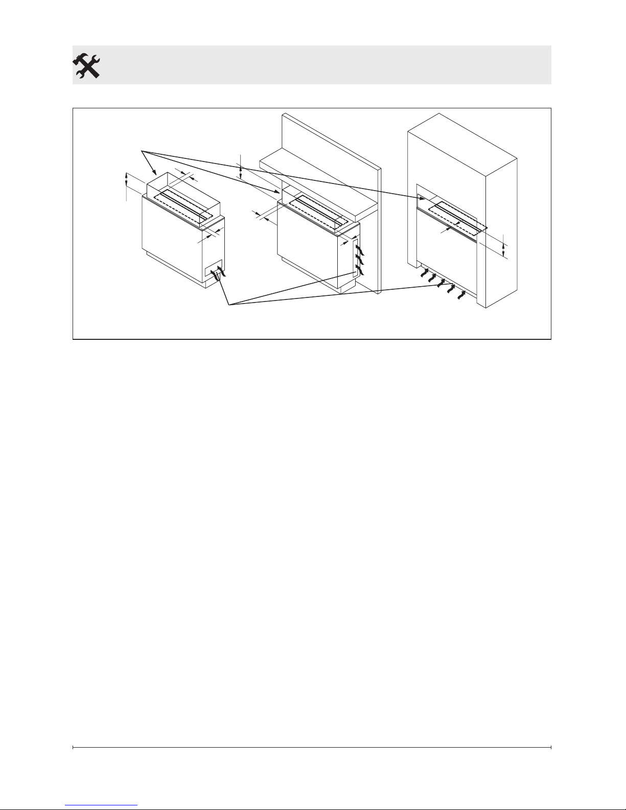
Figure 2
Adjustable from
9 in to 9½ in
(229 mm to 241 mm)
Fresh Air Inlet
CDFI500-PRO: 40 in2 (258 cm2)
CDFI1000-PRO: 80 in2 (516 cm2)
Exit for Electrical
CDFI500-PRO: 20⅜ in (518mm)
CDFI1000-PRO: 40⅜ in (1025mm)
Installation
Surface
Media Plate: 12¼ in (311mm)
Log Set: 14¼ in (362mm)
9
Installation
Connecting Multiple Units
Together
When connecting multiple units
together, the plumbing should be
constructed in a manifold style
conguration, sized appropriately
for the number of units that are
being installed so a consistent
volume water and pressure is being
supplied to each unit.
New Construction
When determining a location for the
Opti-myst® cassette, ensure that the
unit will not be susceptible to drafts,
vents, ceiling fans and other air
currents. Similar to a candle, large
movements of air will affect the
unit’s ability to create and maintain
the ame effect.
If the desired location is susceptible
to signicant air movement, i.e.
air vents, the different installation
options illustrated in Figure 3 can
be used. It is important that the
surface surrounding the top of the
cassette have at least a 3 in
(72 mm) clearance from any vertical
surface and the barrier be 10 in
(254 mm) high from the installation
surface, to ensure optimal ame
production.
!
NOTE: It is recommended
that during drywall installation
and nishing the media plate be
installed with the provided bag
to prevent dust and debris from
entering the unit.
1. Use studs to frame an
enclosure with the following
minimum internal/opening
dimensions. Note that the
Media Plate (supplied) and Log
Set (optional) require different
opening widths - see Figure 2.
!
NOTE: A fresh air inlet that
is a minimum of 80in2 (516 cm2)
(77 mm)
3 in.
10 in.
(254 mm)
10 in.
(254 mm)
10 in.
(254 mm)
(77 mm)
3 in.
(77 mm)
3 in.
(77 mm)
3 in.
(77 mm)
3 in.
Figure 3
Air Inlet
CDFI500-PRO: 40 in2 (258 cm2)
CDFI1000-PRO: 80 in2 (516 cm2)
Glass, plexi-glass, etc.
10 www.dimplex.com
Installation
for the CDFI1000-PRO and 40in2
(258 cm2) for the CDFI500-PRO,
is required for optimum mist
production. The air intake must
allow for air to reach the underside
of the Opti-myst Cassette
(Figure 2 & 3). If installing into
the Opti-myst Pro Box Heater
(optional), no additional air intake
is required. The Opti-myst Pro Box
Heater is designed with air intakes
included.
For optimal performance, a
clearance of 18 in (457 mm)
between the installation surface
and any surface above should be
maintained. A minimum clearance
of 16 in (405 mm) must be
maintained.
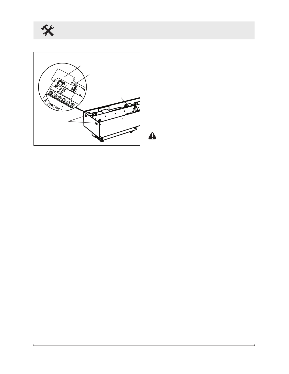
2. In the back left corner of
the unit, locate and remove
the electrical cover plate, by
removing the two securing
screws.
3. Install a ⅜ in (10 mm) or ½ in
(13 mm) cable connector, not
included, suitable for mounting
in a ⅞ in (22 mm) hole, to the
cable plate and feed the supply
cable through the connector.
The cable plate can be
removed by removing the two
securing screws on either side,
to allow for easier access.
CAUTION: Use two conductor,
non-metallic sheath cable with
ground wire (3 wires total) for the
incoming power supply on the
cassette. Use appropriate wire to
meet local and national electrical
codes for rated power.
!
NOTE: When installing multiple
units in the same vicinity they will
need to be wired in parallel.
!
NOTE: The Opti-myst® cassette
is designed to allow for installation
of a wall switch to control the
incoming power to the unit.
4. Connect the black wire (live)
from the unit to the live from
the power supply.
5. Connect the white wire
(neutral) from the unit to the
neutral wire from the power
supply.
6. Connect the green wire
(ground) from the unit to the
ground wire from the power
supply.
Cable Plate
Electrical Cover Plate
Holes for
securing to
framing
Cord Outlet
for Tethered
Controller
Figure 4

11
7. Place all connectors inside
the unit and secure the cable
clamp to unit, making sure that
the cable clamp grips only the
jacket of service cable.
WARNING: Ensure the power
wiring is not installed so that it
is pinched or against a sharp
edge and ensure that the power
wiring is stored or secured to
avoid tripping or snagging to
reduce the risk of re, electric
shock or injury to persons.
8. Install the unit into the roughed
in framing ensuring that the unit
is resting on two framing sills,
one at the front and one at the
back or a level surface. Ensure
an air opening is maintained.
9. Level the housing - right to left
and front to back, using the
adjustable feet on the bottom of
the unit.
10. Secure the unit to the
permanent framing on either
end through a minimum of two
holes (Figure 4).
Operation Preparation
1. After the surrounding area has
been dry walled and nished,
remove the media plate from
the unit.
2. Unwrap the tethered controller
and ensure that the wire is
lead through the opening in
Installation
the bottom of the unit where
the hard plumbing attaches.
(Figure 4)
3. Locate the tethered controller
so that:
a) it can be easily accessed, if
being used as the main controls,
or
b) it is not obscured by either
bricks, stone or sheet metal so
that the signal that is sent from
the remote control can be easily
picked up.
4. Initialize the tethered controller
to the remote (see operation
section, page 16).
5. Fill the unit:
• Rell Containers - remove
the ll cap assemblies from
the inlet to the reservoir tanks,
then install the rell containers.
(Figure 10, page 18)
!
NOTE: During initial
installation, the Rell Container
should be relled after the
Reservoir has lled to ensure
the maximum operating time.
Rell Container holds 42 oz.
(1.25L).
• Hard Plumbed - prime each of
the water reservoirs with 33.5 oz
(1L) of water.
!
NOTE: Normal tap water can
be used in the Opti-myst® as long
as the tap water is not considered
12 www.dimplex.com
Installation
to be hard water. In the event your
tap water is hard, you may use
softened water or distilled water
with ⅛ tsp. of salt (0.5 mL) added
to the water reservoir. (The use
of additional salt should only be
when you notice that the unit is not
producing mist as expected.)
6. Install the media plate or logset
accessory on top.
!
NOTE: If the intention is to
accessorize the unit with something
other than just the media plate or
logset, ensure that media used
does not have the ability to create
small particles that may fall into the
unit or have a overall weight above
10 lbs (4.5 kg) for the CDFI500PRO and 20 lbs (9 kg) for the
CDFI1000-PRO.
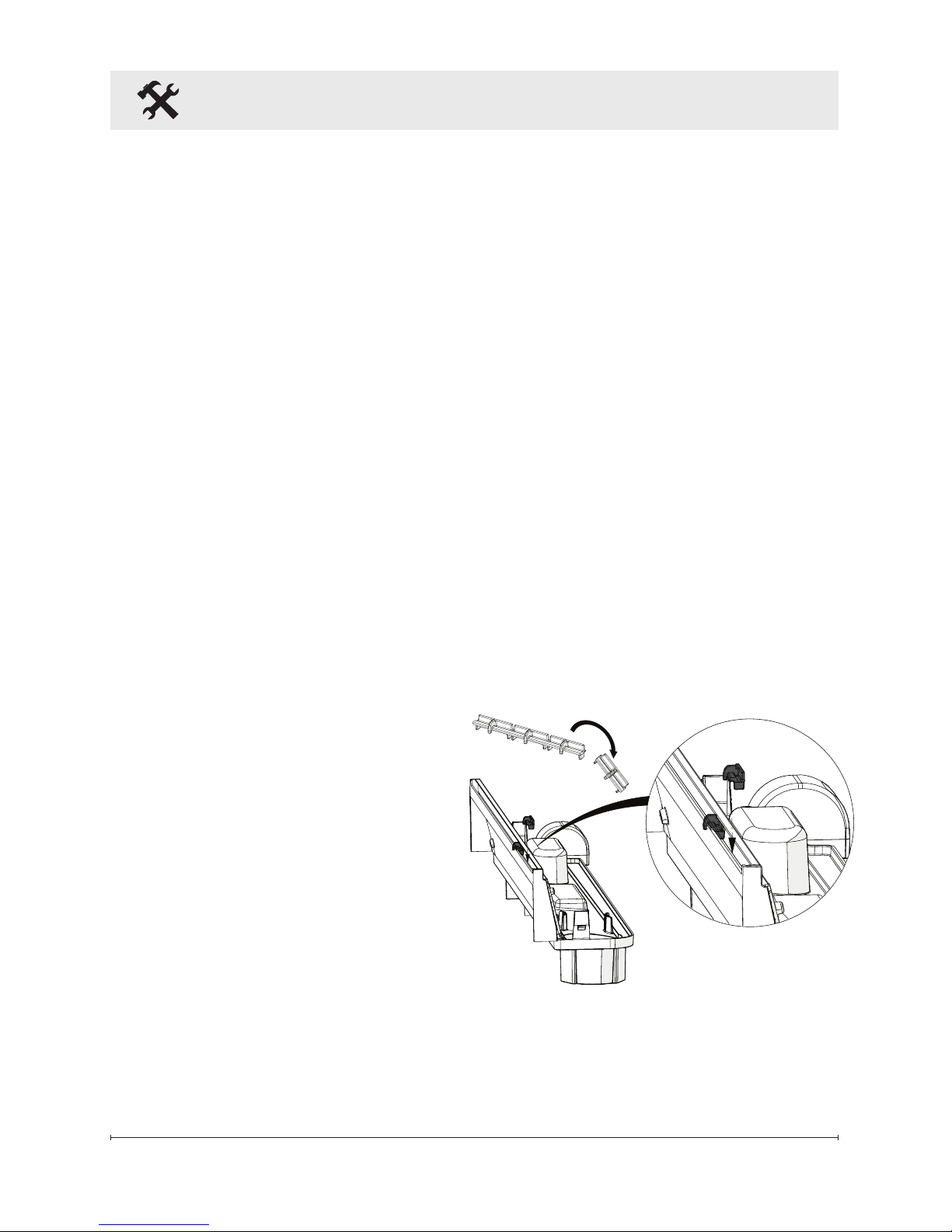
Customize Flame
The CDFI500-PRO and CDFI1000PRO come with inserts that
allow you to customize the look
of the ame. Refer to Figures 5
and 6. To use the spacers, rst
break them along the break line
(Figure 5). Second, insert into the
nozzle at desired locations. It is
recommended to place them under
any media that crosses through the
ame, for example, logs.
To use the slots, insert them into
the nozzle (Figure 6). A total of
3 slot inserts can be used in each
nozzle.
Figure 5
13
Installation
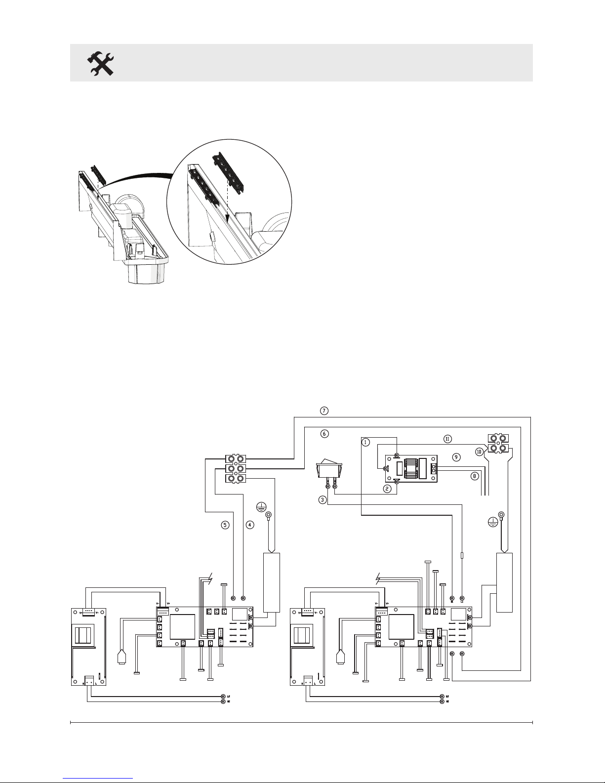
Wiring Diagram
Bathroom Installation
This unit must be protected by a
GFI circuit. If a receptacle is used it
must be readily accessible.
To prevent electrical shock this
unit is an electrical appliance
that is not watertight and must be
installed as to prevent water from
entering the unit. This unit must be
installed away from showers, tubs,
etc. Never locate replace over a
bathtub or other water containers.
Keep towels and
other combustible materials
3 feet (0.9 m) away from the top of
the unit.
Figure 6
TRANSDUCER 1
FUEL BED
SOLENOID
FILL1
TRANSDUCER 1
FUEL BED
SOLENOID
MAIN
SOLENOID
FILL1
2 WAY
REED
3 WAY
REED
SWITCH
BOARD
LED
DRIVER
BOARD
2 WAY
REEDBTRECEIVER
LED
DRIVER
BOARD
RELAYRELAY
N1
N2
N3
N4
L1
N1
24V INPUT 24V INPUT
L1
L2
L3
L4
N1
N2
N3
N4
L1
L2
L3
N3 L3
L4
HEAT
CONTROL PCB
SPEAKER
BLUE
WHITE
BLACK
GREEN / YELLOW
BROWN
DC FAN
MOTOR
DC FAN
MOTOR
COMMUNICATION LINK
ELEMENT
ELEMENT
3 WAY
REED
SWITCH
BOARD
CDFI500-PRO
14 www.dimplex.com
Operation
WARNING: This unit must be
properly installed before it is
used.
There are three different control
options available for the unit:
manual (under the media), tethered
controller (must be connected to the
unit) and a remote control.
The CDFI1000-PRO unit has two
separate internal modules that are
controlled by the settings entered
on the left side (primary). Finer
adjustment can be done using the
controls on the right module to have
both modules operating at the same
level (secondary).
!
NOTE: When the unit is used in
an environment where background
noise is very low, it may be possible
to hear a sound which is related to
the operation of the ame effect.
This is normal and should not be a
cause for concern.
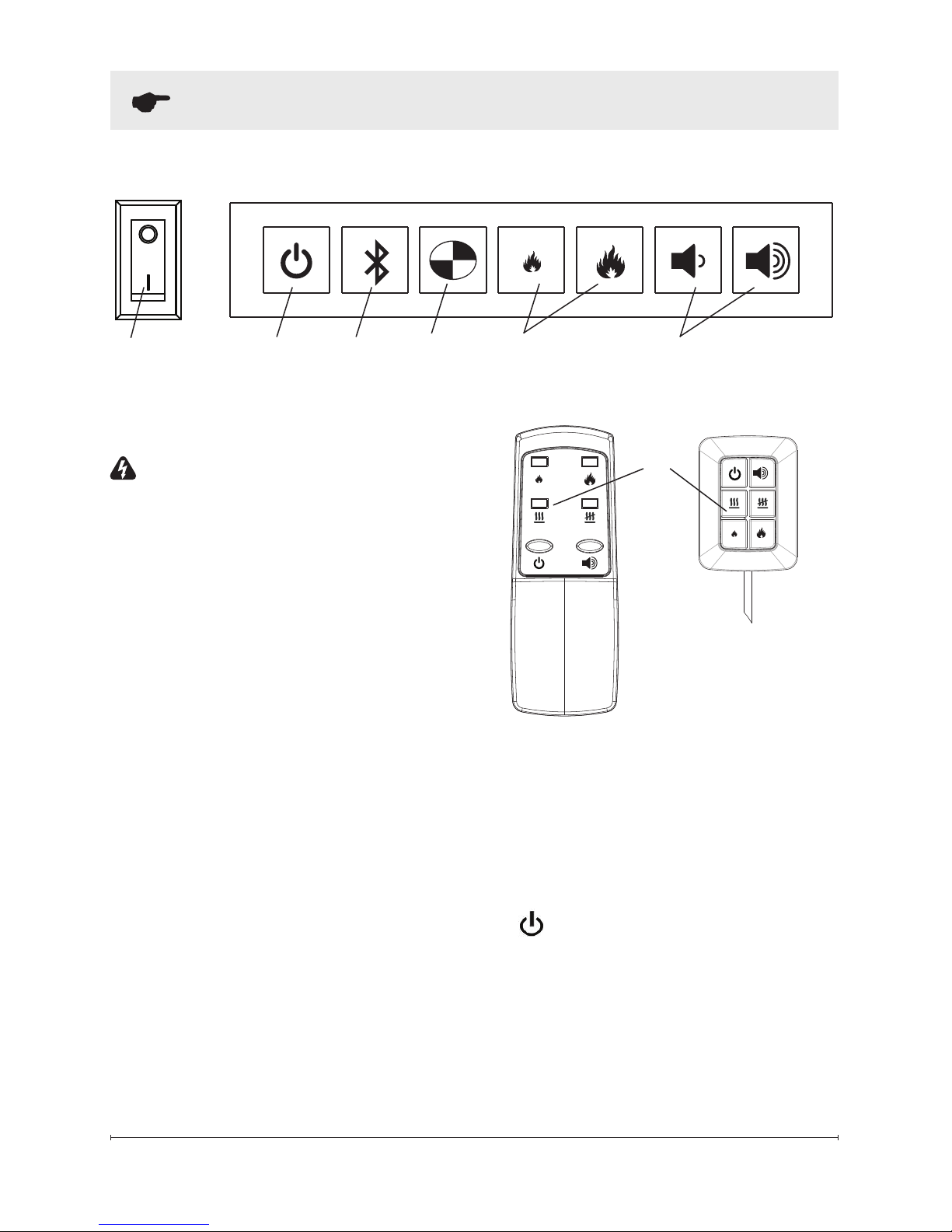
Controls
A. On/Off Switch
Supplies power to the unit.
B.
Standby
Turns ame effect on or puts the
unit into standby mode.
!
NOTE: When the unit is rst
turned on the lights will come on
and mist will appear 45 seconds
later.
B
A
C D
Figure 7
E F
Figure 8
Remote Control
Tethered
Controller
G

15
C. Bluetooth
Required for initializing the remote
together with the Cassette, see
initialization instructions for more
detail.
D. Test Mode
Used for troubleshooting issues
- outlined in detail in the service
manual which can be found on
www.dimplex.com/customer_
support.
E. Flame Intensity Control
Adjusts the intensity of the ame
and smoke effect when the unit has
been activated.
Pressing the will decrease the
ame effect and pressing the will
increase the ame effect.
!
NOTE: A few moments will be
required between adjustment and a
change to the ame effect.
!
NOTE: During normal
operation it is expected to see
some condensation of water on
the media plate. This will vary
depending on ambient conditions
and should be considered normal.
!
NOTE: When the water tank is
empty, the ame effect shuts OFF
and the LED's will blink twice,
continuously.
!
NOTE: On the CDFI1000-
PRO, each side of the ame can
be adjusted using the on-board
controls.
F. Volume Control
Adjusts the volume of the wood re
sound effects.
On the unit: Pressing the
will decrease the volume and
pressing the will increase the
volume.
On the Remote and Tethered
Controls: Pressing the will
turn the volume ‘ON’ ( I ) and
‘OFF’ ( O ).
G. Heat On/Off
Turns the optional heater
accessory ‘ON’ or ‘OFF’ .
!
NOTE: The 2 pin heater wire
(Figure 1) must be connected to
the heater for this control to work.
Remote Control
The tethered controller can be used
in the same manner as the remote
but houses the blue tooth receiver
for communication with the remote.
The tethered controller must be
connected to the unit and On/Off
Switch must be in the ‘ON’ ( I )
position in order for the remote to
operate.
Operation
16 www.dimplex.com
6. If the synchronization was
successful the LED's will blink
5 times and beep 5 times then
the unit will go to Standby.
This will synchronize the remote
control and the tethered controller.
!
NOTE: It is possible to
synchronize up to 5 units to one
remote control.
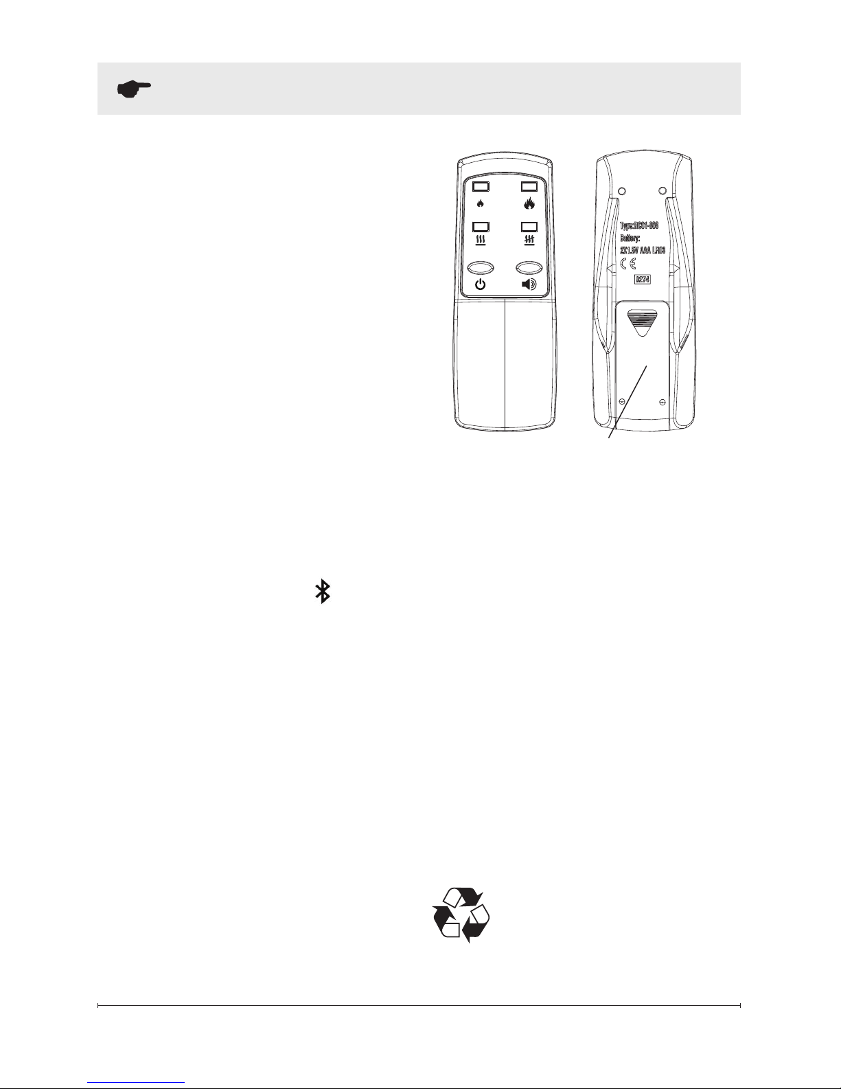
Battery Replacement
To replace the battery:
1. Slide battery cover open on the
remote control (Figure 9).
2. Install two 1.5 Volt (AAA)
battery in the battery holder.
3. Close the battery cover.
Battery must be recycled or
disposed of properly. Check
with your Local Authority or
Retailer for recycling advice in your
area.
Battery Cover
Figure 9
!
NOTE: To operate correctly the
remote control must be initialized
with the unit.
Remote Control Initialization/
Reprogram
In order for the remote to
communicate with the unit the blue
tooth must be setup, as outlined
below:
1. Verify that the tethered
controller is connected
correctly - the red light on the
controller will be illuminated.
2. Place the On/Off Switch
(Figure 7A) in the ON ( I )
position.
3. Press the Bluetooth
initialization button on the
Primary controls (left side).
4. The unit will begin to beep
and turn the lights ON and
OFF every 2 ½ seconds to
indicate that the unit is in
synchronization mode.
5. Within 20 seconds of pressing
the blue tooth button, press
any button on the remote
control (Figure 9).
!
NOTE: You will have only 20
seconds to perform this last step.
Failure to do so will result in these
steps needing to be followed again.
Operation

17
WARNING: Disconnect
power before attempting any
maintenance or cleaning to
reduce the risk of re, electric
shock or damage to persons.
Filling the water tank
When the water tank is empty,
the ame effect will shut OFF and
the LED's will blink continuously.
Follow these steps to rel the
tank.
CAUTION: Allow at least ve
minutes for components to cool
before disassembling the unit to
rell.
1. Gently remove the media and
place it carefully on the ground.
2. Turn the On/Off switch to the
OFF position (O) (Figure 7A)
3. Remove the rell container by
lifting upwards and outwards.
4. Rell the container with tap
water.
!
NOTE: Normal tap water can
be used in the Opti-myst® as long
as the tap water is not considered
to be hard water. In the event
your tap water is hard, you may
use softened water or distilled
water with ⅛ tsp. of salt (0.5 mL)
added to the water reservoir. (The
use of additional salt should only
be when you notice that the unit is
not producing mist as expected.)
5. Screw the cap back on, do not
overtighten.
6. Return the rell container to the
sump, with the tank cap facing
down and the at side of the
tank facing outward.
7. Turn the On/Off switch to the
ON position ( I ). (Figure 7A)
8. Gently place the top tray back
into position.
If you do not intend on using
the unit for longer than 2 weeks,
empty and drain the unit of water,
and dry all of the water containing
components.
Transducer Replacement
After prolonged usage the ability
for the unit to produce mist may
become reduced. When this
occurs the replacement of the
transducer may be required.
This unit comes with additional
transducer(s), located within the
unit, which can be installed when
this occurs.
!
NOTE: There is a small tab
that holds the transducer in place,
that needs to be released before
it can be removed.
Maintenance
18 www.dimplex.com
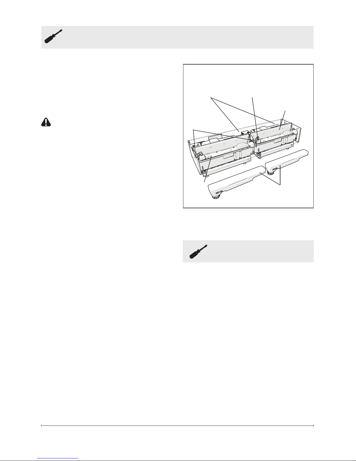
Maintenance
Figure 10
Cleaning
It is recommended that the top
cover assembly, sump and transducer
are cleaned with soap and water
on a biweekly basis.
CAUTION: Do not put plastic
components in the dishwasher.
The water lter (Figure 1) should
be rinsed out on a regular basis
to remove any collected particles.
Filter Cleaning
The air lters can be removed
and gently rinsed with water to
clean and dried on a towel before
reinstalling.
!
NOTE: Replace the lter
so that the course black lter is
facing the back of the unit.
Surface Cleaning
Use a warm damp cloth only to
clean surfaces of the unit. Do not
use abrasive cleaners.
!
NOTE: If you need to move
the unit ensure that all of the
components that contain water
have been emptied before
relocating.
Servicing
Except for installation and
cleaning described in this
manual, an authorized service
representative should perform
any other servicing.
Sump
Top Cover
Assembly
Accessories
Release
Tabs
Please contact your local dealer
for genuine Dimplex accessories.
Example: logsets, plug kit, heater
and plumbing kits.
Rell Containers
Plumbing
Caps
Air
Filters

19
Warranty
Two Year Limited Warranty
Products to which this limited warranty
applies
This limited warranty applies to your newly
purchased Dimplex cassette and to newly
purchased Dimplex replace surrounds
(mantels) and trims. This limited warranty
applies only to purchases made in any
province of Canada except for Yukon
Territory, Nunavut, or Northwest Territories
or in any of the 50 States of the USA (and
the District of Columbia) except for Hawaii
and Alaska. This limited warranty applies
to the original purchaser of the product
only and is not transferable.
Products excluded from this limited
warranty
Logset assemblies are only covered for
transportation to the end user and will
not be covered if damage occurs during
normal operation and/or maintenance.
Products purchased in Yukon Territory,
Nunavut, Northwest Territories, Hawaii,
or Alaska are not covered by this limited
warranty. Products purchased in these
States, provinces, or territories are sold
AS IS without warranty or condition of
any kind (including, without limitation,
any implied warranties or conditions of
merchantability or tness for a particular
purpose) and the entire risk of as to the
quality and performance of the products is
with the purchaser, and in the event of a
defect the purchaser assumes the entire
cost of all necessary servicing or repair.
What this limited warranty covers and for
how long
Products, other than replace surrounds
(mantels) and trims, covered by this
limited warranty have been tested and
inspected prior to shipment. Subject to
the provisions of this warranty, Dimplex
warrants such products to be free from
defects in material and workmanship for
a period of 2 years from the date of the
rst purchase of such products as follows:
(a) a repair or replacement warranty on
defective products or parts, including
in-home services, for the rst year
following the date of rst purchase; and (b)
thereafter, a replacement of parts warranty
on defective products and parts (with no
in-home services) for the 1 year period
commencing on the rst anniversary of
rst purchase and ending on the second
anniversary of the date of rst purchase.
Dimplex replace surrounds (mantels)
and trims covered by this limited warranty
have been tested and inspected prior to
shipment and, subject to the provisions
of this warranty, Dimplex warrants such
products to be free from defects in
material and workmanship for a period of
1 year from the date of rst purchase of
such products. Warranty services do not
include in-home services.
The limited 2 year warranty period for
products other than replace surrounds
(mantels) and trims and the limited 1 year
warranty period for replace surrounds
(mantels) and trims also applies to any
implied warranties that may exist under
applicable law. Some jurisdictions do not
allow limitations on how long an implied
warranty lasts, so the above limitation may
not apply to the purchaser.
What this limited warranty does not cover
This limited warranty does not apply to
products that have been repaired (except
by Dimplex or its authorized service
representatives) or otherwise altered. This
limited warranty does further not apply
to defects resulting from misuse, abuse,
accident, neglect, incorrect installation,
improper maintenance or handling, or
operation with an incorrect power source.
What you must do to get service under
this limited warranty
Defects must be brought to the attention of
Dimplex Technical Service by contacting

20 www.dimplex.com
Warranty
Dimplex at 1-888-DIMPLEX
(1-888-346-7539), or 1367 Industrial
Road, Cambridge Ontario, Canada
N3H 4W3. Please have proof of purchase,
catalogue/model and serial numbers
available when calling. Limited warranty
service requires a proof of purchase of the
product.
What Dimplex will do in the event of a
defect
In the event a product or part covered
by this limited warranty is proven to be
defective in material or workmanship
during (i) the 2 year limited warranty
period for products other than replace
surrounds (mantels) and trims, and (ii)
the 1 year limited warranty period for
surrounds (mantels) and trims, you have
the following rights:
• Limited warranty service will be
performed solely by dealers or service
agents of Dimplex authorized to provide
limited warranty services.
• For products (other than surrounds
(mantels) and trims) for the period
ending at midnight on the rst
anniversary of the date of rst
purchase, Dimplex will in its sole
discretion either repair or replace
such defective product or part
without charge. If Dimplex is unable
to repair or replace such product or
part, or if repair or replacement is not
commercially practicable or cannot be
timely made, Dimplex may, in lieu of
repair or replacement, choose to refund
the purchase price for such product
or part. This limited warranty entitles
the purchaser to on-site or in-home
warranty services. Accordingly, Dimplex
will be responsible for all labour and
transportation costs associated with the
repair or replacement of the product
or part except as follows: (i) charges
may be levied for travel costs incurred
to travel to the purchaser’s site where
the product is located if the purchaser’s
site is beyond 30 miles (48 km) from
the closest service depot of Dimplex’s
dealer or service agent; and (ii) the
purchaser is solely responsible for
providing clear access to all serviceable
parts of the product.
• For products (other than surrounds
(mantels) and trims) for the period
commencing at 12:01 a.m. on the day
after the rst anniversary of the rst
purchase and ending at midnight on
the second anniversary of the date
of rst purchase, this limited warranty
entitles the purchaser to replacement
parts only without charge. If Dimplex
is unable to replace such part, or
if replacement is not commercially
practicable or cannot be timely made,
Dimplex may, in lieu of replacement,
choose to refund the purchase price
for such part. The purchaser shall
not be entitled to on-site or in-home
warranty services. The purchaser
shall be responsible for all expenses
incurred for the removal of the part
and installation of the replacement part
including, without limitation, all shipping
costs and transportation costs to and
from the authorized dealer’s or service
agent’s place of business and all labour
costs. Such costs shall not be the
responsibility of Dimplex.
• For surrounds (mantels) and trims
for the period ending at midnight
on the rst anniversary of the
date of rst purchase, Dimplex will
in its sole discretion either repair or
replace such defective surrounds
(mantels) and trims or part thereof
without charge. If Dimplex is unable
to repair or replace such product or
part, or if repair or replacement is not
commercially practicable or cannot
be timely made, Dimplex may, in lieu
of repair or replacement, choose to
 Loading...