

Page 1
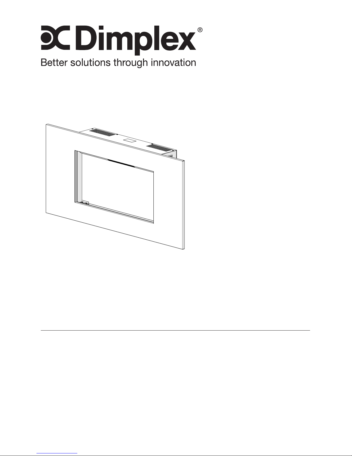
Owner’s Manual
Model
6908760100
7212640100R00
IMPORTANT SAFETY INFORMATION: Always read this manual rst
before attempting to install or use this replace. For your safety, always
comply with all warnings and safety instructions contained in this manual
to prevent personal injury or property damage.
To view the full line of Dimplex products, please visit
www.dimplex.com
Note: Trim may vary.
Page 2
2 www.dimplex.com
Table of Contents
Always use a qualied technician
or service agency to repair
this replace.
!
NOTE: Procedures and
techniques that are considered
important enough to
emphasize.
CAUTION: Procedures and
techniques which, if not
carefully followed, will result in
damage to the equipment.
WARNING: Procedures
and techniques which, if not
carefully followed, will expose
the user to the risk of re,
serious injury, or death.
Welcome & Congratulations .................. 3
IMPORTANT INSTRUCTIONS .................4
Quick Reference Guide ...................... 7
Fireplace Installation ....................... 7
Wall Hanging Instructions ....................8
Media Installation ..........................10
Operation ................................ 12
Maintenance ............................. 14
Warranty ................................ 15
Replacement Parts ........................ 17
Page 3
3
Welcome & Congratulations
Thank you and congratulations for choosing to purchase an electric
replace from Dimplex, the world leader in electric replaces.
Please carefully read and save these instructions.
CAUTION: Read all instructions and warnings carefully before
starting installation. Failure to follow these instructions may result in
a possible electric shock, re hazard and will void the warranty.
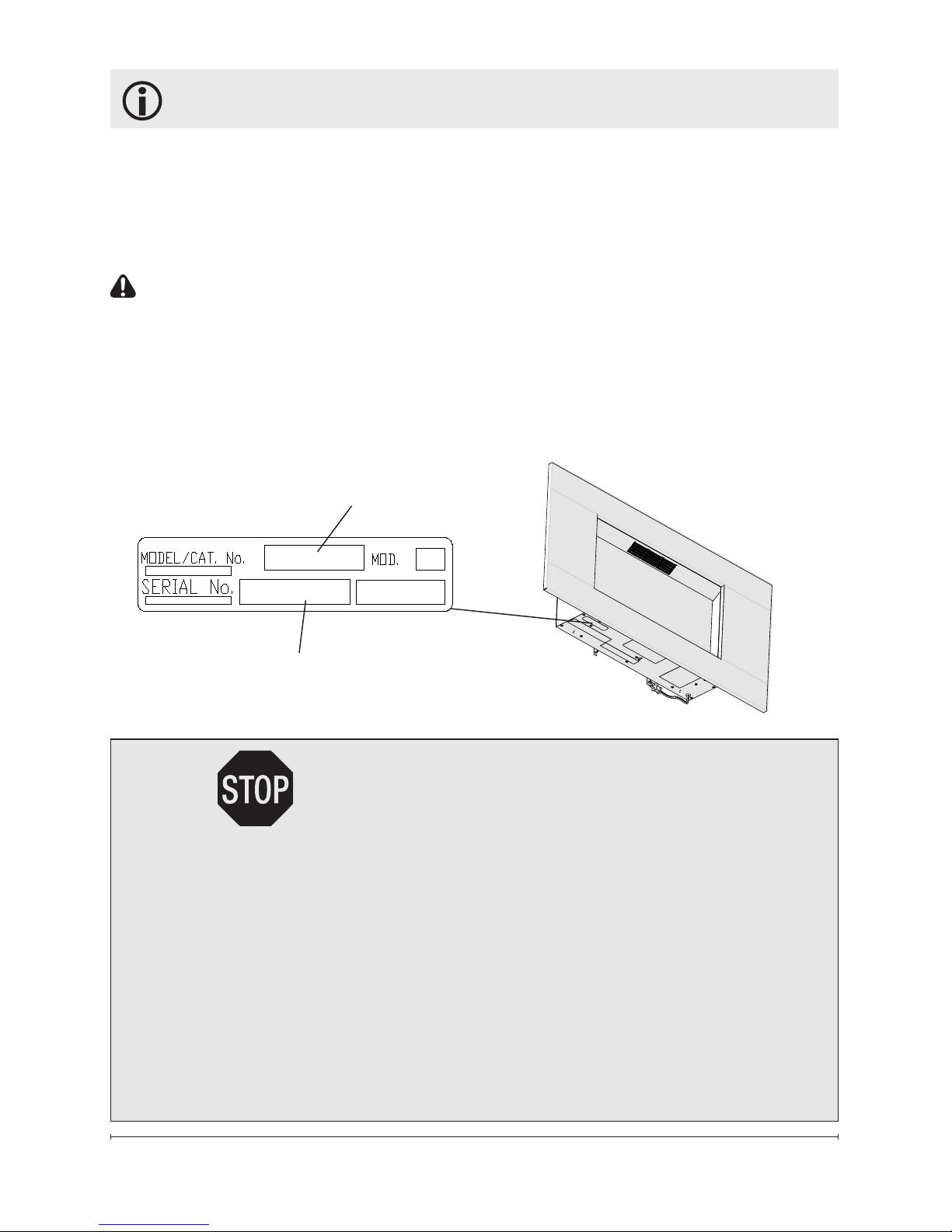
Please record your model and serial numbers below for future
reference: model and serial numbers can be found on the Model and
Serial Number Label of your replace.
NO NEED TO RETURN TO THE STORE
Questions with operation or assembly? Require Parts Information?
Product Under Manufacturer’s Warranty?
Contact us at: www.dimplex.com/customer_support
For Troubleshooting and Technical Support
OR Toll-Free 1-888-DIMPLEX (1-888-346-7539)
Monday to Friday 8:00 a.m. to 4:30 p.m. EST
Please have your model number and product serial
number ready. (See above)
Serial Number Label
Model Number
Page 4

4 www.dimplex.com
When using electrical appliances,
basic precautions should always
be followed to reduce the risk of
fire, electric shock, and injury to
persons, including the following:
① Read all instructions before
using the electric replace.
② This replace is hot when in
use. To avoid burns, do not let
bare skin touch hot surfaces.
The trim around the heater outlet
becomes hot during heater
operation.
③ Extreme caution is necessary
when any heater is used by or
near children or invalids and
whenever the unit is left operating
and unattended.
④ Always unplug the fireplace
when not in use.
⑤ Young children should be
supervised to ensure that they do
not play with the appliance.
⑥ The appliance is not intended
for use by young children
or inrmed persons without
supervision.
⑦ If the supply cord is damaged,
it must be replaced by the
manufacturer, or its service agent,
or a qualied person in order to
avoid a hazard.
IMPORTANT INSTRUCTIONS
⑧ Do not operate any unit with
a damaged cord or plug, or if
the heater has malfunctioned,
or if the electric replace has
been dropped or damaged in
any manner, contact Dimplex
Technical Service at
1-888-346-7539.
⑨Do not use outdoors.
⑩ This fireplace is not intended
for use in bathrooms, laundry
areas and similar indoor locations.
Never locate heater where it may
fall into a bathtub or other water
container.
⑪ High temperature, keep
electrical cords, drapery, and
other furnishings at least 3 feet
(0.9m) from the front of the heater
and away from the side and rear.
⑫ Do not run the cord under
carpeting. Do not cover cord with
throw rugs, runners, or the like.
Arrange cord away from trafc
area and where it will not be
tripped over.
⑬ Do not locate the unit
directly below a xed electrical
convenience outlet.
⑭ To disconnect the replace,
turn the controls off, then remove
the plug from the outlet.
Page 5

5
SAVE THESE INSTRUCTIONS
⑮ Do not insert or allow foreign
objects to enter any ventilation
or exhaust opening as this may
cause an electric shock or re, or
damage to the heater.
⑯ Do not block air intake or
exhaust in any manner. Do not
use on soft surfaces, like a bed,
where openings may become
blocked.
⑰ All electrical heaters have
hot and arcing or sparking parts
inside. Do not use in areas where
gasoline, paint, or ammable
liquids are used or stored or
where the unit will be exposed to
ammable vapors.
⑱ Do not modify the electric
replace. Use it only as described
in this manual. Any other use
not recommended by the
manufacturer may cause re,
electric shock or injury to persons.
⑲ Always plug heaters directly
into a wall outlet/receptacle.
Never use with an extension cord
or relocatable power tap (outlet/
power strip).
⑳ Do not burn wood or other
materials in the electric replace.
㉑
Do not strike the replace
glass.
㉒ Always use a certied
electrician should new circuits or
outlets be required.
㉓ Always use properly grounded,
fused and polarized outlets.
㉔ Disconnect all power supply
before performing any cleaning,
maintenance or relocation of the
unit.
㉕ When transporting or storing
the unit and cord, keep in a
dry place, free from excessive
vibration and store so as to avoid
damage.
CAUTION
RISK OF ELECTRIC SHOCK
DO NOT OPEN
NO USER-SERVICABLE PARTS INSIDE
IMPORTANT INSTRUCTIONS
Page 6
6 www.dimplex.com
!
NOTE: This equipment has been
tested and found to comply with
the limits for Class B digital device,
pursuant to part 15 of the FCC Rules.
These limits are designed to provide
reasonable protection against harmful
interference in a residential installation.
This equipment generates, uses and
can radiate radio frequency energy
and, if not installed and used in
accordance with the instructions, may
cause harmful interference to radio
or television reception, which can be
determined by turning the equipment
off and on, the user is encouraged to
try to correct the interference by one or
more of the following measures:
· Increase the separation between
the equipment and the receiver.
· Connect the equipment into an
outlet on a circuit different from that
to which the receiver is connected.
· Consult the dealer or an
experienced radio/TV technician for
help.
Operation is subject to the following
two conditions: (1) this device may not
cause interference and (2) this device
must accept any interference, including
interference that may cause undesired
operation of the device.
IMPORTANT INSTRUCTIONS
WARNING: Remote control
contains small batteries. Keep away
from children. If swallowed, seek
medical attention immediately.
WARNING: Do not install battery
backwards, charge, put in re or mix
with used or other battery types - may
explode or leak causing injury.
!
NOTE: Changes or modications
not expressly approved by the party
responsible for compliance could
void user's authority to operate the
equipment.
Page 7
7
Quick Reference Guide
1. Before using the fireplace
verify:
• Are the circuit breakers
for the unit on?
2. If you have any technical
questions or concerns
regarding the operation
of your electric fireplace,
or require service contact
customer service.
3. The heater may emit a slight,
harmless odor when first
used. This odor is a normal
condition caused by the initial
heating of internal heater
parts.
Site Selection
!
NOTE: A 15 Amp, 120
Volt circuit is required. A
dedicated circuit is preferred
but not essential in all cases.
A dedicated circuit will be
required if, after installation,
the circuit breaker trips or the
fuse blows on a regular basis
when the heater is operating.
Additional appliances on the
same circuit may exceed the
current rating of the circuit
breaker.
WARNING: Ensure the power
cord is not installed so that
it is pinched or against a
sharp edge and ensure that
Fireplace Installation
the power cord is stored or
secured to avoid tripping or
snagging to reduce the risk of
re, electric shock or injury to
persons.
Construction and electrical
outlet wiring must comply
with local building codes and
other applicable regulations to
reduce the risk of re, electric
shock and injury to persons.
Do not attempt to wire your
own new outlets or circuits. To
reduce the risk of re, electric
shock or injury to persons,
always use a licensed
electrician.
WARNING: The supplied
Page 8
8 www.dimplex.com
Fireplace Installation
hanging components are
designed for use with Dimplex
replaces only. Improper use,
or use for purposes other than
intended, may cause damage
or injury.
Wall Hanging Instructions
WARNING: Failure to install
the replace as instructed
below may result in damage
to the equipment and or may
expose the user to the risk of
re, serious injury, illness or
death.
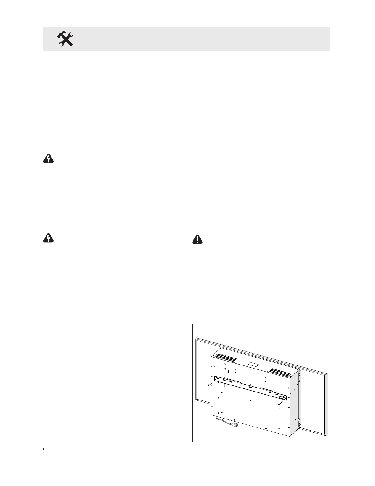
WARNING: The replace
requires the wall hanging
bracket screws to be installed
into a minimum of one wall
studs (Figure 1).
Tools Required
• #2 Phillips screwdriver
• Pencil
• Slot screwdriver
• Bubble level (supplied)
• Drill, and drill bits as required
Approximate time: 30 minutes
for installation
1. Remove the two screws that
secure the hanging bracket
to the back of the rebox.
(Figure 1)
2. Select an appropriate location
Figure 1
to mount the unit on a wall,
above an electrical outlet.
Access to the electrical outlet
must be maintained. Ensure
the installation meets the
national and state/provincial
electrical codes.
!
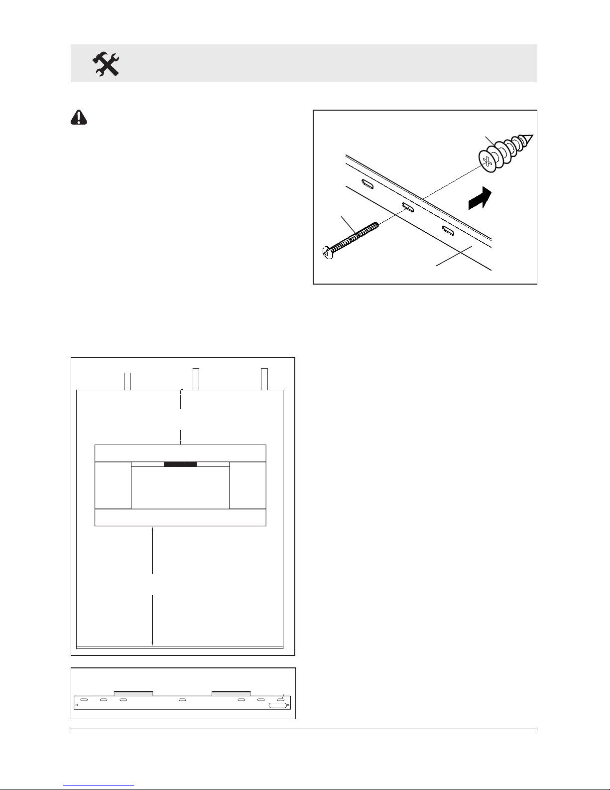
NOTE: It is recommended
that the bottom of the unit
not be mounted higher than
1020mm (40") from the
Fireplace Installation ground
to maintain an optimized
viewing angle of the ame.
(Figure 2)
CAUTION: Ensure that the
top of the unit is at least
152mm (6") from the ceiling
or any object (i.e. Electrical
receptacles) that may
obstruct or be susceptible the
ow or temperature of air out
of the unit.
Page 9
9
A
B
C
D E F
G
40 in (1020 mm)
RECOMMENDED
6 in (152 mm)
MINIMUM
Figure 2
Figure 3
Fireplace Installation
CAUTION: High temperature,
keep electrical cords, drapery,
and other furnishings at least
3 feet (0.9m) from the front of
the heater and away from the
side and rear.
3. The replace must be
mounted at a minimum of
two (2) points, one of which
must be on a wall stud.
Some available hanging
combinations are A-G, B-F,
B-G, C-G, A-F, A-E, A-D and
Wall anchor
Screw
Wall
bracket
Figure 4
D-G. (Figure 3).
!
NOTE: Wall anchors must
be installed in the appropriate
wall locations to fasten the wall
bracket to drywall. (Figure 4)
4. Hold the wall hanging bracket
on the wall and mark the
location of ONE (1) of the
securing holes.
5. Place the bubble level onto
the top of the wall hanging
bracket.
6. Adjust the wall hanging
bracket so the bubble on the
level is centered between the
two black lines.
7. Mark the two (2) screw
locations, on the wall,
ensuring that the wall bracket
stays level.
8. Install the supplied wall
anchors on the drywall
marked locations by placing
Page 10
10 www.dimplex.com
Fireplace Installation
Media Tray
Figure 6
a #2 Phillips screwdriver into
the recess of the anchor.
9. Press the anchor into the wall
in the desired marked position
while turning the anchor
clockwise until it is ush with
the wall.
10. Insert the wall anchor screws
through the wall bracket and
thread into the wall anchors.
Tighten the screw.
11. Install the remaining screw
through the bracket and into
the wall stud.
!
NOTE: At least one of the
screws must be installed into a
wall stud.
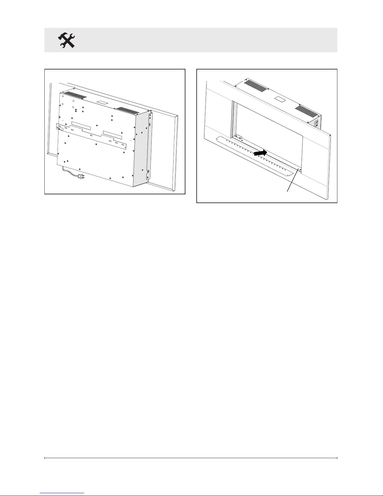
12. Mount the unit on the wall,
so that the tabs on the wall
bracket have been inserted
into the slots on the back of
Figure 5
the rebox. (Figure 5)
13. Excess electrical cord can be
inserted back into the bottom
of the unit, into the cord
storage area.
Media Installation
Depending on the model, the
media may come installed in the
unit, packaged seperately or have
option of being interchanged.
Installed Media
• No additional steps are
required.
Media Seperately Packaged
• SolidMedia: Place media
piece on top of tray. (Figure 6)
• LooseMedia: Carefully pour
and evenly distribute the
media in the Media tray of the
rebox.
Page 11
11
Fireplace Installation
Interchangable Media
• SolidMedia: Comes installed
in the rebox.
• LooseMedia:
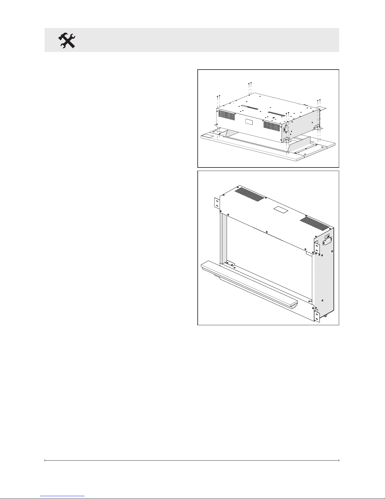
1. Remove rebox from the
wall.
2. Carefully lay the unit down
on a solid at surface with
the front of the unit facing
down. (Figure 7)
!
NOTE: It is recommended
that a protective barrier be used
underneath the unit to ensure
that the front of the frame does
not get scratched.
3. Remove the 4 screws on
each side, that secure the
trim to the rebox.
4. Lift the rebox, directly up,
off of the trim.
!
NOTE: The media is loosly
resting in the media tray and
will easily come out once the
trim has been removed.
5. Reattach the trim to the
rebox.
6. Reattach the rebox to the
wall and carefully pour and
evenly distribute the loose
media in the Media tray of
the rebox.
Figure 7
Figure 8
Page 12
12 www.dimplex.com
Operation
Figure 9
A
B
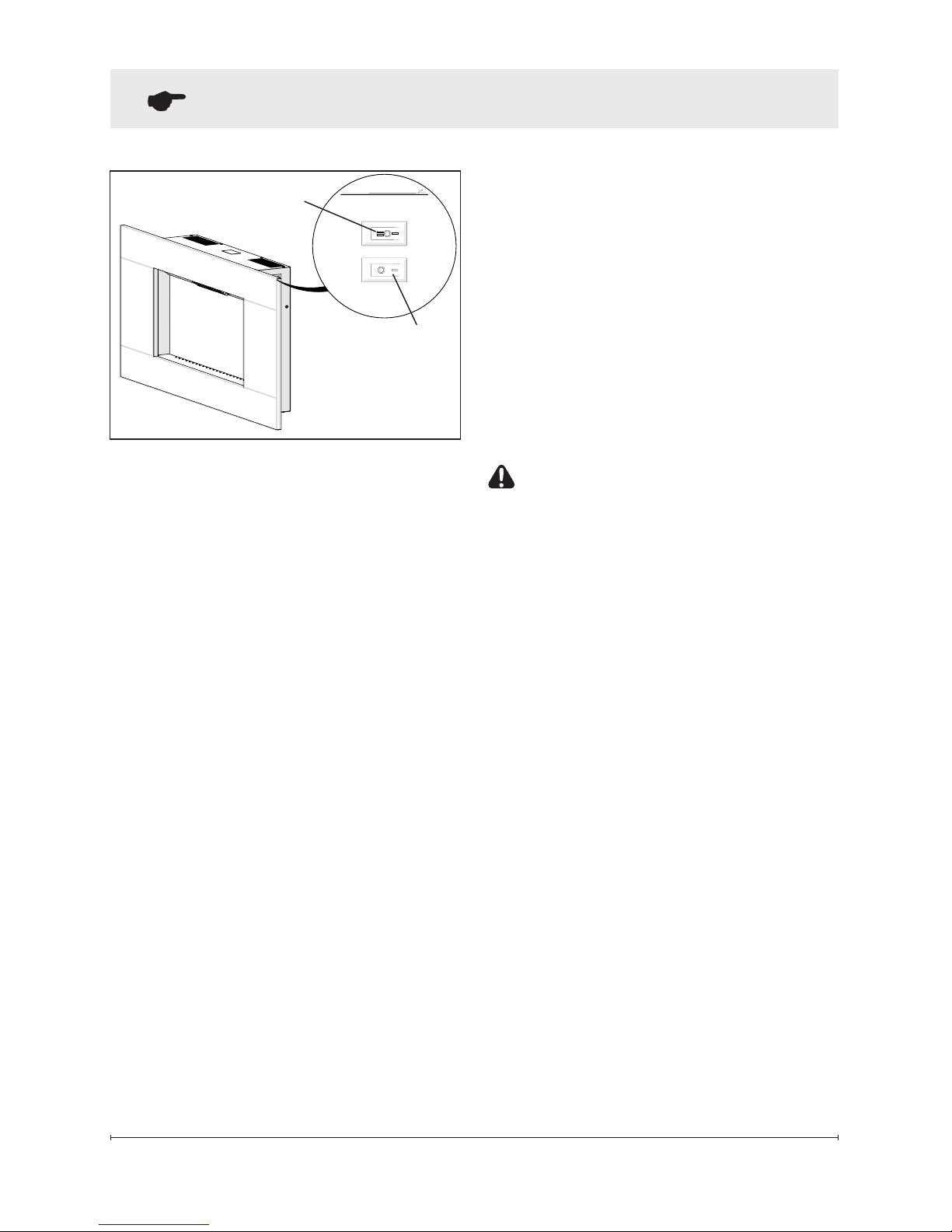
The manual controls for the
electric replace are located on
the right side of the unit (Figure 9).
A. 3-Position Switch
The switch has two (2) On
positions marked with “I” and
“II”. The “I” position is for manual
operation. In this position
the built-in remote control is
bypassed.
The “II” position is for operating
the unit with the provided remote
control. When in “II” position the
unit is operated with the On and
Off buttons of the remote control.
When the switch is in the center
(“O”) position the unit is off.
B. Heat On/Off Switch
The Heat On/Off Switch supplies
power to the heater fan and the
heater element.
Resetting the Temperature
Cutoff Switch
Should the heater overheat, an
automatic cut out will turn the
replace off and it will not come
back on without being reset. It
can be reset by switching the
3-Position Switch to Off and
waiting ve (5) minutes before
switching the unit back on.
CAUTION: If you need to
continuously reset the heater,
disconnect power and call
Dimplex customer service at
1-888-DIMPLEX
(1-888-346-7539).
Remote Control
The replace is supplied with a
radio frequency remote control.
This remote control has a range
of approximately 50 feet (15.25
m), it does not have to be pointed
at the replace and can pass
through most obstacles (including
walls). It is supplied with one
of hundreds of independent
frequencies to prevent
interference with other units.
!
NOTE: Ensure that the
replace’s 3-Position Switch
is set to the remote control
setting (“ II ” position).
Page 13
13
Operation
Figure 10
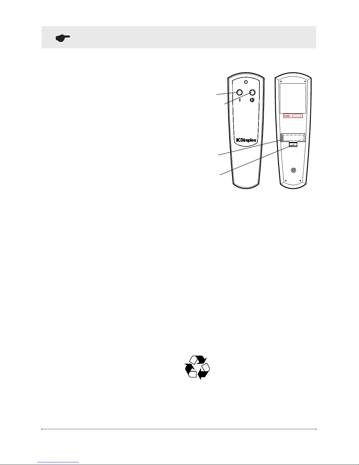
Off Button
On
Button
Battery
Cover
Plastic
Strip
To operate, push the On button
to turn replace on, push the Off
button to turn the replace off.
!
NOTE: Before attempting
any operation with the
remote control, pull the
plastic insulator strip out from
between the remote casing
and battery cover (Figure 10).
Remote Control Initialization/
Reprogramming
In the event that your remote
control ceases to operate your
replace, follow these steps to
re-initialize the remote control and
the remote control receiver in the
replace:
1. Place the 3-Position Switch
(Figure 9A) in the Off (“O”)
position.
2. Wait a minimum of ve (5)
seconds and then place
the 3-Position Switch in the
Remote Control (“II”) position.
3. Within 10 seconds of
changing the switch position,
press the On button located
on the remote control (Figure
10).
This will synchronize the remote
control and the remote control
receiver.
!
NOTE: You will have only 10
seconds to perform this last step.
Failure to do so will result in these
steps needing to be followed
again.
Battery Replacement
To replace the battery:
1. Slide battery cover open on
the remote control (Figure
10).
2. Install one (1) 12-Volt (A23)
battery in the battery holder.
3. Close the battery cover
Battery must be recycled
or disposed of properly.
Check with your Local
Authority or Retailer for recycling
advice in your area.
Page 14

14 www.dimplex.com
Maintenance
WARNING: Disconnect
power before attempting any
maintenance or cleaning to
reduce the risk of re, electric
shock or damage to persons.
Partially Reective Glass
Cleaning
The Partially Reective Glass
is cleaned in the factory during
the assembly operation. During
shipment, installation, handling,
etc., the Partially Reective Glass
may collect dust particles; these
can be removed by dusting lightly
with a clean dry cloth.
To remove ngerprints or other
marks, the Partially Reective
Glass can be cleaned with
a damp cloth. The Partially
Reective Glass should be
completely dried with a lint free
cloth to prevent water spots.
To prevent scratching, do not use
abrasive cleaners.
Fireplace Surface
Cleaning
Use only a damp cloth to clean
painted surfaces of the replace.
Do not use abrasive cleaners.
Servicing
Except for installation and
cleaning described in this
manual, an authorized service
representative should perform
any other servicing.
Page 15

15
Productstowhichthislimitedwarranty
applies
This limited warranty applies to the
following models of your newly purchased
Dimplex electric replace 6908760100
and to newly purchased Dimplex replace
surrounds and trims. This limited warranty
applies only to purchases made in any
province of Canada except for Yukon
Territory, Nunavut, or Northwest Territories
or in any of the 50 States of the USA (and
the District of Columbia) except for Hawaii
and Alaska. This limited warranty applies
to the original purchaser of the product
only and is not transferable.
Productsexcludedfromthislimited
warranty
Products purchased in Yukon Territory,
Nunavut, Northwest Territories, Hawaii,
or Alaska are not covered by this limited
warranty. Products purchased in these
States, provinces, or territories are sold
AS IS without warranty or condition of
any kind (including, without limitation,
any implied warranties or conditions of
merchantability or tness for a particular
purpose) and the entire risk of as to the
quality and performance of the products is
with the purchaser, and in the event of a
defect the purchaser assumes the entire
cost of all necessary servicing or repair.
Whatthislimitedwarrantycoversandfor
howlong
Products, other than replace surrounds
(mantels) and trims, covered by this
limited warranty have been tested and
inspected prior to shipment and, subject
to the provisions of this warranty, Dimplex
warrants such products to be free from
defects in material and workmanship for a
period of 1 year from the date of the rst
purchase of such products.
The limited 1 year warranty period also
applies to any implied warranties that
may exist under applicable law. Some
jurisdictions do not allow limitations on
how long an implied warranty lasts, so
the above limitation may not apply to the
purchaser.
Whatthislimitedwarrantydoesnotcover
This limited warranty does not apply to
products that have been repaired (except
by Dimplex or its authorized service
representatives) or otherwise altered. This
limited warranty does further not apply
to defects resulting from misuse, abuse,
accident, neglect, incorrect installation,
improper maintenance or handling, or
operation with an incorrect power source.
Whatyoumustdotogetserviceunder
thislimitedwarranty
Defects must be brought to the attention of
Dimplex Technical Service by contacting
Dimplex at 1-888-DIMPLEX (1-888346-7539), or 1367 Industrial Road,
Cambridge Ontario, Canada N1R 7G8.
Please have proof of purchase, catalogue/
model and serial numbers available when
calling. Limited warranty service requires a
proof of purchase of the product.
WhatDimplexwilldointheeventofa
defect?
In the event a product or part covered
by this limited warranty is proven to be
defective in material or workmanship
during the 1 year limited warranty period
you have the following rights:
• Dimplex will in its sole discretion
either repair or replace such defective
product or part without charge. If
Dimplex is unable to repair or replace
Warranty
Page 16

16 www.dimplex.com
such product or part, or if repair or
replacement is not commercially
practicable or cannot be timely made,
Dimplex may, in lieu of repair or
replacement, choose to refund the
purchase price for such product or
part.
• Limited warranty service will be
performed solely by dealers or service
agents of Dimplex authorized to
provide limited warranty services.
• Dimplex will not be responsible for,
and the limited warranty services shall
not include, any expense incurred for
installation or removal of the product
or part (or any replacement product or
part) or any labour or transportation
costs. Such costs shall be the
purchaser’s responsibility.
WhatDimplexanditsdealersandservice
agentsarealsonotresponsiblefor:
IN NO EVENT WILL DIMPLEX, OR ITS
DIRECTORS, OFFICERS, OR AGENTS,
BE LIABLE TO the PURCHASER OR
ANY THIRD PARTY, WHETHER IN
CONTRACT, IN TORT, OR ON ANY
OTHER BASIS, FOR ANY INDIRECT,
SPECIAL, PUNITIVE, EXEMPLARY,
CONSEQUENTIAL, OR INCIDENTAL
LOSS, COST, OR DAMAGE ARISING
OUT OF OR IN CONNECTION WITH
THE SALE, MAINTENANCE, USE, OR
INABILITY TO USE THE PRODUCT,
EVEN IF DIMPLEX OR ITS DIRECTORS,
OFFICERS, OR AGENTS HAVE BEEN
ADVISED OF THE POSSIBILITY OF
SUCH LOSSES, COSTS OR DAMAGES,
OR IF SUCH LOSSES, COSTS, OR
DAMAGES ARE FORESEEABLE. IN
NO EVENT WILL DIMPLEX, OR ITS
OFFICERS, DIRECTORS, OR AGENTS
BE LIABLE FOR ANY DIRECT LOSSES,
COSTS, OR DAMAGES THAT EXCEED
THE PURCHASE PRICE OF THE
PRODUCT.
SOME JURISDICTIONS DO NOT ALLOW
THE EXCLUSION OR LIMITATION OF
INCIDENTAL OR CONSEQUENTIAL
DAMAGES, SO THE ABOVE LIMITATION
OR EXCLUSION MAY NOT APPLY TO
THE PURCHASER.
How State and Provincial law apply
This limited warranty gives you specic
legal rights, and you may also have other
rights which vary from jurisdiction to
jurisdiction. The provisions of the United
Nations Convention on Contracts for
the Sale of Goods shall not apply to this
limited warranty or the sale of products
covered by this limited warranty.
Warranty
Page 17

17
Replacement Parts
Heater Assembly (with Cutout) .........................2203610200RP
Partially Reective Glass ..............................5902610100RP
Flame Panel .......................................5902590100RP
Power Cord ........................................4100010800RP
Flicker Motor .......................................2000210500RP
Flicker Rod . . . . . . . . . . . . . . . . . . . . . . . . . . . . . . . . . . . . . . . .5902600100RP
3-Position Switch. . . . . . . . . . . . . . . . . . . . . . . . . . . . . . . . . . . . 2800071100RP
On/Off Switch ......................................2800070700RP
Remote Control Receiver .............................3000380200RP
Remote Control . . . . . . . . . . . . . . . . . . . . . . . . . . . . . . . . . . . . .3000370900RP
LED Light Assembly .................................6908950100RP
LED Driver Board ...................................3001170100RP
Wall Hanging Kit ....................................1025910159RP
Contact Customer Service for specic trim and media replacement part numbers.
© 2013 Dimplex North America Limited
Dimplex North America Limited
1367 Industrial Road
Cambridge ON
Canada N1R 7G8
 Loading...