

Page 1
attention has to be given where children and
vulnerable people are present.
If the mains lead is damaged, it must be replaced
by the manufacturer or its service agent or a
similarly qualied person in order to avoid a
hazard.
Electrical connection
WARNING – THIS APPLIANCE MUST BE EARTHED
The use of an extension lead or multi-plug adaptor is not advised when
connecting this product to the mains. Connection through these devices
could lead to a risk of overloading, overheating and even re at the extension
lead or adaptor due to inadequate connection quality.
This heater must be used on an ~ supply only and the voltage marked on
the heater must correspond to the supply voltage. This heater is tted with
a rewireable plug incorporating a 13 amp fuse. In the event of replacing
the fuse in the plug supplied, a 13 amp fuse approved by ASTA to BS 1362
must be used. If any other type of plug is used, a 15 amp fuse must be
tted in the plug, the adaptor, or at the distribution board.
IMPORTANT : If the plug is not suitable for your socket, the 13 amp plug
should be removed. Before wiring the appropriate plug, please note that
the wires in this mains lead are coloured in accordance with the following
code : GREEN AND YELLOW: EARTH
BLUE : NEUTRAL
BROWN : LIVE
Connect the GREEN AND YELLOW wire to the terminal marked ‘E’ or
by the earth symbol , or coloured GREEN or GREEN AND YELLOW.
Connect the BROWN wire to the terminal marked ‘L’ or coloured RED.
Connect the BLUE wire to the terminal marked ‘N’ or coloured BLACK.
Using the heater
WARNING: DO NOT USE THE HEATER UNTIL THE FEET OR WALL
BRACKETS ARE FITTED CORRECTLY.
The product can be used as an installed or portable unit. Once the desired
application has been decided upon and the requirements below have been
met the product is ready to be used. Simply plug in and switch on at the
wall socket.
Please note – the element has been coated with a protective lm which
will burn off during the rst few minutes of use and may cause a small
amount of fuming. This is quite normal – the fumes are non-toxic and will
quickly disappear.
We recommend that you open a window to ventilate the room when using
the heater for the rst time.
Positioning the heater
Always ensure that the heater is stood on a rm, level base near to,
but not directly beneath, a suitable mains supply socket.
Ensure that curtains and furniture are not positioned close to the
chosen position, as this would create a potential re hazard.
We recommend that the heater should be wall-mounted in rooms
where children may be left unattended, see ‘Important Safety Advice’.
Important Safety Advice
WARNING: This appliance must not be used in
a bathroom.
WARNING: Do not use this heater in the
immediate surroundings of a bath, a shower or
a swimming pool.
WARNING: This heater must not be located
immediately below a xed socket outlet.
The heater carries a warning symbol to
alert the user to the risk of re that exists
if the heater is accidentally covered.
WARNING: In order to avoid a hazard due to
inadvertent resetting of the thermal cut-out,
this appliance must not be supplied through an
external switching device, such as a timer, or
connected to a circuit that is regularly switched
on and off by the utility.
This appliance can be used by children aged
from 8 years and above and persons with
reduced physical, sensory or mental capabilities
or lack of experience or knowledge if they have
been given supervision or instruction concerning
the use of the appliance in a safe way and
understand the hazards involved. Children shall
not play with the appliance. Cleaning and user
maintenance shall not be made by children
without supervision.
Children of less than 3 years should be kept
away unless continuously supervised. Children
aged from 3 years and less than 8 years shall
only switch on/off the appliance provided that
it has been placed or installed in its intended
normal operating position and they have been
given supervision or instruction concerning
the use of the appliance in a safe way and
understand the hazards involved. Children aged
from 3 years and less than 8 years shall not plug
in, regulate and clean the appliance or perform
user maintenance.
CAUTION: Some parts of this product can
become very hot and cause burns. Particular
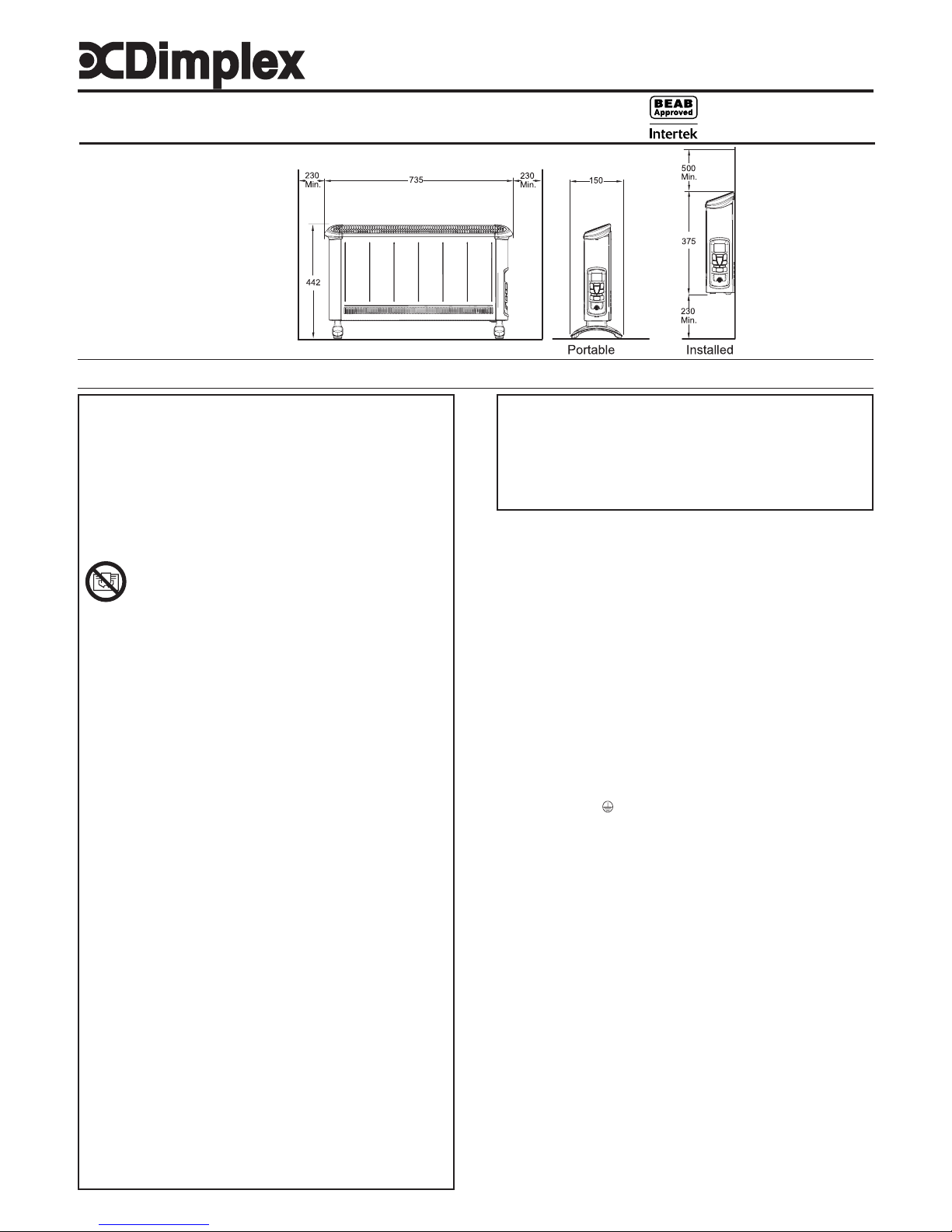
Dimensions
(Millimetres)
Installation and Operating Instructions
Dimplex Convector Heater
Models : 403BTB & 403BT
INDCUK40BT Issue 2
IMPORTANT : THESE INSTRUCTIONS SHOULD BE READ CAREFULLY AND RETAINED FOR FUTURE REFERENCE
As with all portable heating appliances - This product is only suitable for well insulated spaces or occasional use
Fig. 1
Page 2
Portable use
WARNING: THE HEATER SHOULD NEVER BE USED AS A PORTABLE
APPLIANCE WITHOUT THE FEET SECURELY FITTED.
Lay the heater on its back and remove the wall mounting brackets - see
Wall mounting. Locate and remove the foot xing screw - see Fig. 2(a).
Clip the foot in place and secure using the foot xing screw.
NOTE – The wall mounting brackets must be removed before the foot
can be tted.
Wall Mounting (Installed)
Three identical wall mounting brackets are secured to the base of the heater
with a xing screw. To wall mount appliance, rst remove the brackets as
follows, lay the heater on its back and follow the sequence shown - see
Fig. 3. Identify and remove the xing screw securing the brackets located
beside mains cable as shown in (a), pull out brackets and rotate them to
disengage them from the slot and withdraw the brackets from the slot (b).
Select a suitable position, near to a mains power socket whilst ensuring
the minimum mounting clearances are maintained - see Fig. 1. Fix the
two top retaining brackets to the wall, using suitable xings – see Fig. 4.
Locate the heater on the top brackets and allow it to hang in place.
Fit the bottom bracket into the slot in the heater and then x it to the wall.
Test that the heater is now securely xed to the wall.
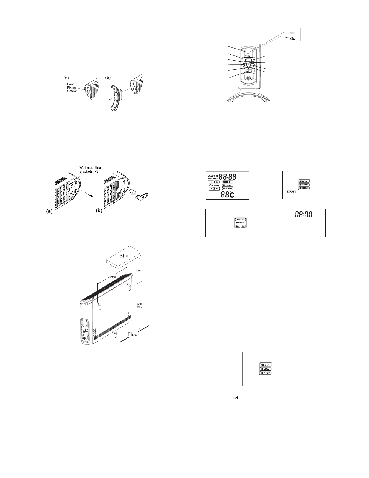
Controls
LCD Display
Heat Neon
Mains Neon
Bluetooth Neon
Standby
Up
Down
Programme
Mode/Pair
Desired
Temperature
Selected
Mode
Selected Heat
Seng
Enter
NOTE: When using the appliance or setting appliance controls always
ensure that the heater is stood on a rm level base. Do not tilt the
appliance at any time.
Operational modes
The electronic control has four control modes: AUTO, MANUAL, BOOST
and STANDBY mode.
Auto Mode
Standby ModeBoost Mode
Manual Mode
In both MANUAL and AUTO mode there are three heat settings options:
‘Intelligent’ Eco Mode - This is the initial default setting, the convector will
automatically start up in this setting once power is applied. The convector
will automatically regulate the room temperature accordingly. In this mode
the convector operates at full power, however the output of the convector is
automatically reduced and regulated as the room temperature approaches
the desired level. This mode optimises energy use by calculating the most
efcient and effective way to achieve the desired temperature setting. The
desired room temperature can be adjusted at any time during operation by
pressing the appropriate key.
Low Heat - In this option, the appliance will operate at a low heat setting,
the appliance will automatically cycle at this setting to maintain the room
temperature setting.
High Heat - In this option, the appliance will operate at a high heat setting,
the appliance will automatically cycle at this setting to maintain the room
temperature setting.
Press the Mode key,‘ ’, to toggle through the modes and the ENTER key
to conrm the mode selection. Note: when selecting the mode if the ENTER
key is not pressed, after 5 seconds the heater will activate the mode shown
on the LCD display.
Fig. 5
Fig. 6
Fig. 7
Fig. 4
Fig. 3
Fig. 2
478
574
Page 3

Initial Operation
When the heater is initially connected to the mains the heater will power
up in MANUAL mode with a set temperature of 30˚C. The Mains and
Heat indication neon will be lit and the LCD display will be as per Fig.8.
For subsequent operations the unit will power up in its previous state, i.e.
if it was in the boost mode when the unit was plugged out when power is
reinstated it will resume in boost mode.
Setting the Time
To set the time press and hold ‘ ’ for two seconds, the time digits will begin
ashing (Fig. 9). Press the ‘ ’ or ‘ ’ buttons to set the time and press
ENTER to conrm. The heater will revert to the previous operational mode.
Flashing
Standby Mode
With the heater ON, if the button is pressed, the heater will go into standby
mode; the heater switches off, the LCD will display the current set time, only
the mains neon remains illuminated. On pressing the button again the
heater will come on in Manual mode and with a set point setting of 25 ˚C.
Manual Operation
Repeatedly press the ‘ ’ button until the manual mode is visible on the
LCD and conrm the mode selection by pressing ENTER. Use the arrow
keys to select the desired heat setting (see Operational modes for heat
setting details) and conrm the selection by pressing the ENTER key. The
desired temperature can be adjusted at any point during the Manual mode
operation, see Setting the Desired temperature.
Auto mode Operation
Repeatedly press the ‘ ’ button until the Auto mode is visible on the LCD
(see Fig.10) and conrm the mode selection by pressing ENTER. The
heater will operate as per the pre-programmed time and temperature prole
(see - Setting the Timer Prole). Note: if no timer prole has been set it
will not be possible to select ‘Auto’ mode, it is necessary to set up a time
program before Auto mode can be selected.
During Auto mode operation the LCD display will show the current heat
status, the active programme segment, the time for the next status change,
the heat setting and the set temperature, see Fig.11 for details.
Time for next status
change (ON at 15:20)
Heat seng
Set temperature
Heat status
Acve segment
Fig. 8
Fig. 9
Fig. 11Fig. 10
Boost mode Operation
Repeatedly press the ‘ ’ button until the Boost mode is visible on the LCD
(see Fig.12) and conrm the mode selection by pressing ENTER. Once
the boost mode is activated it will be necessary select the boost period,
there are three periods available to choose from, 30 minutes, 1 hour and
2 hours. Use the arrow keys to select the desired boost period and conrm
the selection using the ENTER key. The default heat setting is ECO mode
and the set temperature is 25˚C. The set temperature can be adjusted if
desired, see Setting the Desired temperature. When the boost mode is
active the LCD display will show the boost mode, timer period selected
and the desired set temperature. The time display will toggle between the
current time and time remaining for the selected boost period.
Frost protection mode
The appliance has a frost protection mode. This setting is useful in areas
such as garages to assist in the prevention of frost damage. In Manual
mode, if the thermostat is set to its minimum setting ‘5°C’, the heater will
cycle ON and OFF to maintain a temperature of approximately 5°C and
help protect against frosty conditions. The frost protection symbol will
be displayed on the LCD display when frost protection mode is activated.
Indicator Neons
Mains On Neon: The mains neon, (see Fig. 5), remains illuminated when
the power is supplied to the product. Note: This does not indicate whether
the heating elements are on.
Heat Neon: Heat neon remains on when the heating element is active.
Once the desired temperature is reached and the element turns off, the
heat neon will indicate this by remaining off.
Bluetooth Neon: The Bluetooth neon will remain illuminated while
successfully paired to another device.
Setting the Desired Temperature
The desired temperature can be set using the ‘ ’ or ‘ ’ keys. The
temperature can be set from 5˚C to 30˚C and this will be shown on the
display. When the temperature is reached the heater will automatically
switch OFF. If the ambient temperature drops the heater will come on
again automatically.
Setting the Timer Programmes
There are four program segments available, P1, P2, P3 and P4. For each
segment it is possible to set a desired ‘On’ time, ‘Off’ time, Heat mode
and set temperature. It is not necessary to set all four segments if not
required. The default setting is for all segments to be Off. To turn off a preprogrammed segment it is necessary to set both the ‘On’ time and the ‘Off’
time to 00:00. In order to set up a time/temperature prole the following
steps must be completed:
1. To activate the programming screen press the ‘ ’ key. The program
settings screen for P1 will be displayed and the time will be ashing. This
ashing time is the ‘On’ time for P1 and can be adjusted using arrow keys.
Once the desired ‘On’ time has been set press the ENTER key to conrm
the time.
2. Select a heat setting using the arrow keys and conrm the selection
using the ENTER key.
3. Set the desired temperature using the arrow keys and conrm the setting
using the ENTER key.
4. The ‘Off’ time must then be set by using the arrow keys, it is necessary
to then press the ENTER key to conrm the ‘Off’ time setting.
5. The setup screen will then revert to the P1 ‘On’ time set up screen, at
this point it is possible move to the P2 segment by pressing the ‘ ’ key.
6. If required P2, P3 and P4 segment can be set up using steps 1-4 above.
7. If it is not required to set up P2, P3 and P4 segment at this stage, continue
to press the ‘ ’ key until the heater reverts to the previous operational mode.
Alternatively if no keys are pressed the programming mode will time out
and revert to the previous operational mode.
Fig. 12
Page 4

Remote Bluetooth Operation
The appliance can be controlled remotely using a smartphone or similar
device. To facilitate this remote operation it is necessary to rst download
the Dimplex app. The app is available on both android and IOS
devices and is available free from the Apple or Android App store. The
App is compatible with Android version 4.3 and above and IOS version
5 and above.
Once the App has been downloaded it is necessary to pair the appliance
with the smartphone to complete the remote setup. Please follow the steps
shown below:
1. Launch the Dimplex app on the smartphone or similar device.
2. To initiate pairing mode on the appliance press and hold the ‘ ’ button
for two seconds. The LCD screen will go blank with the exception of the
Bluetooth logo ashing in the bottom right hand corner, See Fig.13.This
indicates that the device is advertising to be paired with the app.
3. On the smart phone the appliance should now be visible on the pairing
screen, this will be a unique 6 digit code but will always start with EC, for
example ‘ECBC17’. Select this device and press connect to initiate pairing.
4. Once the paring process is complete the app can be used to control
the appliance.
5. Once paired successfully the Bluetooth logo will stop ashing and the
Bluetooth neon will be illuminated.
Flashing
Safety – overheat protection
For your safety, this appliance is tted with a thermal cut-out. In the event
that the product overheats, the cut-out switches the heater off automatically.
To bring the heater back into operation, remove the cause of the overheating,
then unplug or turn off the electrical supply to the heater for a few minutes.
When the heater has cooled sufciently, re-connect and switch on the
heater.
Fig. 13
The product complies with the European Safety Standards EN60335:2-30 and the European Standard Electromagnetic Compatibility (EMC) EN55014:1,
EN55014:2, EN61000:3-2 and EN61000:3-3 which cover the essential requirements of EMC Directive 2006/95/EC and the LVD Directive 2004/108/EC.
Important Notes
Although this heater is manufactured to comply with the relevant safety
standards, certain types of carpets could become discoloured by the
temperatures under a portable heater. If you are concerned about this,
we recommend that you contact the carpet manufacturer for guidance.
Alternatively, either stand the heater on a suitable base to shield the carpet
or wall-mount it – call our Helpline for further advice.
You may notice some parts of the element appearing to be hotter from time
to time because of the variable airow through the heater. This does not
cause a safety hazard.
The heat outlet grille may become discoloured with use – this is caused by
airborne pollution and is not a fault.
Recycling
For electrical products sold within the European Community.
At the end of the electrical products useful life it should not be
disposed of with household waste.
Please recycle where facilities exist.
Check with your Local Authority or retailer for recycling advice
in your country.
Cleaning
WARNING – ALWAYS DISCONNECT FROM THE POWER SUPPLY
BEFORE CLEANING THE HEATER.
Before commencing cleaning, switch off the heater and allow it to cool.
Disconnect the electricity supply to the appliance.
The outside can be cleaned by wiping it over with a soft damp cloth and
then dried. Do not use abrasive cleaning powders or furniture polish, as
this can damage the surface nish.
To release the heater from the wall bracket for cleaning or redecoration,
depress latch on each bracket and hinge forward.
After Sales Service
Your product is guaranteed for three years from the date of purchase.
After sales information or assistance with this product can be found on
our website www.dimplex.co.uk/support.
Your rights under this guarantee are additional to your statutory rights,
which in turn are not affected by this guarantee.
Please do not return a faulty product to us as this may result in loss or
damage and delay in providing you with a satisfactory service.
If following these steps your product still does not operate you should
return it to your point of purchase.
Please retain your receipt as proof of purchase.
Model Identier(s):
403BTB 403BT
Heat output
Nominal heat output Pnom 3.0 3.0
kW
Minimum heat output (indicative) Pmin 1.0 1.0
kW
Maximum continuous heat output Pmax,c 3.0 3.0
kW
Auxiliary electricity Consumption
At nominal heat output elmax 0.0 0.0
kW
At minimum heat output elmin 0.0 0.0
kW
In standby mode elSB 0.0005 0.0005
kW
Type of heat output/ room temperature control
With mechanical thermostat room temperature control
Yes
Contact details GDHV, Milbrook House, Grange
Drive, Hedge End, Southampton,
SO30 2DF
 Loading...